EP1594229A1 - Verfahren und Vorrichtung zur Ermittlung der Anzahl von abgelaufenen Taktzyklen eines binären Zufallsgenerators - Google Patents
Verfahren und Vorrichtung zur Ermittlung der Anzahl von abgelaufenen Taktzyklen eines binären Zufallsgenerators Download PDFInfo
- Publication number
- EP1594229A1 EP1594229A1 EP05009352A EP05009352A EP1594229A1 EP 1594229 A1 EP1594229 A1 EP 1594229A1 EP 05009352 A EP05009352 A EP 05009352A EP 05009352 A EP05009352 A EP 05009352A EP 1594229 A1 EP1594229 A1 EP 1594229A1
- Authority
- EP
- European Patent Office
- Prior art keywords
- ref
- state vectors
- τil
- clock cycles
- comparison
- Prior art date
- Legal status (The legal status is an assumption and is not a legal conclusion. Google has not performed a legal analysis and makes no representation as to the accuracy of the status listed.)
- Granted
Links
Images



Classifications
-
- G—PHYSICS
- G06—COMPUTING OR CALCULATING; COUNTING
- G06F—ELECTRIC DIGITAL DATA PROCESSING
- G06F7/00—Methods or arrangements for processing data by operating upon the order or content of the data handled
- G06F7/60—Methods or arrangements for performing computations using a digital non-denominational number representation, i.e. number representation without radix; Computing devices using combinations of denominational and non-denominational quantity representations, e.g. using difunction pulse trains, STEELE computers, phase computers
- G06F7/72—Methods or arrangements for performing computations using a digital non-denominational number representation, i.e. number representation without radix; Computing devices using combinations of denominational and non-denominational quantity representations, e.g. using difunction pulse trains, STEELE computers, phase computers using residue arithmetic
- G06F7/724—Finite field arithmetic
-
- G—PHYSICS
- G06—COMPUTING OR CALCULATING; COUNTING
- G06F—ELECTRIC DIGITAL DATA PROCESSING
- G06F7/00—Methods or arrangements for processing data by operating upon the order or content of the data handled
- G06F7/58—Random or pseudo-random number generators
- G06F7/582—Pseudo-random number generators
- G06F7/584—Pseudo-random number generators using finite field arithmetic, e.g. using a linear feedback shift register
Definitions
- the invention relates to a method and a device for determining the number ⁇ of elapsed clock cycles a binary random number generator.
- Such binary random number generators are via shift registers, such.
- shift registers such as shown in DE 41 39 630 Al, realized in which one or more shift register stages are fed back to the input of the shift register to generate a binary random sequence at the output of the shift register.
- the binary random sequence has a periodicity dependent on the configuration of the feedback of the shift register.
- the cycle length n of the binary random sequence is a maximum of 2 m -1 clocks in the case of a shift register with m shift register stages.
- a binary random number generator also for time monitoring in a data transmission system, For example, for the time recording of a fault in a bus station of the data transmission system, used become. Such tasks have been through in series switched counters are detected, their counter readings on Represent the measure of the elapsed time. adversely At such a realization is the high hardware cost with many coupled counter modules, if the covered by the paired counters Time monitoring horizon as in the case of operational monitoring the data transmission path comparatively large is. Also provides simultaneous resetting multiple Counter on overflow of counter combination not one Insignificant source of error because of a bad bit-tilting while resetting a variety of Bit positions is not unlikely.
- a binary random generator can be used for time monitoring be used by changing the states of all shift register stages at the beginning and at the end of the time monitoring for the formation of a state vector respectively and with all possible state vectors of the Feedback shift register stored in a memory are compared.
- identity of the two read state vectors each with one of the stored Comparison state vectors are the ones to stored comparison state vectors correpond Schlen difference a measure of the elapsed time interval determined.
- To this Way is compared to the counter solution hardware minimized Realization to determine a time interval - a feedback shift register - before. Also the probability of erroneous bit-tipping is minimized, as only one bit in each shift register stages is processed.
- the binary random number generator is characterized in its application as a timer by a comparatively high outlay when comparing the read-out state vectors with all the stored comparison state vectors.
- this search process can contain up to 2 m -1 search steps, which is generally not practical in real-time applications.
- the invention is therefore based on the object, a Method and device for time monitoring in Further develop data transmission systems such that the search effort compared to the situation presented above in terms of secure real-time deployment is reduced.
- the invention is achieved by a method for determining the Number ⁇ of elapsed clock cycles of a binary Random generator according to claim 1 and by a Device for determining the number ⁇ of elapsed Clock cycles of a binary random number generator according to claim 10 solved.
- the inventive method and the invention Device for determining the number of expired Clock cycles in a binary random number generator reduces the Search effort by comparing the two read out state vectors and one compared to the maximum possible number of stored comparison state vectors reduced number of stored Comparison state vectors takes place.
- each cycle length n of the binary random sequence of the binary random number generator is utilized. Namely, each cycle length n can be decomposed into a product of a total of j non-divisive integer factors p l .
- time-shifted state vectors each have a periodicity of p l state vectors by the factor n / p l .
- For each of the j prime factors p l of the state vectors by the factor n / p l only a comparison with a total of p l comparison state vectors is necessary therefore to temporal displacement.
- the comparison state vectors a REF '( ⁇ il ) can only be determined if necessary during the time measurement via an iterative calculation.
- all n 'comparison state vectors a REF ' ( ⁇ il) can be calculated in advance.
- These previously calculated comparison state vectors can be stored in a memory and, if necessary, used to carry out the search within the scope of the time measurement.
- To reduce the search process can be binary Search algorithms via decision trees or hash algorithms be used.
- An intermediate form between a preliminary calculation and storage of the comparison state vectors - offline solution - and an on-demand, iterative calculation of the comparison state vectors - online solution - is in the third embodiment of the inventive method for determining the number .DELTA.t of elapsed clock cycles of a binary random number generator in the Precalculation and storage of only a subset of the comparison state vectors. If, in case of need of the time measurement to be carried out, the read state vectors do not coincide with the comparison vectors stored only partially, the read state vectors are cyclically shifted by the number of stored comparison state vectors and the temporally shifted read-out state vectors are compared with the only partially stored comparison state vectors until a time shifted read state vector identical comparison state vector is found.
- This intermediate form is in particular in terms of amount large prime factors p l, to which a plurality of part to be examined comparison state vectors, used to reduce the number of state vectors to be stored comparison.
- the inventive device for determining the number ⁇ of elapsed clock cycles in a binary random number generator in Fig. 1 comprises a binary random number generator 1, a computer unit 2 and a display device 3 for displaying the results.
- the binary random number generator for generating a binary random sequence, which has a periodicity of the cycle length n, is connected via a shift register 4 to a plurality of shift register stages 5 1 , 5 2 , 5 3 ,. 1 realized by means of D flip-flop components. , , and 5 m , in the example shown in Fig. 1, the shift register stages 5 1 , 5 2 , 5 3, 5 4 , 5 5 , 5 6 and 5 7 , realized.
- the binary states at the outputs of all shift register stages 5 1 , 5 2 , .. and 5 m of the shift register 1 are read at the beginning t 1 and at the end t 2 of the time interval .DELTA.t to be measured by a binary input / output module 9 of the computer unit 2 and supplied as state vectors a ( ⁇ 1) and a ( ⁇ 2) to a processing unit (CPU) 10 for further processing in real time, as shown below.
- the arguments ⁇ 1 and ⁇ 2 of the state vectors a ( ⁇ ) represent the duty cycle of the binary random generator 1 at time t 1 (the beginning of the measuring time interval At) and the time t 2 (the end of the measuring time interval At).
- the time t 1 and t 2 read state vectors a ( ⁇ 1) and a ( ⁇ 2) are compared in the context of further processing by the processor unit 10 with comparison state vectors a '( ⁇ i), which are stored in a memory device (RAM) 11.
- the argument ⁇ i represents all clock cycles occurring during a cycle length n of the pseudo-random binary sequence.
- each active edge of the clock (Clk) - in the example shown in FIG. 1 with each positive edge of the clock (Clk) - takes each shift register stage 5 2 , 5 3 to 5 m with the exception of the shift register stage 5 1 at the input 8 of the shift register. 4 at its output the previous binary state at the output of its predecessor shift register stage 5 1 , 5 2 to 5 m-1 .
- the binary state a j ( ⁇ (i + 1)) of the j-th shift register stage 5 j of the shift register 4 at the clock cycle i ( ⁇ + 1) is obtained from the binary state a j-1 ( ⁇ i) according to the upper row of equation (2) ) its predecessor shift register stage - j-1-th shift register stage 5 j-1 - to the clock cycle ⁇ i.
- the shift register stage 5 1 at the input of the shift register 4 takes on the active edge of the clock (Clk) at its output added via the modulo-2 adder 7 previous binary states of the outputs of all feedback shift register stages.
- the binary random sequence s ( ⁇ i) at the individual clock cycles ⁇ i results from binary states a m ( ⁇ i) of the shift register stage 5 m at the output 6 of the shift register 4 to the individual clock cycles ⁇ i.
- s ( ⁇ i) a m ( ⁇ i)
- the state vector a ( ⁇ (i + 1)) of the shift register 4 at one clock cycle, which is exactly one clock cycle later than the clock cycle ⁇ i, can be obtained from Equation (1) using the relationships in Equation (2) via a shift matrix V of FIG State vector a ( ⁇ i) of the shift register 4 to the clock cycle ⁇ i according to equation (5) are determined.
- a ( ⁇ (i + 1)) V * a ( ⁇ i)
- Each cycle length n of the generated binary random sequence can be decomposed according to equation (11) into a product of a total of u-divisive integer factors p 1 , wherein all non-divisive factors p 1 can only assume values greater than one.
- the time-shifted state vector a '( ⁇ i) has a periodicity of p 1 , as further shown below.
- a '( ⁇ i + p 1 ) a '( ⁇ i)
- Equation (13) If the left-hand term of equation (13) is inserted into equation (12) and then the periodicity n of the state vector a ( ⁇ i) taken into account, then the periodicity of the time-shifted state vector a '( ⁇ i) can be calculated comparatively trivially according to equation (14) Cycle length p 1 can be detected.
- the time cycle ⁇ il corresponding to the modulus when dividing the clock cycle ⁇ i by the non-divisive factor p 1 according to equation (15) is the time-shifted state vector a' ( ⁇ ) equal to the clock cycle ⁇ i.
- a '( ⁇ il) a' ( ⁇ i
- p 1 ) a '( ⁇ i)
- the second column vector k 2 of the substitution matrix K can be determined using equation (7) in combination with equation (8) according to equation (19).
- k 2 a ( ⁇ (x + 1)) + k 1 * a 1 ( ⁇ 1)
- the clock cycle ⁇ 1 only the binary states a 1 ( ⁇ 1) and a 2 ( ⁇ 1) of the first and second shift register stage 5 1 and 5 2 have a non-zero value.
- the substitution matrix K is to be built up, which in the next step is to be fed to a matrix multiplication by the factor n / p 1 for the formation of the matrix K n / p 1 .
- An efficient calculation of the matrix K n / p 1 can be achieved by dividing the integer exponent n / p 1 according to equation (21) into a sum of 2 factors:
- the factor c li can assume the value "0" or "1" depending on the existence of the associated two-exponent 2 i .
- the matrix K n / p 1 can be calculated using the results of decomposing the factor n / p 1 according to equation (21) into a sum of matrices K 2 i which are only matrices with two-exponent K 2 i whose associated factor c li has the value "1":
- the matrix K n / p 1 does not have to be computationally determined by multiple matrix multiplication, but can be determined by matrix addition of matrices K 2 i are calculated, which are obtained comparatively simply by repeated squaring of the substitution matrix K.
- the comparison state vectors a REF '( ⁇ (i + 1) 1) are iterated in the context of an online solution for the clock cycle ⁇ (i + 1) l for each non-divisive factor p 1 according to equation (24) a comparison state vector a REF '( ⁇ il) is calculated to the clock cycle ⁇ il and compared directly with the read-out and time-shifted state vector a' ( ⁇ x).
- the advantage of the online solution over the offline solution is that the iterative calculation of the comparison state vectors a REF '( ⁇ il) can be aborted as soon as a read to the read and time-shifted state vector a' ( ⁇ x) matching state comparison vector a REF '( ⁇ il ) is found.
- the computational effort can thus be significantly reduced in the first embodiment compared to the computational effort of the second embodiment.
- the read-out and time-shifted state vector a '( ⁇ x) is to be compared with a multiplicity of comparison state vectors a REF ' ( ⁇ il) - namely a total of p 1 comparison state vectors a REF '( ⁇ il).
- a REF '( ⁇ il) In order to reduce the computational complexity of the comparison state vectors a REF '( ⁇ il), only a subset a REF ''( ⁇ il) of the total p 1 comparison state vectors a REF ' ( ⁇ il) -a, only the comparison state vectors a REF '( ⁇ il) becomes the first o clock cycles of the reduced clock cycle sequence ⁇ il containing a total of p 1 clock cycles - calculated according to equation (25) and stored in a memory (11).
- the read-in and time-shifted state vector is time-shifted in this way and compared with the subset a REF "( ⁇ il) of the comparison state vectors a REF '( ⁇ il) until a comparison state vector matching the read-in and time-shifted state vector a" ( ⁇ x) in the subset a REF "( ⁇ il) of the comparison state vectors a REF '( ⁇ il) is found.
- the comparison state vector a REF '' ( ⁇ xl ') which is appropriate in the subset a REF ''( ⁇ il) of the comparison state vectors a REF ' ( ⁇ i1) for the read in and w-time-shifted state vector a '' ( ⁇ x) supplies the associated clock cycle ⁇ xl ' ,
- the corresponding modulus value ⁇ (u + v) ⁇ x
- modulus values ⁇ (u + v) belonging to the intermediate products p u + v can be determined iteratively, for the iteration steps u + v, u + v-1 and v of equation (30), the sought clock cycle ⁇ x respectively - inverse to the modulus division is represented as the addition of the modulus and the product of divisor and dividend of the modulus division in the triple equation (31):
- the integer factors k, e and f represent the Dividends of the respective Modulus divisions.
- Equation (33) has the two unknowns e and f.
- the unknown factors e and f are respectively determined as a function of the known difference quantity d.
- an equation (34) is constructed which, like the right-hand side of equation (33), also contains a summary decomposition of the non-prime factors p v and p u + v-1 .
- the summary decomposition of the non-prime factors p v and p u + v-1 into equation (34) gives exactly the value "1" to obtain a coefficient comparison between the summation of the non-prime factors p v and p u + v-1 according to Equation (34).
- 35): y * p v - z * p u + v 1 1
- the coefficient comparison shows that the factor e the Product d * y and the factor f corresponds to the product d * z.
- the unknowns e and f can be determined in each case. Since only a single integer unknown pair (y; z) can satisfy equation (34), this can be determined by successive incrementing or decrementing.
- the possible value range of the unknown y lies in the interval -p u + v-1 ⁇ y ⁇ p u + v-1
- the possible value range of the unknown z lies in the interval - p v ⁇ z ⁇ p v
- ⁇ (u + v) ⁇ (u + v-1) + (d - ⁇ * p u ) * z * p u + v 1
- equation (36) If we introduce in equation (36) the modulus value d u of the division of the difference quantity d by the non-divisive factor p u , then equation (36) goes into equation (37): ⁇ (u + v) - ⁇ (u + v-1) + d u * z * p u + v 1
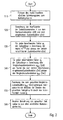
- the binary states in a first method step S10 all the m shift register stages at a time t x, t the beginning of 1 and / or the end t 2 of the to monitoring time interval .DELTA.t, read and a state vector a ( ⁇ x) assigned.
- the measuring clock cycle ⁇ x is the clock cycle associated with the time t x .
- no distinction is made between the beginning t 1 and the end t 2 of the time interval ⁇ t to be monitored in the following, but only the general measuring time t x and the associated measuring cycle ⁇ x are used.
- the coefficients of the substitution matrix K which corresponds to the x-times multiplied displacement matrix V, are calculated.
- the individual column vectors k 1 of the substitution matrix can be calculated according to equations (18), (19) and (20) - equation (18) for the column vector k 1 , equation (19) for the column vector k 2 and equation (20) for the column vectors k 3 to k m - be calculated. This is an iterative calculation, so that for the calculation of the column vector k 1, all column vectors k 1 to k 1-1 arranged in the substitution matrix K to the left of the column vector k 1 must be calculated in previous iteration steps.
- Equation (2) The state vectors a ( ⁇ (i-1)) and a ( ⁇ (x + i-1)) required in particular in equations (19) and (20) for all i from 2 to m can either be used separately for each individual shift register stage Equation (2) can be calculated iteratively from the state vectors a ( ⁇ x) and a (0) or for the entire state vector by means of equations (5) and (6).
- step S30 the respective matrix K n / pl is calculated for each non-divisive factor p 1 of the cycle length n, followed by the state vector a '( ⁇ x), which is shifted in time by the factor n / p 1 for the read-in state vector a ( ⁇ x) Equation (16) is calculated from the starting state vector a (0).
- the matrices K n / p l can be calculated very efficiently by dividing the respective exponents n / p 1 according to equation (21) into a sum of 2 powers by which the matrices K n / p l are calculated according to equation (22 ) are decomposed into a sum of K-matrices with 2-exponents K 2 i , each resulting comparatively simply by multiple squaring of a substitution matrix K.
- the comparison of the read-in, the factor n / p 1 is in each case time-shifted state vector a '( ⁇ x), each with a total of p 1 n by the factor / p 1 time-shifted comparison state vector a REF' ( ⁇ il). Since the determination of the comparison state vectors a REF '( ⁇ il) as well as the type of comparison between the read-in, time-shifted state vector a' ( ⁇ x) and the respectively to be examined comparison state vectors a REF '( ⁇ il) between the individual embodiments is different, is on the description of the matching to the three embodiments method step S40 further down.
- the result of method step S40 in all three embodiments is a time-shifted comparison state vector a REF '( ⁇ xl) suitable for the read-in, time-shifted state vector a' ( ⁇ x) for each non-divisive factor p 1 .
- step S50 the clock cycles ⁇ x1 uniquely associated with the found comparison state vectors a REF '( ⁇ xl) are read from the memory for each of the total non-divisive factors p 1 .
- step S60 all the clock cycles ⁇ xl determined in each case for the overall non-divisive factors p 1 , representing the modulus values of the division of the sought clock cycle ⁇ x by the respective non-divisive factor p 1 , are used for the iterative calculation of the sought clock cycle according to equation (38).
- the intermediates p u + v-1 of the non-divisive factors p 1 required in this case are calculated iteratively from the respective preceding intermediate product p u + v-2 and the respective non-divisive factor p v in accordance with equation (29).
- the unknown factor z can be determined in combination with the also unknown factor y for known non-divisive factor p v and known intermediate product p u + v-1 by iterative incrementing or decrementing to satisfy equation (34).
- the unknown modulus value d u can also be determined by dividing the difference quantity d by the non-divisive factor p u , since the difference quantity d according to equation (33) results from the known clock cycles ⁇ u + v-1 and ⁇ v .
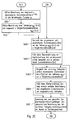
- method step S40 is subdivided into a first sub-method step S40B1, in which the modified displacement matrix V n / p l for each non-divisive factor p 1 on the basis of the displacement matrix V according to equation (6) is calculated.
- step S40B3 the read in, time-shifted state vector a '( ⁇ x) is compared for each non-divisive factor p 1 with the iteratively determined comparison state vector a REF ' ( ⁇ il).
- step S40B4 If, in the next sub-method step S40B4, no identity is found between the read in, time-shifted state vector a '( ⁇ x) and the comparison state vector a REF ''( ⁇ il) iteratively determined for each non-divisive factor p 1 , then a factor p 1 for the respective non-divisive factor is determined associated comparison state vector a REF '( ⁇ (i + 1) l) to the subsequent clock cycle ⁇ (i + 1) l calculated according to equation (24) and the comparison with the read, time-shifted a' ( ⁇ x) supplied in the sub-process step S40B3. Otherwise, the appropriate comparison state vector a REF '( ⁇ xl) is found and the method according to the invention is continued with method step S50, as described above.
- the read-in, time-shifted state vector a '( ⁇ x) determined in process step S30 is compared with each of all comparison state vectors a REF ' ( ⁇ il) from step S05B for identity for each non-divisive factor p 1 . If in this case a suitable comparison state vector a REF '( ⁇ xl) is found, the method is continued with method step S50, as described above.
- the comparison state vectors a REF '( ⁇ il) calculated offline in method step S05B are to be suitably stored in the memory. If a binary search method via a decision tree is used in method step S40B, the read in, time-shifted state vector a '( ⁇ x) is not compared with the comparison state vector a REF ' ( ⁇ il) with respect to all components in a single comparison step, but the individual components become sequential compared to each other.
- the read in, time-shifted state vector a '( ⁇ x) with respect to the still to be compared components only with comparison state vectors a REF ' ( ⁇ il) must be compared in the previously considered components equal binary values to the read, time-shifted state vector a ' ( ⁇ x).
- the resulting reduction of comparison operations requires a storage order of the comparison state vectors a REF '( ⁇ il) in step S05B, in which the comparison state vectors a REF ' ( ⁇ il) are arranged according to their component occupancy in a decision tree hierarchy.
- method step S40 is subdivided into a first sub-method step S40C1, in which the read state vector a ( ⁇ x) which has been shifted in time in method step S30 is used for each large non-divisive factor p 1 with all o comparison state vectors a REF '( ⁇ il) Subset a REF '' ( ⁇ il) is compared to identity.
- the sub-process step S40C2 reads in time-shifted state vector a '( ⁇ x) according to equation (26) by means of the displacement matrix V o * n / p l by a total of o * n / p 1 clock cycles to form the new time-shifted state vector a''( ⁇ x) shifted in time.
- a comparison with the subset a REF "( ⁇ il) of the comparison state vectors a REF '( ⁇ il) is carried out with the state vector a" ( ⁇ x) read in time by o * n / p 1 clock cycles instead of an equivalent comparison of read in, temporally shifted state vector a '( ⁇ x) with the subset a REF ''( ⁇ il) following o comparison state vectors a REF ' ( ⁇ il) performed in terms of identity.
- the invention is not limited to the illustrated three Limited embodiments.
- the Search and compare operations of method steps S40, S40A, S40B3, S40C1 and S40C3 other numeric search and Jump method can be used. Also, the Features of all three embodiments are advantageous be combined.
Landscapes
- Physics & Mathematics (AREA)
- General Physics & Mathematics (AREA)
- Engineering & Computer Science (AREA)
- Computational Mathematics (AREA)
- Mathematical Analysis (AREA)
- Mathematical Optimization (AREA)
- Pure & Applied Mathematics (AREA)
- Theoretical Computer Science (AREA)
- Computing Systems (AREA)
- Mathematical Physics (AREA)
- General Engineering & Computer Science (AREA)
- Complex Calculations (AREA)
Abstract
Description
- Fig. 1
- ein Blockschaltbild einer erfindungsgemäßen Vorrichtung zur Ermittlung der Anzahl von abgelaufenen Taktzyklen eines binären Zufallsgenerators,
- Fig. 2
- ein Flußdiagram eines erfindungsgemäßen Verfahrens zur Ermittlung der Anzahl von abgelaufenen Taktzyklen eines binären Zufallsgenerators,
- Fig. 2A
- ein Teilflußdiagramm des Flußflußdiagramms in Fig. 2 für eine erste Ausführungsform eines erfindungsgemäßen Verfahrens zur Ermittlung der Anzahl von abgelaufenen Taktzyklen eines binären Zufallsgenerators,
- Fig. 2B
- ein Teilflußdiagramm des Flußflußdiagramms in Fig. 2 für eine zweite Ausführungsform eines erfindungsgemäßen Verfahrens zur Ermittlung der Anzahl von abgelaufenen Taktzyklen eines binären Zufallsgenerators und
- Fig. 2C
- ein Teilflußdiagramm des Flußflußdiagramms in Fig. 2 für eine dritte Ausführungsform eines erfindungsgemäßen Verfahrens zur Ermittlung der Anzahl von abgelaufenen Taktzyklen eines binären Zufallsgenerators.










Claims (11)
- Verfahren zur Ermittlung der Anzahl Δτ von zwischen zwei Zeitpunkten t1 und t2 abgelaufenen Taktzyklen eines binären Zufallsgenerators (1), der zur Erzeugung einer binären Zufallsfolge s(τi) mit Zykluslänge n ein Schieberegister (4) mit mindestens einer an seinen Eingang (8) zurückgeführten Schieberegisterstufe (51, 52, .. , 5m) umfaßt, in dem jeweils ein Zustandsvektor a(τ1) und a(τ2) mit den Zuständen aller Schieberegisterstufen (51, 52, .. , 5m) jeweils zum Zeitpunkt t1 und t2 ausgelesen wird,
wobei die Zustandsvektoren a(τ1) und a(τ2) jeweils mit einer gegenüber der maximal möglichen Anzahl n von Vergleichszustandsvektoren aREF(τi) reduzierten Anzahl n' von Vergleichszustandsvektoren aREF'(τi) verglichen werden,
wobei bei Identität zwischen den Zustandsvektoren a(τ1) und a(τ2) und einem der n' Vergleichszustandsvektoren aREF' (τi) der jeweils zugehörige Taktzyklus τ1 und τ2 ermittelt wird und aus der Differenz der Taktzyklen τ1 und τ2 die Anzahl Δτ von abgelaufenen Taktzyklen berechnet wird. - Verfahren zur Ermittlung der Anzahl von abgelaufenen Taktzyklen eines binären Zufallsgenerators nach Anspruch 1,
dadurch gekennzeichnet, daß die n' Vergleichszustandsvektoren aREF'(τi) sämtliche zu allen teilerfremden Faktor pj der Zykluslänge n jeweils gehörigen Vergleichszustandsvektoren aREF' (τil) =aREF (τi *n/p1) umfassen, wobei i jeweils eine ganzzahlige Laufvariable zwischen 0 und pl darstellt. - Verfahren zur Ermittlung der Anzahl von abgelaufenen Taktzyklen eines binären Zufallsgenerators nach Anspruch 2,
dadurch gekennzeichnet, daß die zu den Zeitpunkten t1 und t2 ausgelesenen Zustandsvektoren a(τ1) und a(τ2) über Transformationen für jeden teilerfremden Faktor p1 der Zykluslänge n jeweils zu Zustandsvektoren a(τ1*n/p1) und a (τ2*n/p1) zeitlich verschoben werden, um sie anschließend für jeden teilerfremden Faktor p1 mit allen Vergleichszustandsvektoren aREF' (τil) zu vergleichen und bei Identität zwischen den zeitlich verschobenen Zustandsvektoren a (τ1*n/pl) und a (τ2*n/pl) und einem der Vergleichszustandsvektoren aREF'(τil) die zugehörigen Taktzyklen τ1l und τ2l zu ermitteln, die jeweils dem Moduluswert der Division des Taktzykluses τ1 und τ2 durch den teilerfremden Faktor p1 entsprechen. - Verfahren zur Ermittlung der Anzahl von abgelaufenen Taktzyklen eines binären Zufallsgenerators nach Anspruch 3,
dadurch gekennzeichnet, daß die den Zeitpunkten t1 und t2 entsprechenden Taktzyklen τ1 und τ2 jeweils aus allen zu den jeweiligen teilerfremden Faktoren p1 gehörigen Moduluswerten τ1l und τ2l durch iterative Berechnung ermittelt werden. - Verfahren zur Ermittlung der Anzahl von abgelaufenen Taktzyklen eines binären Zufallsgenerators nach einem der Ansprüche 1 bis 4,
dadurch gekennzeichnet, daß der Zeitpunkt t1 der Initialisierungszeitpunkt des binären Zufallsgenerators (1) ist, der zugehörige Zustandsvektor a(0) ein die Initilisierungswerte der Schieberegisterstufen (51,52,..,5m) beinhaltender Zustandsvektor ist, der zugehörige Taktzyklus τ1 Null ist und die Anzahl Δτ der abgelaufenen Taktzyklen dem Taktzyklus τ2 entspricht. - Verfahren zur Ermittlung der Anzahl von abgelaufenen Taktzyklen eines binären Zufallsgenerators nach einem der Ansprüche 1 bis 5,
dadurch gekennzeichnet, daß die einzelnen zum jeweiligen teilerfremden Faktor p1 gehörigen Vergleichszustandsvektoren aREF' (τi1) mit einem iterativen Berechnungsverfahren sukzessive berechnet und mit den beiden zu den Zeitpunkten t1 und t2 ausgelesenen und für jeden teilerfremden Faktor p1 zeitlich verschobenen Zustandsvektoren a (τ1*n/pl) und a (τ2*n/pl) verglichen werden, bis Identität zwischen dem jeweils iterativ berechneten Vergleichszustandsvektor aREF' (τil) und den Zustandsvektoren a(τ1*n/pl) und a(τ2*n/pl) besteht. - Verfahren zur Ermittlung der Anzahl von abgelaufenen Taktzyklen eines binären Zufallsgenerators nach einem der Ansprüche 1 bis 5,
dadurch gekennzeichnet, daß alle Vergleichszustandsvektoren aREF'(τil) vorab berechnet und abgepeichert werden und anschließend mit den Zustandvektoren a(τ1*n/p1) und a (τ2*n/p1) verglichen werden, bis für jeden teilerfremden Faktor p1 Identität zwischen einem der abgespeicherten Vergleichszustandsvektoren aREF' (τil) und den Zustandsvektoren a (τ1*n/pl) und a (τ2*n/p1) besteht. - Verfahren zur Ermittlung der Anzahl von abgelaufenen Taktzyklen eines binären Zufallsgenerators nach Anspruch 7,
dadurch gekennzeichnet, daß der Vergleich zwischen den abgespeicherten Vergleichszustandsvektoren aREF' (τil) und den Zustandvektoren a (τ1*n/pl) und a (τ2*n/p1) über binäre Suchalgorithmen mittels Entscheidungsbaum oder über Hash-Algorithmen erfolgt. - Verfahren zur Ermittlung der Anzahl von abgelaufenen Taktzyklen eines binären Zufallsgenerators nach Anspruch 7 oder 8,
dadurch gekennzeichnet, daß bei großen teilerfremden Faktoren p1 nur eine Teilmenge aREF'' (τil) der Vergleichszustandsvektoren aREF'(τil) vorab berechnet, abgespeichert und anschließend mit den Zustandsvektoren a(τ1*n/p1) und a (τ2*n/pl) verglichen wird und die Zustandsvektoren a(τ1*n/p1) und a(τ2*n/pl) anschließend solange um eine der Teilmenge aREF'' (τil) der Vergleichsvektoren aREF' (τil) entsprechendende Anzahl o*n/p1 von Schiebeschritten zeitlich verschoben und wiederum mit der Teilmenge aREF'' (τil) der Vergleichszustandsvektoren aREF'(τil) verglichen werden, bis Identität zwischen einem in der Teilmenge aREF'' (τil) abgespeicherten Vergleichszustandsvektoren aREF'(τil) und beiden Zustandsvektoren a(τ1*n/p1) und a (τ2*n/p1) besteht. - Vorrichtung zur Ermittlung der Anzahl Δτ von zwischen zwei Zeitpunkten t1 und t2 abgelaufenen Taktzyklen eines binären Zufallsgenerators (1) mit
einem binären Zufallsgenerator (1), der zur Erzeugung einer binären Zufallsfolge s(τi) mit Zykluslänge n ein Schieberegister (4) mit mindestens einer an seinen Eingang (8) zurückgeführten Schieberegisterstufe (51,52, .. , 5m) umfaßt, und
einer Prozessor-Einheit (10), die über eine Ein-/ Ausgabe-Baugruppe (9) die Binärzustände aller Schieberegisterstufen (51, 52,..,5m) zu den Zeitpunkten t1 und t2 einliest, jeweils zu einem Zustandsvektor a(τ1) und a(τ1) zusammenfaßt und die Zustandsvektoren a (τ1) und a (τ2) jeweils mit einer in einem Speicher (11) abgelegten, gegenüber der maximal möglichen Anzahl n von Vergleichszustandsvektoren aREF(τi) reduzierten Anzahl n' von Vergleichszustandsvektoren aREF'(τil) vergleicht und bei Identität zwischen den Zustandsvektoren a(τ1) und a(τ2) und dem Vergleichszustandsvektor aREF' (τil) den jeweils zugehörigen Taktzyklus τ1 und τ2 zur Ermittlung der Anzahl Δτ von abgelaufenen Taktzyklen zuweist. - Vorrichtung zur Ermittlung der Anzahl Δτ von abgelaufenen Taktzyklen eines binären Zufallsgenerators nach Anspruch 10,
dadurch gekennzeichnet, daß die Vorrichtung zusätzlich eine Anzeige-Einrichtung (3) zur Darstellung der Anzahl Δτ von abgelaufenen Taktzyklen eines binären Zufallsgenerators (1) enthält.
Applications Claiming Priority (2)
| Application Number | Priority Date | Filing Date | Title |
|---|---|---|---|
| DE102004022647.4A DE102004022647B4 (de) | 2004-05-07 | 2004-05-07 | Verfahren und Vorrichtung zur Ermittlung der Anzahl von abgelaufenen Taktzyklen eines binären Zufallsgenerators |
| DE102004022647 | 2004-05-07 |
Publications (2)
| Publication Number | Publication Date |
|---|---|
| EP1594229A1 true EP1594229A1 (de) | 2005-11-09 |
| EP1594229B1 EP1594229B1 (de) | 2009-06-17 |
Family
ID=34935900
Family Applications (1)
| Application Number | Title | Priority Date | Filing Date |
|---|---|---|---|
| EP05009352A Expired - Lifetime EP1594229B1 (de) | 2004-05-07 | 2005-04-28 | Verfahren und Vorrichtung zur Ermittlung der Anzahl von abgelaufenen Taktzyklen eines binären Zufallsgenerators |
Country Status (2)
| Country | Link |
|---|---|
| EP (1) | EP1594229B1 (de) |
| DE (2) | DE102004022647B4 (de) |
Citations (1)
| Publication number | Priority date | Publication date | Assignee | Title |
|---|---|---|---|---|
| DE4139630A1 (de) | 1991-11-30 | 1993-06-03 | Sel Alcatel Ag | Schaltungsanordnung zum erzeugen von binaeren pseudo-zufallsfolgen |
Family Cites Families (1)
| Publication number | Priority date | Publication date | Assignee | Title |
|---|---|---|---|---|
| JP2917962B2 (ja) * | 1997-05-06 | 1999-07-12 | 日本電気株式会社 | M系列を任意にシフトする回路 |
-
2004
- 2004-05-07 DE DE102004022647.4A patent/DE102004022647B4/de not_active Expired - Fee Related
-
2005
- 2005-04-28 EP EP05009352A patent/EP1594229B1/de not_active Expired - Lifetime
- 2005-04-28 DE DE200550007486 patent/DE502005007486D1/de not_active Expired - Fee Related
Patent Citations (1)
| Publication number | Priority date | Publication date | Assignee | Title |
|---|---|---|---|---|
| DE4139630A1 (de) | 1991-11-30 | 1993-06-03 | Sel Alcatel Ag | Schaltungsanordnung zum erzeugen von binaeren pseudo-zufallsfolgen |
Non-Patent Citations (4)
| Title |
|---|
| CLARK D W ET AL: "MAXIMAL AND NEAR-MAXIMAL SHIFT REGISTER SEQUENCES: EFFICIENT EVENT COUNTERS AND EASY DISCRETE LOGARITHMS", IEEE TRANSACTIONS ON COMPUTERS, IEEE INC. NEW YORK, US, vol. 43, no. 5, 1 May 1994 (1994-05-01), pages 560 - 567, XP000442049, ISSN: 0018-9340 * |
| CLARK, D.W. ET AL.: "IEEE Transactions on Computers", vol. 43, 1 May 1994, IEEE INC., article "Maximal and Near-Maximal Shift Register Sequences Efficient Event Counters and Easy Discrete Logarithms", pages: 560 - 567 |
| MUKUND S K ET AL: "On reducing test length in LFSR based testing", FOURTH CSI/IEEE INTERNATIONAL SYMPOSIUM ON VLSI DESIGN, 1991, PROCEEDINGS, NEW DELHI, INDIA 4-8 JAN. 1991, LOS ALAMITOS, CA, USA,IEEE COMPUT. SOC, US, 4 January 1991 (1991-01-04), pages 231 - 236, XP010022331, ISBN: 0-8186-2125-7 * |
| MUKUND, S.K. ET AL.: "On reducing test length in LFSR based testing", FOURTH CSI/IEEE INTERNATIONAL SYMPOSIUM ON VLSI DESIGN, 1991, PROCEEEDINGS, NEW DELHI, INDIA, 4-8 JAN. 1991, LOS ALAMITOS, CA, US, IEEE COMPUT. SOC., 4 January 1991 (1991-01-04), pages 231 - 236, XP010022331, DOI: doi:10.1109/ISVD.1991.185122 |
Also Published As
| Publication number | Publication date |
|---|---|
| EP1594229B1 (de) | 2009-06-17 |
| DE102004022647A1 (de) | 2005-12-22 |
| DE102004022647B4 (de) | 2015-07-09 |
| DE502005007486D1 (de) | 2009-07-30 |
Similar Documents
| Publication | Publication Date | Title |
|---|---|---|
| DE60314584T2 (de) | Maskierung von in einem Restklassensystem zerlegten bzw. faktorisierten Daten | |
| DE69330848T2 (de) | Einrichtung und Verfahren zur digitalen Unterschrift | |
| DE69232431T2 (de) | Vorrichtung zur Lösung von linearen Gleichungssystem | |
| DE3689377T2 (de) | Zufallsfolgengeneratoren. | |
| DE69932740T2 (de) | Verfahren und vorrichtung zur kryptographischen datenverarbeitung | |
| DE68925625T2 (de) | Verfahren zur Rückführung von Fehlern und neuronale Netzstruktur | |
| DE2618823C3 (de) | Generator zur Erzeugung periodischer Folgen | |
| DE1549476B2 (de) | Anordnung zur ausfuehrung von divisionen | |
| DE3854608T2 (de) | Vektorrechnerschaltung, welche schnell eine Berechnung auf drei Eingangsvektoren ausführen kann. | |
| DE2220784A1 (de) | Verfahren und Anordnung zur Echtzeitverarbeitung von elektrischen Signalen | |
| EP1499954B1 (de) | Berechnung eines ergebnisses einer modularen multiplikation | |
| CH627010A5 (de) | ||
| WO2013060466A2 (de) | Bestimmen eines divisionsrests und ermitteln von primzahlkandidaten für eine kryptographische anwendung | |
| DE102008033962A1 (de) | Verfahren und Prozessor-Einrichtung zum Implementieren einer Charakteristik-2-Multiplikation | |
| DE10061315A1 (de) | Verfahren und Vorrichtung zum Erzeugen einer Pseudozufallsfolge | |
| DE102004022647B4 (de) | Verfahren und Vorrichtung zur Ermittlung der Anzahl von abgelaufenen Taktzyklen eines binären Zufallsgenerators | |
| DE10200133B4 (de) | Verfahren und Vorrichtung zur Berechnung von Modulo-Operationen | |
| EP1257904B1 (de) | Verfahren zum erzeugen einer folge von zufallszahlen eines 1/f-rauschens | |
| DE2704641A1 (de) | Digitalfilter | |
| DE3416536C2 (de) | ||
| DE102013224694A1 (de) | Verfahren und Vorrichtung zum Ermitteln eines Gradienten eines datenbasierten Funktionsmodells | |
| DE2554443A1 (de) | Vorrichtung zur bildung von kanaelen unter zuhilfenahme von gleichmaessig auf einer kreislinie verteilten detektoren | |
| DE102006013989A1 (de) | Verfahren zur Reduktion eines Polynoms in einem binären finiten Feld | |
| DE10357751B4 (de) | Vorrichtung und Verfahren zum Bereitstellen einer Testzahl | |
| DE68908202T2 (de) | Binärzahlmultiplizierer mit einer sehr grossen Bitzahl. |
Legal Events
| Date | Code | Title | Description |
|---|---|---|---|
| PUAI | Public reference made under article 153(3) epc to a published international application that has entered the european phase |
Free format text: ORIGINAL CODE: 0009012 |
|
| AK | Designated contracting states |
Kind code of ref document: A1 Designated state(s): AT BE BG CH CY CZ DE DK EE ES FI FR GB GR HU IE IS IT LI LT LU MC NL PL PT RO SE SI SK TR |
|
| AX | Request for extension of the european patent |
Extension state: AL BA HR LV MK YU |
|
| 17P | Request for examination filed |
Effective date: 20051123 |
|
| AKX | Designation fees paid |
Designated state(s): DE FR GB |
|
| 17Q | First examination report despatched |
Effective date: 20060922 |
|
| GRAP | Despatch of communication of intention to grant a patent |
Free format text: ORIGINAL CODE: EPIDOSNIGR1 |
|
| GRAS | Grant fee paid |
Free format text: ORIGINAL CODE: EPIDOSNIGR3 |
|
| GRAA | (expected) grant |
Free format text: ORIGINAL CODE: 0009210 |
|
| AK | Designated contracting states |
Kind code of ref document: B1 Designated state(s): DE FR GB |
|
| REG | Reference to a national code |
Ref country code: GB Ref legal event code: FG4D Free format text: NOT ENGLISH |
|
| REF | Corresponds to: |
Ref document number: 502005007486 Country of ref document: DE Date of ref document: 20090730 Kind code of ref document: P |
|
| PLBE | No opposition filed within time limit |
Free format text: ORIGINAL CODE: 0009261 |
|
| STAA | Information on the status of an ep patent application or granted ep patent |
Free format text: STATUS: NO OPPOSITION FILED WITHIN TIME LIMIT |
|
| 26N | No opposition filed |
Effective date: 20100318 |
|
| GBPC | Gb: european patent ceased through non-payment of renewal fee |
Effective date: 20100428 |
|
| REG | Reference to a national code |
Ref country code: FR Ref legal event code: ST Effective date: 20101230 |
|
| PG25 | Lapsed in a contracting state [announced via postgrant information from national office to epo] |
Ref country code: DE Free format text: LAPSE BECAUSE OF NON-PAYMENT OF DUE FEES Effective date: 20101103 |
|
| PG25 | Lapsed in a contracting state [announced via postgrant information from national office to epo] |
Ref country code: GB Free format text: LAPSE BECAUSE OF NON-PAYMENT OF DUE FEES Effective date: 20100428 |
|
| PG25 | Lapsed in a contracting state [announced via postgrant information from national office to epo] |
Ref country code: FR Free format text: LAPSE BECAUSE OF NON-PAYMENT OF DUE FEES Effective date: 20100430 |