EP1594218B1 - Modulare Anordnung einer verstellbaren Geschwindigkeitssteuerung - Google Patents
Modulare Anordnung einer verstellbaren Geschwindigkeitssteuerung Download PDFInfo
- Publication number
- EP1594218B1 EP1594218B1 EP05103246A EP05103246A EP1594218B1 EP 1594218 B1 EP1594218 B1 EP 1594218B1 EP 05103246 A EP05103246 A EP 05103246A EP 05103246 A EP05103246 A EP 05103246A EP 1594218 B1 EP1594218 B1 EP 1594218B1
- Authority
- EP
- European Patent Office
- Prior art keywords
- module
- option
- connector
- display
- control
- Prior art date
- Legal status (The legal status is an assumption and is not a legal conclusion. Google has not performed a legal analysis and makes no representation as to the accuracy of the status listed.)
- Revoked
Links
- 230000003068 static effect Effects 0.000 claims description 3
- 238000012800 visualization Methods 0.000 claims description 2
- 238000010586 diagram Methods 0.000 description 4
- 238000004891 communication Methods 0.000 description 3
- 239000000654 additive Substances 0.000 description 2
- 230000000996 additive effect Effects 0.000 description 2
- 238000011084 recovery Methods 0.000 description 2
- 230000000903 blocking effect Effects 0.000 description 1
- 238000001816 cooling Methods 0.000 description 1
- 230000013011 mating Effects 0.000 description 1
- 238000000034 method Methods 0.000 description 1
- 238000012986 modification Methods 0.000 description 1
- 230000004048 modification Effects 0.000 description 1
- 238000012545 processing Methods 0.000 description 1
- 230000001105 regulatory effect Effects 0.000 description 1
- 238000010200 validation analysis Methods 0.000 description 1
Images


Classifications
-
- H—ELECTRICITY
- H05—ELECTRIC TECHNIQUES NOT OTHERWISE PROVIDED FOR
- H05K—PRINTED CIRCUITS; CASINGS OR CONSTRUCTIONAL DETAILS OF ELECTRIC APPARATUS; MANUFACTURE OF ASSEMBLAGES OF ELECTRICAL COMPONENTS
- H05K7/00—Constructional details common to different types of electric apparatus
- H05K7/14—Mounting supporting structure in casing or on frame or rack
- H05K7/1422—Printed circuit boards receptacles, e.g. stacked structures, electronic circuit modules or box like frames
- H05K7/1427—Housings
- H05K7/1432—Housings specially adapted for power drive units or power converters
-
- H—ELECTRICITY
- H05—ELECTRIC TECHNIQUES NOT OTHERWISE PROVIDED FOR
- H05K—PRINTED CIRCUITS; CASINGS OR CONSTRUCTIONAL DETAILS OF ELECTRIC APPARATUS; MANUFACTURE OF ASSEMBLAGES OF ELECTRICAL COMPONENTS
- H05K7/00—Constructional details common to different types of electric apparatus
- H05K7/14—Mounting supporting structure in casing or on frame or rack
- H05K7/1422—Printed circuit boards receptacles, e.g. stacked structures, electronic circuit modules or box like frames
- H05K7/1427—Housings
- H05K7/1432—Housings specially adapted for power drive units or power converters
- H05K7/14327—Housings specially adapted for power drive units or power converters having supplementary functional units, e.g. data transfer modules or displays or user interfaces
Definitions
- the present invention relates to an electronic variable speed drive with a modular arrangement comprising, in a box, an inverter delivering polyphase electrical current and provided with static switches controlled by an electronic command and control unit connected to a display module and dialogue used for control, control and visualization arranged on the front panel.
- An electronic variable speed drive as shown schematically in Figure 1 provides an adjustable polyphase current to an asynchronous motor so as to vary its speed. It comprises an inverter with electronic power switches powered, under a filtered DC voltage, by a rectifier. This inverter delivers regulated alternating current on the motor phases.
- the control technique of electronic power switches is known as pulse width modulation (abbreviated MLI and PWM for Pulse Width Modulation), the aim being to generate a voltage as close as possible to a sinusoid.
- MLI and PWM Pulse Width Modulation
- a set of display and dialogue usable by the operator is located on the front panel. It typically has a display or display components, control keys, and at least one communication connector for communicating the drive with other automation devices.
- the object of the present invention is to provide an electronic speed variator having optimum compactness even if the number of optional cards varies.
- the compact cabinet contains the essential components while the optional cards, less common, are stackably mounted on the front panel, behind the front display and dialogue.
- the front face is even thicker as the number of options increases.
- the electronics can recognize the number of options and their positions.
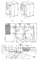
- the electronic variable speed drive according to the invention is characterized in that the box has, on the front face, a control panel provided with a control bus connector connected to the control circuit arranged at the back and adapted to to support either the display module and dialogue connecting via a rear connector to said front connector or at least one option module provided with a through connector which a rear portion can connect to the front connector of the front plate or a an option module and a front portion of which can connect to the rear connector of the display and dialogue module or an adjacent option module so as to constitute a plurality of option modules connected in series and of variable thickness .
- the option module includes electronic means for the internal electronics of the drive to detect option modules added to the front of the control panel.
- the electronic variator according to the invention comprises, in a box or housing 1, a voltage undervoltage OND which receives the output voltage of a rectifier RED associated with a capacitive filter C and powered by L1, L2, L3.
- This voltage inverter is provided with electronic switches T1 to T6 associated with recovery diodes D1 to D6. Each arm of the inverter is equipped with two static power switches each associated with a recovery diode. The midpoints of the pairs of switches are connected to the phase lines U, V, W supplying the electric motor MAS.
- the electronic switches T1 to T6 are controlled by a control and control circuit CC so as to deliver to the motor MAS, on the phase lines U, V, W, a series of pulse modulated in width (pulse modulation or MLI).
- the input terminals making the connection with the phase lines LI, L2, L3 as well as the terminals used for the connection to the motor phases constitute a terminal block which is connected to a power card provided with the various electronic switches and diodes.
- the power board is associated with a cooler and fans for cooling the electronic power switches.
- the drive can be parameterized by a graphical display and dialogue module 2 which is connected to the control and DC control circuit.
- This display-dialogue module is intended to be housed on the front face of the box or box 1 and comprises, at the front, a display 24, scrolling keys in the menus or modification of the values, a key 26 of exit menus and a validation key 27 to enter a menu or validate the new value chosen. It also has a communication connector 29 for connecting the drive to an automation network or to a dialogue or data processing station.
- a control bus connector 21 whose function will be explained below. It comprises at the top of the locking members 22 and at the bottom and rear of the fasteners.
- the front face of the cabinet 1 is occupied by a control panel 3 which is slightly recessed with respect to this front face.
- This front plate carries at the top of the locking tabs 32 and at the bottom of the attachment tabs 33 which can removably fix either a display module and dialogue 2 ( Figures 3 and 4) or an option module 4A ( Figures 5 and 6).
- These hooking tabs 33 cooperate with conjugate hooking means which are provided at the rear of the display-dialogue module 2 or of each option module 4.
- the locking tabs 32 cooperate with conjugated locking members of the display-dialog module 2 or of each option module 4, respectively 22 and 42.
- the said module 4A can carry forwardly the display and dialogue module 2 (FIG 5) or an additional option module 4B (Fig. 6) itself carrying the display-dialogue module 2.
- the apparent or front side of the control panel 3 has a control bus connector 31 which is connected to the control circuit CC.
- an add-on electronic module 6 protected by a removable support 5 and connected by a connector on the front face of the front plate.
- Such an additive module can provide the link with a terminal or PLC.
- a removable cover 28 provided on the display-dialogue module allows access to the add-on electronic module 6 and to the wiring connections.
- Each additive option module 4A, 4B which is housed between the control panel 3 and the display and dialogue module 2 has a rearward connector 41Ar which can mate with the control connector 31 of the front plate or 41Av. an adjacent module and forward a connector 41Av mating with the control connector 41Ar of an adjacent module or 21 of the display-dialogue module 2.
- the circuit shown in FIG. 7 makes it possible to identify by the control bus the number of option modules and their positions.
- the circuit shown in FIG. 7 makes it possible to identify by the control bus the number of option modules and their positions.
- link 7F opens contact 7D.
- a positive pulse on the bus line 7A is detected on line 7C by the microcontroller of the DC circuit.
- the signals 7A and 7B to 0 also have the function of blocking the microcontrollers of the option cards (signal _Reset to 0) and thus to be able to release them one after the other.
- the principle allows with option connectors that are mechanically identical to locate the presence and position of options.
- the option type is then recognized by serial communications between the microcontroller (CC) and the options.
- the bus comprises links and connections that are not shown in FIG. 7.
Landscapes
- Engineering & Computer Science (AREA)
- Microelectronics & Electronic Packaging (AREA)
- Human Computer Interaction (AREA)
- Inverter Devices (AREA)
- Control Of Ac Motors In General (AREA)
- Mounting Of Printed Circuit Boards And The Like (AREA)
- Auxiliary Devices For And Details Of Packaging Control (AREA)
- Control Of Electric Motors In General (AREA)
- Coupling Device And Connection With Printed Circuit (AREA)
- Control Of Throttle Valves Provided In The Intake System Or In The Exhaust System (AREA)
- Sewing Machines And Sewing (AREA)
- Vehicle Body Suspensions (AREA)
Claims (2)
- Elektronischer Drehzahlregler, umfassend, in einem Kasten (1), einen Wechselrichter, der mehrphasigen elektrischen Strom ausgibt und mit statischen Schaltern versehen ist, die von einer elektronischen Steueranlage (CC) gesteuert werden, die mit einem auf der Vorderseite angeordneten Anzeige- und Dialogmodul (2) verbunden ist, das der Überwachung, Steuerung und Sichtanzeige dient, dadurch gekennzeichnet, dass der Kasten (1) vorne eine Steuerungsplatte (3) aufweist, die vorne mit einem Steuerbus-Steckverbinder (31) versehen ist, der hinten mit der elektronischen Steueranlage (CC) verbunden ist und geeignet ist, entweder das Anzeige- und Dialogmodul (2) zu tragen, das durch einen hinteren Steckverbinder mit dem Bus-Steckverbinder (31) verbunden ist, oder mindestens ein Optionsmodul (4A, 4B), das mit einem durchlaufenden Steckverbinder (41) versehen ist, von dem ein Hinterteil (41Ar) mit dem vorderen Steckverbinder (31 oder 41Av) der Platte oder eines Optionsmoduls verbunden werden kann, und von dem ein Vorderteil (41Av) mit dem hinteren Steckverbinder (21 oder 41Ar) des Anzeige- und Dialogmoduls (2) oder eines benachbarten Optionsmoduls (4B) verbunden werden kann, um eine Einheit variabler Dicke zu ergeben, die aus mehreren Optionsmodulen besteht, die in Reihe geschaltet sind und zwischen der Steuerungsplatte und dem Anzeige- und Dialogmodul aufgenommen werden.
- Drehzahlregler nach Anspruch 1, dadurch gekennzeichnet, dass das Optionsmodul (4A, 4B) elektronische Mittel (7D, 7E) aufweist, damit die interne Elektronik des Reglers die Optionsmodule (4A, 4B), die auf der Vorderseite der Steuerungsplatte hinzugefügt werden, erkennt.
Applications Claiming Priority (2)
| Application Number | Priority Date | Filing Date | Title |
|---|---|---|---|
| FR0404723A FR2870084B1 (fr) | 2004-05-04 | 2004-05-04 | Variateur electronique de vitesse a agencement modulaire |
| FR0404723 | 2004-05-04 |
Publications (2)
| Publication Number | Publication Date |
|---|---|
| EP1594218A1 EP1594218A1 (de) | 2005-11-09 |
| EP1594218B1 true EP1594218B1 (de) | 2007-08-29 |
Family
ID=34939436
Family Applications (1)
| Application Number | Title | Priority Date | Filing Date |
|---|---|---|---|
| EP05103246A Revoked EP1594218B1 (de) | 2004-05-04 | 2005-04-21 | Modulare Anordnung einer verstellbaren Geschwindigkeitssteuerung |
Country Status (6)
| Country | Link |
|---|---|
| US (1) | US7599172B2 (de) |
| EP (1) | EP1594218B1 (de) |
| JP (1) | JP4584017B2 (de) |
| AT (1) | ATE371983T1 (de) |
| DE (1) | DE602005002181T2 (de) |
| FR (1) | FR2870084B1 (de) |
Families Citing this family (10)
| Publication number | Priority date | Publication date | Assignee | Title |
|---|---|---|---|---|
| DE202006000125U1 (de) * | 2006-01-05 | 2006-04-27 | Bernic A/S | DIN-Schienen-montierbares Gehäuse für elektrische und/oder elektronische Bauelemente |
| JP4814761B2 (ja) * | 2006-11-15 | 2011-11-16 | 光洋電子工業株式会社 | 小型表示器を備えた表示器装置 |
| JP5313571B2 (ja) * | 2008-07-15 | 2013-10-09 | 東芝シュネデール・インバータ株式会社 | インバータ装置及びそのオプション部品 |
| IT1393288B1 (it) * | 2009-03-12 | 2012-04-20 | Tera S R L | Sistema universale di adattatori modulari per l'installazione rapida di schede elettroniche per l'impiantistica civile e la domotica |
| CN102053664A (zh) * | 2009-11-09 | 2011-05-11 | 鸿富锦精密工业(深圳)有限公司 | 电脑主机及其机箱 |
| USD661254S1 (en) * | 2009-11-20 | 2012-06-05 | Siemens Aktiengesellschaft | Field device |
| SG180051A1 (en) * | 2010-10-28 | 2012-05-30 | Rockwell Automation Asia Pacific Business Ctr Pte Ltd | Display module for toolless coupling with programmable controller |
| CN202453678U (zh) * | 2012-02-13 | 2012-09-26 | 施耐德电器工业公司 | 一种人机界面装置和包含其的控制柜 |
| JP6053636B2 (ja) * | 2013-08-07 | 2016-12-27 | 三菱電機株式会社 | 空気調和機の室外機及び空気調和機の室外機の製造方法 |
| KR101673891B1 (ko) * | 2016-09-05 | 2016-11-08 | 주식회사 엔에스텍 | 철도 차량의 냉난방 설비용 제어 시스템 |
Family Cites Families (39)
| Publication number | Priority date | Publication date | Assignee | Title |
|---|---|---|---|---|
| US3633075A (en) * | 1970-02-18 | 1972-01-04 | Benjamin K Hawkins | Cabinet housing motor controls mounted on plug-in modules |
| JPS5833735A (ja) * | 1981-08-24 | 1983-02-28 | Sony Corp | 電子機器装置 |
| US4401351A (en) * | 1981-09-28 | 1983-08-30 | Advant Corporation | Expandable card cage |
| JPS58193872A (ja) * | 1982-04-30 | 1983-11-11 | 三菱電機株式会社 | 交流エレベ−タの制御装置 |
| JPS6077699A (ja) * | 1983-09-30 | 1985-05-02 | Sharp Corp | パルスモ−タ駆動回路 |
| US4680674A (en) * | 1984-07-16 | 1987-07-14 | Moore Fergus E | Modular computer system with integral electronic bus |
| US4893263A (en) * | 1987-02-12 | 1990-01-09 | Compaq Computer Corporation | Support apparatus for portable computer expansion unit |
| FR2612357B1 (fr) * | 1987-03-12 | 1989-06-09 | Metrologie Pesage Internationa | Module d'affichage et d'introduction de donnees a possibilites de montage multiples |
| JP2545552B2 (ja) * | 1987-09-29 | 1996-10-23 | 株式会社日立製作所 | 高集積制御盤 |
| US4964018A (en) * | 1989-10-05 | 1990-10-16 | Tektronix, Inc. | Multi-purpose display module system for an electronic instrument |
| US5097388A (en) * | 1991-01-31 | 1992-03-17 | Unisys Corporation | Computer system housing monitor with detachable module for providing diverse functionality |
| US5157585A (en) * | 1991-06-27 | 1992-10-20 | Compaq Computer Corporation | Compact AC-powerable portable computer having a CPU and expansion bay in an upper housing pivotally attached to a lower housing |
| US5247285A (en) * | 1992-03-06 | 1993-09-21 | Everex Systems, Inc. | Standup portable personal computer with detachable wireless keyboard and adjustable display |
| US5239712A (en) * | 1992-11-10 | 1993-08-31 | Kinder Gregory V | Shower for individual with hand dysfunction |
| US5430607A (en) * | 1992-12-31 | 1995-07-04 | North Atlantic Industries, Inc. | Rugged modular portable computer including modules hinged along an edge |
| EP0618758B1 (de) * | 1993-04-02 | 1997-01-22 | SAIA-Burgess Electronics AG | Programmierbares Steuergeraet |
| US5345640A (en) * | 1993-07-28 | 1994-09-13 | Goss Mary A | Motorized back scrubber |
| JP3330434B2 (ja) * | 1993-10-14 | 2002-09-30 | 株式会社日立製作所 | インバータ装置 |
| FR2714251B1 (fr) * | 1993-12-22 | 1996-01-12 | Telemecanique | Variateur électronique de vitesse. |
| US5528453A (en) * | 1994-08-05 | 1996-06-18 | Video Express Systems, Inc. | Video recording traveling cart |
| US5636101A (en) * | 1995-09-27 | 1997-06-03 | Dynapro Systems, Inc. | Touch screen enclosure system having touch screen pan and hinged rear enclosure section for ease of serviceability |
| IL116111A0 (en) * | 1995-11-23 | 1997-11-20 | Magnify Electronic Systems 199 | Uninterruptible power system card |
| KR970049283A (ko) * | 1995-12-28 | 1997-07-29 | 김광호 | 기능 확장이 용이한 컴퓨터 |
| EP1014271B1 (de) * | 1997-02-07 | 2006-09-13 | Mitsubishi Denki Kabushiki Kaisha | System und gerät zur bussteuerung |
| JP2000311422A (ja) * | 1999-04-23 | 2000-11-07 | Teac Corp | ディスク装置 |
| US6229584B1 (en) * | 1999-11-15 | 2001-05-08 | Compal Electronics, Inc. | Liquid crystal display monitor having a monitor stand with a replaceable housing part |
| DE10020075C5 (de) * | 2000-04-22 | 2011-06-22 | Pilz GmbH & Co. KG, 73760 | Sicherheitsschaltgeräte-Modulanordnung |
| US6480374B1 (en) * | 2000-11-14 | 2002-11-12 | Inventec Appliances Corp. | Vertically disposed notebook computer |
| US6493230B2 (en) * | 2001-05-01 | 2002-12-10 | Sun Microsystems, Inc. | Modular computer system mechanical interconnection |
| US20030039094A1 (en) * | 2001-08-22 | 2003-02-27 | Sarkinen Scott A. | Closure for equipment case having an integrated display |
| IL146838A0 (en) * | 2001-11-29 | 2002-07-25 | Active Cool Ltd | Active cooling system for cpu |
| US6549424B1 (en) * | 2002-02-28 | 2003-04-15 | Garmin Ltd. | Electronic equipment module mounting apparatus and method |
| US7184272B1 (en) * | 2002-04-05 | 2007-02-27 | Itt Manufacturing Enterprises, Inc. | Modular RF terminal having integrated bus structure |
| US6647564B1 (en) * | 2002-10-18 | 2003-11-18 | Gary Smith | Back scrubber |
| US6795318B2 (en) * | 2002-11-27 | 2004-09-21 | Hewlett-Packard Development Company, Lp. | Portable modular electronic system |
| US6839242B2 (en) * | 2003-02-13 | 2005-01-04 | Rincon Research Corporation | Reconfigurable circuit modules |
| US6996861B1 (en) * | 2003-05-09 | 2006-02-14 | Clark Jr Aaron Thomas | Shower mounted back cleansing and massaging apparatus |
| US7092248B2 (en) * | 2004-01-28 | 2006-08-15 | Paul Shu | Detachable modular computer |
| US7120947B1 (en) * | 2006-02-24 | 2006-10-17 | Octavio Magallanes | Back massaging and cleaning device |
-
2004
- 2004-05-04 FR FR0404723A patent/FR2870084B1/fr not_active Expired - Fee Related
-
2005
- 2005-04-21 EP EP05103246A patent/EP1594218B1/de not_active Revoked
- 2005-04-21 AT AT05103246T patent/ATE371983T1/de not_active IP Right Cessation
- 2005-04-21 DE DE602005002181T patent/DE602005002181T2/de not_active Expired - Lifetime
- 2005-04-26 US US11/114,031 patent/US7599172B2/en not_active Expired - Fee Related
- 2005-05-06 JP JP2005134945A patent/JP4584017B2/ja not_active Expired - Fee Related
Also Published As
| Publication number | Publication date |
|---|---|
| JP4584017B2 (ja) | 2010-11-17 |
| US20050251270A1 (en) | 2005-11-10 |
| FR2870084A1 (fr) | 2005-11-11 |
| ATE371983T1 (de) | 2007-09-15 |
| US7599172B2 (en) | 2009-10-06 |
| DE602005002181D1 (de) | 2007-10-11 |
| EP1594218A1 (de) | 2005-11-09 |
| DE602005002181T2 (de) | 2008-05-21 |
| FR2870084B1 (fr) | 2006-06-16 |
| JP2005323495A (ja) | 2005-11-17 |
Similar Documents
| Publication | Publication Date | Title |
|---|---|---|
| EP1594218A1 (de) | Modulare Anordnung einer verstellbaren Geschwindigkeitssteuerung | |
| FR2834494B1 (fr) | Dispositif de servo-direction electrique | |
| EP0351272A1 (de) | Mit modularem Verbindungsmittel ausgestatteter elektrischer Motor | |
| EP0659040B1 (de) | Zusatzmodul für Drehzahlwandler | |
| FR2491253A1 (fr) | Support pour relais | |
| FR2590414A1 (fr) | Procede et dispositif d'identification electrique de cartes de circuit | |
| EP3443650A1 (de) | Gleichstrom-wechselstrom-leistungsumwandlungsvorrichtung für einen drehzahlvariablen motor und einen hochgeschwindigkeitsmotor | |
| EP3345270B1 (de) | Elektrisches stromverteilungssystem für ein fahrzeug | |
| CA2898070A1 (fr) | Systeme de connexion pour cartes de protection d'un systeme de distribution et rack integrant ledit systeme | |
| EP0232300A1 (de) | Elektronischer hochleistungsspannungssenkungswandler | |
| FR3014285A1 (fr) | Module a circuits relais electrique et centre electrique pour vehicule comprenant un tel module a circuits relais electrique. | |
| EP2091772A1 (de) | Signalisierungsverfahren und vorrichtung für die gestörte funktion eines elektronischen leistungssystem bei einem mehrphasengenerator | |
| FR2848029B1 (fr) | Dispositif de raccordement electrique d'un appareil electrique modulaire a un peigne de raccordement ou analogue | |
| JP4593727B2 (ja) | 分電盤ユニット | |
| FR3091063B1 (fr) | Module électronique de puissance pour moteur électrique intelligent | |
| EP3930166B1 (de) | Wandlermodul | |
| FR2694667A1 (fr) | Dispositif de régulation électronique de vitesse d'un moteur. | |
| CN201167284Y (zh) | 单元变频器 | |
| FR3151663A1 (fr) | Dispositif électronique discriminant pour la détection d’une surtension ou d’une surintensité dans un circuit de commande d’une machine électrique. | |
| EP0145694A2 (de) | Schutzanordnung gegen Störungen und/oder Interferenzen in der Nähe von integrierten Schaltungen | |
| EP2190128A2 (de) | Einrichtung für eine Drahtverbindung zu einer fernen elektrischen Platine. | |
| EP0615132A1 (de) | Elektrisches Testverfahren für Äquipotentialleitungen | |
| EP1950641B1 (de) | Elektrisches Versorgungsmodul für einem Chassis von Elektronikkarten | |
| EP2595296A1 (de) | Steuersystem, das ein Wechselrichtermodul umfasst, das als aktiver Gleichrichter verwendet wird | |
| EP1695564B1 (de) | Modul und verbinder |
Legal Events
| Date | Code | Title | Description |
|---|---|---|---|
| PUAI | Public reference made under article 153(3) epc to a published international application that has entered the european phase |
Free format text: ORIGINAL CODE: 0009012 |
|
| AK | Designated contracting states |
Kind code of ref document: A1 Designated state(s): AT BE BG CH CY CZ DE DK EE ES FI FR GB GR HU IE IS IT LI LT LU MC NL PL PT RO SE SI SK TR |
|
| AX | Request for extension of the european patent |
Extension state: AL BA HR LV MK YU |
|
| 17P | Request for examination filed |
Effective date: 20051124 |
|
| AKX | Designation fees paid |
Designated state(s): AT BE BG CH CY CZ DE DK EE ES FI FR GB GR HU IE IS IT LI LT LU MC NL PL PT RO SE SI SK TR |
|
| GRAP | Despatch of communication of intention to grant a patent |
Free format text: ORIGINAL CODE: EPIDOSNIGR1 |
|
| GRAS | Grant fee paid |
Free format text: ORIGINAL CODE: EPIDOSNIGR3 |
|
| GRAA | (expected) grant |
Free format text: ORIGINAL CODE: 0009210 |
|
| AK | Designated contracting states |
Kind code of ref document: B1 Designated state(s): AT BE BG CH CY CZ DE DK EE ES FI FR GB GR HU IE IS IT LI LT LU MC NL PL PT RO SE SI SK TR |
|
| REG | Reference to a national code |
Ref country code: GB Ref legal event code: FG4D Free format text: NOT ENGLISH |
|
| REG | Reference to a national code |
Ref country code: CH Ref legal event code: EP |
|
| REG | Reference to a national code |
Ref country code: IE Ref legal event code: FG4D Free format text: LANGUAGE OF EP DOCUMENT: FRENCH |
|
| REF | Corresponds to: |
Ref document number: 602005002181 Country of ref document: DE Date of ref document: 20071011 Kind code of ref document: P |
|
| GBT | Gb: translation of ep patent filed (gb section 77(6)(a)/1977) |
Effective date: 20071203 |
|
| PG25 | Lapsed in a contracting state [announced via postgrant information from national office to epo] |
Ref country code: IS Free format text: LAPSE BECAUSE OF FAILURE TO SUBMIT A TRANSLATION OF THE DESCRIPTION OR TO PAY THE FEE WITHIN THE PRESCRIBED TIME-LIMIT Effective date: 20071229 Ref country code: NL Free format text: LAPSE BECAUSE OF FAILURE TO SUBMIT A TRANSLATION OF THE DESCRIPTION OR TO PAY THE FEE WITHIN THE PRESCRIBED TIME-LIMIT Effective date: 20070829 Ref country code: FI Free format text: LAPSE BECAUSE OF FAILURE TO SUBMIT A TRANSLATION OF THE DESCRIPTION OR TO PAY THE FEE WITHIN THE PRESCRIBED TIME-LIMIT Effective date: 20070829 Ref country code: ES Free format text: LAPSE BECAUSE OF FAILURE TO SUBMIT A TRANSLATION OF THE DESCRIPTION OR TO PAY THE FEE WITHIN THE PRESCRIBED TIME-LIMIT Effective date: 20071210 Ref country code: LT Free format text: LAPSE BECAUSE OF FAILURE TO SUBMIT A TRANSLATION OF THE DESCRIPTION OR TO PAY THE FEE WITHIN THE PRESCRIBED TIME-LIMIT Effective date: 20070829 |
|
| NLV1 | Nl: lapsed or annulled due to failure to fulfill the requirements of art. 29p and 29m of the patents act | ||
| PG25 | Lapsed in a contracting state [announced via postgrant information from national office to epo] |
Ref country code: AT Free format text: LAPSE BECAUSE OF FAILURE TO SUBMIT A TRANSLATION OF THE DESCRIPTION OR TO PAY THE FEE WITHIN THE PRESCRIBED TIME-LIMIT Effective date: 20070829 Ref country code: PL Free format text: LAPSE BECAUSE OF FAILURE TO SUBMIT A TRANSLATION OF THE DESCRIPTION OR TO PAY THE FEE WITHIN THE PRESCRIBED TIME-LIMIT Effective date: 20070829 |
|
| REG | Reference to a national code |
Ref country code: IE Ref legal event code: FD4D |
|
| PG25 | Lapsed in a contracting state [announced via postgrant information from national office to epo] |
Ref country code: DK Free format text: LAPSE BECAUSE OF FAILURE TO SUBMIT A TRANSLATION OF THE DESCRIPTION OR TO PAY THE FEE WITHIN THE PRESCRIBED TIME-LIMIT Effective date: 20070829 Ref country code: GR Free format text: LAPSE BECAUSE OF FAILURE TO SUBMIT A TRANSLATION OF THE DESCRIPTION OR TO PAY THE FEE WITHIN THE PRESCRIBED TIME-LIMIT Effective date: 20071130 |
|
| PG25 | Lapsed in a contracting state [announced via postgrant information from national office to epo] |
Ref country code: IE Free format text: LAPSE BECAUSE OF FAILURE TO SUBMIT A TRANSLATION OF THE DESCRIPTION OR TO PAY THE FEE WITHIN THE PRESCRIBED TIME-LIMIT Effective date: 20070829 Ref country code: PT Free format text: LAPSE BECAUSE OF FAILURE TO SUBMIT A TRANSLATION OF THE DESCRIPTION OR TO PAY THE FEE WITHIN THE PRESCRIBED TIME-LIMIT Effective date: 20080129 Ref country code: CZ Free format text: LAPSE BECAUSE OF FAILURE TO SUBMIT A TRANSLATION OF THE DESCRIPTION OR TO PAY THE FEE WITHIN THE PRESCRIBED TIME-LIMIT Effective date: 20070829 Ref country code: SK Free format text: LAPSE BECAUSE OF FAILURE TO SUBMIT A TRANSLATION OF THE DESCRIPTION OR TO PAY THE FEE WITHIN THE PRESCRIBED TIME-LIMIT Effective date: 20070829 |
|
| PLBI | Opposition filed |
Free format text: ORIGINAL CODE: 0009260 |
|
| PLAB | Opposition data, opponent's data or that of the opponent's representative modified |
Free format text: ORIGINAL CODE: 0009299OPPO |
|
| PG25 | Lapsed in a contracting state [announced via postgrant information from national office to epo] |
Ref country code: RO Free format text: LAPSE BECAUSE OF FAILURE TO SUBMIT A TRANSLATION OF THE DESCRIPTION OR TO PAY THE FEE WITHIN THE PRESCRIBED TIME-LIMIT Effective date: 20070829 Ref country code: SE Free format text: LAPSE BECAUSE OF FAILURE TO SUBMIT A TRANSLATION OF THE DESCRIPTION OR TO PAY THE FEE WITHIN THE PRESCRIBED TIME-LIMIT Effective date: 20071129 |
|
| PLAX | Notice of opposition and request to file observation + time limit sent |
Free format text: ORIGINAL CODE: EPIDOSNOBS2 |
|
| 26 | Opposition filed |
Opponent name: SIEMENS AG Effective date: 20080519 |
|
| PLAF | Information modified related to communication of a notice of opposition and request to file observations + time limit |
Free format text: ORIGINAL CODE: EPIDOSCOBS2 |
|
| BERE | Be: lapsed |
Owner name: SCHNEIDER TOSHIBA INVERTER EUROPE SAS Effective date: 20080430 |
|
| PLAF | Information modified related to communication of a notice of opposition and request to file observations + time limit |
Free format text: ORIGINAL CODE: EPIDOSCOBS2 |
|
| PG25 | Lapsed in a contracting state [announced via postgrant information from national office to epo] |
Ref country code: MC Free format text: LAPSE BECAUSE OF NON-PAYMENT OF DUE FEES Effective date: 20080430 |
|
| PLBB | Reply of patent proprietor to notice(s) of opposition received |
Free format text: ORIGINAL CODE: EPIDOSNOBS3 |
|
| PG25 | Lapsed in a contracting state [announced via postgrant information from national office to epo] |
Ref country code: EE Free format text: LAPSE BECAUSE OF FAILURE TO SUBMIT A TRANSLATION OF THE DESCRIPTION OR TO PAY THE FEE WITHIN THE PRESCRIBED TIME-LIMIT Effective date: 20070829 |
|
| PG25 | Lapsed in a contracting state [announced via postgrant information from national office to epo] |
Ref country code: BE Free format text: LAPSE BECAUSE OF NON-PAYMENT OF DUE FEES Effective date: 20080430 |
|
| PG25 | Lapsed in a contracting state [announced via postgrant information from national office to epo] |
Ref country code: SI Free format text: LAPSE BECAUSE OF FAILURE TO SUBMIT A TRANSLATION OF THE DESCRIPTION OR TO PAY THE FEE WITHIN THE PRESCRIBED TIME-LIMIT Effective date: 20070829 |
|
| PG25 | Lapsed in a contracting state [announced via postgrant information from national office to epo] |
Ref country code: CY Free format text: LAPSE BECAUSE OF FAILURE TO SUBMIT A TRANSLATION OF THE DESCRIPTION OR TO PAY THE FEE WITHIN THE PRESCRIBED TIME-LIMIT Effective date: 20070829 |
|
| PG25 | Lapsed in a contracting state [announced via postgrant information from national office to epo] |
Ref country code: BG Free format text: LAPSE BECAUSE OF FAILURE TO SUBMIT A TRANSLATION OF THE DESCRIPTION OR TO PAY THE FEE WITHIN THE PRESCRIBED TIME-LIMIT Effective date: 20071129 |
|
| REG | Reference to a national code |
Ref country code: CH Ref legal event code: PL |
|
| PG25 | Lapsed in a contracting state [announced via postgrant information from national office to epo] |
Ref country code: LI Free format text: LAPSE BECAUSE OF NON-PAYMENT OF DUE FEES Effective date: 20090430 Ref country code: CH Free format text: LAPSE BECAUSE OF NON-PAYMENT OF DUE FEES Effective date: 20090430 |
|
| PG25 | Lapsed in a contracting state [announced via postgrant information from national office to epo] |
Ref country code: LU Free format text: LAPSE BECAUSE OF NON-PAYMENT OF DUE FEES Effective date: 20080421 Ref country code: HU Free format text: LAPSE BECAUSE OF FAILURE TO SUBMIT A TRANSLATION OF THE DESCRIPTION OR TO PAY THE FEE WITHIN THE PRESCRIBED TIME-LIMIT Effective date: 20080301 |
|
| PG25 | Lapsed in a contracting state [announced via postgrant information from national office to epo] |
Ref country code: TR Free format text: LAPSE BECAUSE OF FAILURE TO SUBMIT A TRANSLATION OF THE DESCRIPTION OR TO PAY THE FEE WITHIN THE PRESCRIBED TIME-LIMIT Effective date: 20070829 |
|
| REG | Reference to a national code |
Ref country code: DE Ref legal event code: R064 Ref document number: 602005002181 Country of ref document: DE Ref country code: DE Ref legal event code: R103 Ref document number: 602005002181 Country of ref document: DE |
|
| RDAF | Communication despatched that patent is revoked |
Free format text: ORIGINAL CODE: EPIDOSNREV1 |
|
| PGFP | Annual fee paid to national office [announced via postgrant information from national office to epo] |
Ref country code: DE Payment date: 20150325 Year of fee payment: 11 Ref country code: GB Payment date: 20150414 Year of fee payment: 11 |
|
| RDAG | Patent revoked |
Free format text: ORIGINAL CODE: 0009271 |
|
| STAA | Information on the status of an ep patent application or granted ep patent |
Free format text: STATUS: PATENT REVOKED |
|
| PGFP | Annual fee paid to national office [announced via postgrant information from national office to epo] |
Ref country code: IT Payment date: 20150424 Year of fee payment: 11 Ref country code: FR Payment date: 20150327 Year of fee payment: 11 |
|
| 27W | Patent revoked |
Effective date: 20150304 |
|
| GBPR | Gb: patent revoked under art. 102 of the ep convention designating the uk as contracting state |
Effective date: 20150304 |
|
| REG | Reference to a national code |
Ref country code: DE Ref legal event code: R107 Ref document number: 602005002181 Country of ref document: DE |