EP1594206A1 - Vorrichtung zur Ermittlung von Informationen über den Zustand eines elektrischen Verbrauchers - Google Patents
Vorrichtung zur Ermittlung von Informationen über den Zustand eines elektrischen Verbrauchers Download PDFInfo
- Publication number
- EP1594206A1 EP1594206A1 EP04010844A EP04010844A EP1594206A1 EP 1594206 A1 EP1594206 A1 EP 1594206A1 EP 04010844 A EP04010844 A EP 04010844A EP 04010844 A EP04010844 A EP 04010844A EP 1594206 A1 EP1594206 A1 EP 1594206A1
- Authority
- EP
- European Patent Office
- Prior art keywords
- consumer
- unit
- electronic fuse
- measured values
- memory
- Prior art date
- Legal status (The legal status is an assumption and is not a legal conclusion. Google has not performed a legal analysis and makes no representation as to the accuracy of the status listed.)
- Granted
Links
Images

Classifications
-
- G—PHYSICS
- G05—CONTROLLING; REGULATING
- G05B—CONTROL OR REGULATING SYSTEMS IN GENERAL; FUNCTIONAL ELEMENTS OF SUCH SYSTEMS; MONITORING OR TESTING ARRANGEMENTS FOR SUCH SYSTEMS OR ELEMENTS
- G05B23/00—Testing or monitoring of control systems or parts thereof
- G05B23/02—Electric testing or monitoring
- G05B23/0205—Electric testing or monitoring by means of a monitoring system capable of detecting and responding to faults
- G05B23/0218—Electric testing or monitoring by means of a monitoring system capable of detecting and responding to faults characterised by the fault detection method dealing with either existing or incipient faults
- G05B23/0224—Process history based detection method, e.g. whereby history implies the availability of large amounts of data
- G05B23/0227—Qualitative history assessment, whereby the type of data acted upon, e.g. waveforms, images or patterns, is not relevant, e.g. rule based assessment; if-then decisions
- G05B23/0235—Qualitative history assessment, whereby the type of data acted upon, e.g. waveforms, images or patterns, is not relevant, e.g. rule based assessment; if-then decisions based on a comparison with predetermined threshold or range, e.g. "classical methods", carried out during normal operation; threshold adaptation or choice; when or how to compare with the threshold
-
- G—PHYSICS
- G05—CONTROLLING; REGULATING
- G05B—CONTROL OR REGULATING SYSTEMS IN GENERAL; FUNCTIONAL ELEMENTS OF SUCH SYSTEMS; MONITORING OR TESTING ARRANGEMENTS FOR SUCH SYSTEMS OR ELEMENTS
- G05B23/00—Testing or monitoring of control systems or parts thereof
- G05B23/02—Electric testing or monitoring
- G05B23/0205—Electric testing or monitoring by means of a monitoring system capable of detecting and responding to faults
- G05B23/0259—Electric testing or monitoring by means of a monitoring system capable of detecting and responding to faults characterized by the response to fault detection
- G05B23/0267—Fault communication, e.g. human machine interface [HMI]
- G05B23/027—Alarm generation, e.g. communication protocol; Forms of alarm
-
- H02J13/10—
-
- Y—GENERAL TAGGING OF NEW TECHNOLOGICAL DEVELOPMENTS; GENERAL TAGGING OF CROSS-SECTIONAL TECHNOLOGIES SPANNING OVER SEVERAL SECTIONS OF THE IPC; TECHNICAL SUBJECTS COVERED BY FORMER USPC CROSS-REFERENCE ART COLLECTIONS [XRACs] AND DIGESTS
- Y02—TECHNOLOGIES OR APPLICATIONS FOR MITIGATION OR ADAPTATION AGAINST CLIMATE CHANGE
- Y02B—CLIMATE CHANGE MITIGATION TECHNOLOGIES RELATED TO BUILDINGS, e.g. HOUSING, HOUSE APPLIANCES OR RELATED END-USER APPLICATIONS
- Y02B90/00—Enabling technologies or technologies with a potential or indirect contribution to GHG emissions mitigation
- Y02B90/20—Smart grids as enabling technology in buildings sector
-
- Y—GENERAL TAGGING OF NEW TECHNOLOGICAL DEVELOPMENTS; GENERAL TAGGING OF CROSS-SECTIONAL TECHNOLOGIES SPANNING OVER SEVERAL SECTIONS OF THE IPC; TECHNICAL SUBJECTS COVERED BY FORMER USPC CROSS-REFERENCE ART COLLECTIONS [XRACs] AND DIGESTS
- Y04—INFORMATION OR COMMUNICATION TECHNOLOGIES HAVING AN IMPACT ON OTHER TECHNOLOGY AREAS
- Y04S—SYSTEMS INTEGRATING TECHNOLOGIES RELATED TO POWER NETWORK OPERATION, COMMUNICATION OR INFORMATION TECHNOLOGIES FOR IMPROVING THE ELECTRICAL POWER GENERATION, TRANSMISSION, DISTRIBUTION, MANAGEMENT OR USAGE, i.e. SMART GRIDS
- Y04S10/00—Systems supporting electrical power generation, transmission or distribution
- Y04S10/40—Display of information, e.g. of data or controls
-
- Y—GENERAL TAGGING OF NEW TECHNOLOGICAL DEVELOPMENTS; GENERAL TAGGING OF CROSS-SECTIONAL TECHNOLOGIES SPANNING OVER SEVERAL SECTIONS OF THE IPC; TECHNICAL SUBJECTS COVERED BY FORMER USPC CROSS-REFERENCE ART COLLECTIONS [XRACs] AND DIGESTS
- Y04—INFORMATION OR COMMUNICATION TECHNOLOGIES HAVING AN IMPACT ON OTHER TECHNOLOGY AREAS
- Y04S—SYSTEMS INTEGRATING TECHNOLOGIES RELATED TO POWER NETWORK OPERATION, COMMUNICATION OR INFORMATION TECHNOLOGIES FOR IMPROVING THE ELECTRICAL POWER GENERATION, TRANSMISSION, DISTRIBUTION, MANAGEMENT OR USAGE, i.e. SMART GRIDS
- Y04S10/00—Systems supporting electrical power generation, transmission or distribution
- Y04S10/50—Systems or methods supporting the power network operation or management, involving a certain degree of interaction with the load-side end user applications
- Y04S10/52—Outage or fault management, e.g. fault detection or location
-
- Y—GENERAL TAGGING OF NEW TECHNOLOGICAL DEVELOPMENTS; GENERAL TAGGING OF CROSS-SECTIONAL TECHNOLOGIES SPANNING OVER SEVERAL SECTIONS OF THE IPC; TECHNICAL SUBJECTS COVERED BY FORMER USPC CROSS-REFERENCE ART COLLECTIONS [XRACs] AND DIGESTS
- Y04—INFORMATION OR COMMUNICATION TECHNOLOGIES HAVING AN IMPACT ON OTHER TECHNOLOGY AREAS
- Y04S—SYSTEMS INTEGRATING TECHNOLOGIES RELATED TO POWER NETWORK OPERATION, COMMUNICATION OR INFORMATION TECHNOLOGIES FOR IMPROVING THE ELECTRICAL POWER GENERATION, TRANSMISSION, DISTRIBUTION, MANAGEMENT OR USAGE, i.e. SMART GRIDS
- Y04S20/00—Management or operation of end-user stationary applications or the last stages of power distribution; Controlling, monitoring or operating thereof
Definitions
- the invention relates to a device for determining Information about the state of an electrical consumer.
- the wear on cutting tools For example, turning tools, saws, drills, milling or Punching, by an unclean cut or only by one Breakage of the respective tool. Lying electrical consumers before, which are associated with these tools, then let such failures, for example, using foresee a current-time diagram.
- For pumps and valves shows the wear by an increased power consumption. Fluidic systems require the occurrence of wear an increased pumping capacity.
- the advantages of the invention are in particular that in an electronic fuse already present measured values in a connected to the electronic fuse Forecasting unit as indicator for necessary maintenance work or a necessary replacement of a consumer or with this connected tools, devices or plant parts can be used.
- the forecasting unit which for example is a Personal computer has a database memory on, which has several memory areas. In one of these storage areas References are saved, indicating the need of service measures. Using this References can be aging processes that are slow be monitored. Exceed those of the electronic Fuse derived measurements or derived therefrom Calculated sizes, the references mentioned, then required Measures are initiated.
- One embodiment is to provide the references and the Measured values or the calculated values derived from the measured values in the form of a diagram on a display of the diagnostic unit to visualize. Based on this diagram recognizes the service staff, whether the or the electronic Fuse connected consumers and those with them associated mechanical tools, devices or equipment parts work normally or due to aging or Wear processes are in need of repair or replacement, and, if necessary, initiate the necessary measures.
- Another embodiment is the references and the measured values or the calculated variables derived from the measured values using a stored computer program compare with each other and then when the readings or the calculated values derived therefrom Leave tolerance interval, in alphanumeric and / or graphic form warning messages or maintenance instructions on the display of the forecasting unit.
- the electronic fuse has a measured value memory in which the of a detector unit cached measured values of the electronic fuse become. From this memory you can read the readings at predetermined time intervals or after a call through the diagnostic unit via the communication channel the diagnostic unit to be transmitted.
- the electronic fuse to a self-learning electronic fuse, which is their Reference, which in case of an impermissible deviation of a parameter to be monitored to trigger the shutdown required by the connected consumer, self-determined.
- the consumer belongs a facility that has a wide range of consumers and contains several electronic fuses.
- the electronic fuses over a concentrator connected to the diagnostic unit.
- Such systems For example, in manufacturing technology and the Automation technology used.
- consumers can these are sensors, electronic controls, pumps and Act valves that require a DC supply voltage.
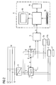
- FIG. 1 shows a sketch of a first exemplary embodiment of a device for determining information about the state of an electrical consumer and of a tool connected thereto.
- an electrical load 2 is connected via an electronic fuse 1 to a power supply 3, which is connected to the AC power W in combination.
- the consumer 2 is connected to a tool 17, for example a saw, a device, for example a processing system, or a system part, for example a robot hand.
- a tool 17 for example a saw
- a device for example a processing system
- a system part for example a robot hand.
- the electronic fuse 1 is a self-learning electronic fuse, which is realized in the form of a single-channel single device. It is arranged in the supply path of the consumer 2 between the power supply 3 and the consumer 2.
- power supply 3 When connected to the AC mains W power supply 3 is a power supply or a rectifier, which provides the required by the load 2 DC supply voltage at its output.
- the alternating current network W has three phase conductors L1, L2, L3 and a neutral conductor N.
- the DC supply voltage provided by the power supply 3 is via a positive + and a ground line - Created to the self-learning electronic fuse 1. From input E of fuse 1 is a supply path P via a detector unit 8 to a supply output A of the fuse 1. By means of the at this supply output present DC supply voltage is the consumer 2 supplied.
- the self-learning electronic fuse is 1 via its interface S and a communication channel K with a forecasting unit 4 connected.
- this forecasting unit 4 is a personal computer, the one Keyboard 4a, a display 4b, a database memory 4c and a computing and control unit 4d has.
- Via the communication channel K are determined by means of the detector unit 8 Transfer measured values to the forecasting unit 4.
- These derives data from the mentioned measured values, the information about the state of the connected to the fuse 1 electrical load 2 and connected to this Give tool.
- the database memory 4c stores references that the Necessity of service measures. With these references For example, it is a minimum value and a maximum value for a parameter to be monitored.
- the arithmetic unit 4d checks whether the communication channel supplied measured values of the parameter to be monitored between the minimum value and the maximum value. So long this is the case, the consumer works 2 and that to this connected tool properly and is in good condition. On the other hand, the delivered measured values leave the tolerance range defined by the minimum value and the maximum value, then the arithmetic unit 4d recognizes that the Consumer 2 or the tool 17 due to aging and / or wear is in need of repair or replacement and signals this to the service personnel through an alphanumeric or graphic display on the display 4b. The service staff Manages the required response in response to this ad Measures.
- the tolerance range mentioned by the minimum value and The maximum value is defined based on object dependencies between the shutdown of the electrical load and the wear of the tool connected to it. is this wear has progressed to a certain degree then this shows up in the of the detector unit. 8 supplied measured values.
- the arithmetic unit 4d recognizes the Progress of wear and thus the upcoming Failure of the tool, allowing timely appropriate countermeasures can be taken.
- the storage of the minimum value and the maximum value for the parameter to be monitored in the database memory 4 c takes place by means of the keyboard 4 a of the forecasting unit 4.
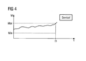
- the display 4b is a display of a diagram, in which the temporal course of the delivered measured values as well the predetermined minimum value and the predetermined maximum value are illustrated.
- An example of such Display is shown in FIG. There are on the Abscissa the time t and plotted on the ordinate the measured values M. From the time course of the measured values given curve, it can be seen that the measured values up to Time t1 within the min by a minimum value and a maximum value Max defined tolerance interval are and leave this tolerance interval at time t1.
- the electronic fuse 1 to the forecasting unit 4 transmitted measured values in another Memory area of database memory 4c archived.
- the system - could be the cause of the inadequate Work results are that several of these Consumers in the immediate vicinity of the edge of each Tolerance range work and thereby a summation of smaller Work inaccuracies occurs in their entirety lead to an unacceptable work result.
- This can be recognized by the archived measured values.
- Countermeasure is a reduction in such a case the tolerance ranges, so that in future a previous maintenance or earlier replacement of consumers or with tools, devices or tools connected to them Plant parts are done.
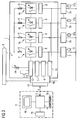
- FIG. 2 shows a sketch of a second exemplary embodiment of a device for determining information about the state of an electrical consumer and of a tool connected thereto.
- two realized as a single-channel devices self-learning electronic fuses 1 and 1a are provided.
- the fuse 1 is arranged in the supply path of a consumer 2 between a power supply 3 and the consumer 2.
- the fuse 1a is located in the supply path of a load 2a between the power supply 3 and the load 2a.
- the consumer 2 is connected to a tool 17 and the consumer 2a to a tool 17a.
- the power supply 3 is connected to the AC mains W. This has three phase conductors L1, L2, L3 and a neutral conductor N, which are each connected to an input of the power supply 3.
- the power supply 3 is a power supply or a rectifier unit, which provides at its output required by the consumers 2 and 2a DC supply voltage. This is transmitted in each case via a positive line + and a ground line - to the self-learning fuses 1 and 1a and from these to the consumers 2 and 2a.
- the self-learning electronic fuses 1 and 1a are further connected to a concentrator 5, respectively. This is intended to collect the measurement signals determined by a detector unit 8 of the respective fuse and then to transmit them via a communication channel K to a prognostic unit 4. Furthermore, a communication channel K is also provided between the fuses 1 and 1a. About this data present in the fuse 1 data can be transferred to the fuse 1a and vice versa.
- the fuse 1 is intended to be in case of inadmissible Deviation of one in the supply path to the consumer 2 to trigger the parameter to be monitored, d. H. the supply path to interrupt the consumer 2.
- the fuse 1a serves in case of an impermissible deviation of an im Supply path to the consumer 2a to be monitored parameters to trigger, d. H. the supply path to the consumer 2a to interrupt.
- the forecasting unit 4 is a personal computer, a keyboard 4a, a display 4b, a database memory 4c and a computing and control unit 4d.
- the prognosis unit 4 derives from the her over the Communication channel K transmitted data from the data Information about the state of the fuses 1 and 1a connected electrical loads 2 and 2a and the give connected tools. For this purpose are in a memory area of the database memory 4c references saved, which concern the necessity of service measures. These references are, for example by a minimum value and a maximum value for one to be monitored Parameter.
- the arithmetic unit 4d checks whether the Measurements delivered via the communication channel monitoring parameter between the minimum value and the maximum value lie. As long as this is the case, the work Consumer 2 or 2a and the tools connected to it properly and are in good condition.
- the arithmetic unit 4d recognizes that the consumer 2 or 2a or the respective associated tool due to aging and / or wear in need of repair or replacement is and signals this to the service personnel by an alphanumeric or graphic display on the display 4b.
- the Service personnel direct the required response to this ad Measures.
- the tolerance range mentioned by the minimum value and The maximum value is defined based on object dependencies between the shutdown of the electrical load and the wear of the tool. Is this wear up progressed to a certain degree, then shows up this in the measured values supplied by the detector unit 8.
- the arithmetic unit 4d detects the progress of wear and thus the imminent failure of the tool so that suitable countermeasures can be taken in good time.
- the storage of the minimum value and the maximum value for the parameter to be monitored in the database memory 4d takes place by means of the keyboard 4a of the forecasting unit 4.
- the display 4b is a display of diagrams in which the time course of the respective consumer corresponding measured values and the specified minimum value and the predetermined maximum value are illustrated, as is has already been explained above with reference to FIG.
- those from the concentrator 5 through the communication channel K transmitted to the forecasting unit 4 measured values in another memory area of the database memory 4c archived. This creates the opportunity to become one later use these readings as needed to be able to.
- FIG. 3 shows a sketch of a third exemplary embodiment for a device for obtaining information about the state of an electrical consumer and a with this connected tool.
- a multi-channel self-learning electronic Fuse 1 provided in the supply paths of electrical loads 2, 2a, 2b, ..., 2n between a Power supply 3 and the aforementioned consumers arranged is.
- the consumers are each equipped with a tool 17, 17a, 17b, ..., 17n connected.
- the power supply 3 is itself to a power supply or a rectifier unit, the their output required by the consumers DC supply voltage provides. This is about a Plus line + and a ground line - to the self-learning electronic fuse 1 and from this to the consumer 2, ..., 2n passed.
- the supply paths P, ..., Pn provided.
- the supply path P is connected to the consumer 2, the supply path Pa to the consumer 2a, the supply path Pb to the consumer 2b and the supply path Pn to the consumer 2n.
- the self-learning electronic fuse 1 is still via a communication channel K with a forecasting unit 4 connected.
- a forecasting unit 4 is a personal computer, a keyboard 4a, a display 4b, a database memory 4c and a computing and control unit 4d.
- the forecasting unit 4 derives from it via the communication channel K derived data from the data about the state of the connected to the fuse 1 electrical loads 2, 2a, 2b, ..., 2n and the respective Give tools.
- the fuse 1 has an input E, at which the of the Power supply 3 supplied positive DC supply voltage is applied. At this input E is a parallel connection the supply paths P, Pa, Pb, ..., Pn connected. Everyone this supply path has a series connection, the serving as a line protection fuse 6, a electronic switch 7 and a detector unit 8 contains.
- the output of the detector unit 8 is associated with one respectively Consumer 2, 2a, 2b, ..., 2n connected. Farther are the outputs of the detector units 8 to a multiplexer 10 created. Its output is connected to a circuit block 9 connected, which has an analog-to-digital converter and an n-fold memory having. The n-fold memory is for caching provided the measured values by means of the detector units 8 are recorded.
- the electronic fuse 1 shown in FIG. 3 is further provided with a button 13, by means of which the Self-learning process can be activated manually. Furthermore, the in the figure 3 electronic fuse 1 with a to the control logic 12 connected adjustable resistor provided by means of which the tripping characteristic of electronic switch 1 is adjustable.
- the evaluation electronics 16 shown in FIG the circuit blocks 9 - 12 belong is preferably in Form of a microcomputer realized in the housing of the electronic fuse 1 is installed.
- the evaluation electronics 16 is connected via an interface 15 to the communication channel K in connection. Via this communication channel K are in normal operation of the system by the detector units 8 measured values, which are stored in the n-fold measured value memory in Circuit block 9 are cached to the forecasting unit 4 transmitted.
- the ground signal delivered by the power supply - is with connected to the ground terminals of the consumer 2, 2a, 2b, ..., 2n.
- references saved the need for service affect are, for example by a minimum value and a maximum value for one monitoring parameters.
- the arithmetic unit 4d checks whether the measured values delivered via the communication channel K. of the parameter to be monitored between the minimum value and the maximum value. As long as this is the case, works the respective consumer is properly and in good condition.
- the arithmetic unit 4d recognizes that the respective consumer or the tool connected to it due to Aging and / or wear need repair or replacement is and signals this to the service personnel through a alphanumeric or graphic display on the display 4b. Service personnel will redirect the response in response to this ad necessary measures.
- the tolerance range mentioned by the minimum value and The maximum value is defined based on object dependencies between the shutdown of the electrical load and the wear of the respective tool. Is this wear advanced to a certain degree, then this is reflected in the delivered by the detector units 8 Readings. The arithmetic unit 4d recognizes the progress the wear and thus the imminent failure of the respective Tool, so that timely appropriate countermeasures can be taken.
- the storage of the minimum value and the maximum value for the parameter to be monitored in the database memory 4c takes place by means of the keyboard 4a of the forecasting unit 4.
- a self-learning electronic fuse as used in the With reference to Figures 1, 2 and 3 described embodiments is included, in the case of a impermissible deviation of a parameter to be monitored from trigger a trigger reference, d. H. the supply path of the consumer in which the impermissible deviation occurs, to interrupt.
- a detection of the parameter to be monitored can be the electrical Voltage, the current or the power.
- the trigger reference is from the electronic fuse in the Frame of a self-learning process.
- This self-learning process takes place within a measurement window, which of a first time to a second time is enough.
- the measurement process is either automatic by an internal Trigger pulse, an external trigger pulse from the unit 4 or a manual operating command.
- the length of the measuring time window is preferably adjustable, this setting being either via the unit 4 or via a manual operating command.
- the measurement time window is set so that the measurement process within of a period in which the plant, within derer the power supply, the fuse and the or the consumers are in undisturbed normal operation work. In this period can and should certainly peak loads occur in the later monitoring operation but should not lead to a triggering of the backup.
- the one in the measurement time window can also be used determined minimum value and maximum value, preferably after taking into account a tolerance distance, as trigger reference be used.
- a tolerance distance preferably after taking into account a tolerance distance
- the envelope or the maximum and minimum values can also be the differential behavior dU / dt of the monitored Parameters are used as a trigger reference.
- those within the respective Secured by a detector unit Measurements that provide information about the voltage conditions of the respective consumer, over which by the respective Consumers flowing electricity or over from the respective ones Consumers, not just for identification a triggering reference and to determine the necessity a triggering of the fuse, but also as an indicator for due maintenance or a necessary Exchange of a consumer or one associated with it mechanical tool, a device or plant part used.
- the mentioned measured values from the electronic backup to a forecasting unit 4 transmit the transmitted measured values under Use of stored in a database memory 4c evaluates further references.
- the other references which Dependency between the turn-off of an electrical Consumer and the wear of the respective Tool, the respective device or the respective part of the plant take into account the need for Service measures. By comparing these other references with the delivered measured values or derived therefrom Calculated values can be the need for maintenance or an imminent failure of the respective tool, the respective device or the respective part of the plant predict, so that the necessary service work can be done on time.
- the Communication of the measured values between the fuses 1 and 1a and the concentrator 5 via a parameter bus in any Bus topology done.
- the concentrator 5 can with the forecasting unit 4 communicate via a bus system that varies can be executed to the parameter bus.
- forecasting unit 4 may be an alternative to a Personal computer also includes a programming device to a programmable logic controller Control or to a remote control unit act.
- the forecasting unit 4 can serve as a higher-level control for the self-learning backups work and these when needed Switch-off characteristics and / or modified reference values provide. In this case, the forecasting unit serves 4 also as an external data manager for the existing ones self-learning backups.
- a first of these references can characterize a prewarning area, a more of these references the absolute necessity of a Feature component replacements.
- the reading of the measured values from the respective electronic ones Backups can be cyclic, at defined times or manually triggered.
Landscapes
- Engineering & Computer Science (AREA)
- Physics & Mathematics (AREA)
- General Physics & Mathematics (AREA)
- Automation & Control Theory (AREA)
- Human Computer Interaction (AREA)
- Remote Monitoring And Control Of Power-Distribution Networks (AREA)
- Air Bags (AREA)
- Fuses (AREA)
- Devices For Checking Fares Or Tickets At Control Points (AREA)
- Cash Registers Or Receiving Machines (AREA)
- Indexing, Searching, Synchronizing, And The Amount Of Synchronization Travel Of Record Carriers (AREA)
- Testing, Inspecting, Measuring Of Stereoscopic Televisions And Televisions (AREA)
Abstract
Description
- Figur 1
- eine Skizze eines ersten Ausführungsbeispiels für eine Vorrichtung zur Ermittlung von Informationen über den Zustand eines elektrischen Verbrauchers und eines mit diesem verbundenen Werkzeugs,
- Figur 2
- eine Skizze eines zweiten Ausführungsbeispiels für eine Vorrichtung zur Ermittlung von Informationen über den Zustand eines elektrischen Verbrauchers und eines mit diesem verbundenen Werkzeugs,
- Figur 3
- eine Skizze eines dritten Ausführungsbeispiels für eine Vorrichtung zur Ermittlung von Informationen über den Zustand eines elektrischen Verbrauchers und eines mit diesem verbundenen Werkzeugs, und
- Figur 4
- ein Diagramm zur Veranschaulichung einer Anzeige auf dem Display der Prognostikeinheit.
Claims (15)
- Vorrichtung zur Ermittlung von Informationen über den Zustand eines elektrischen Verbrauchers, mit einer Stromversorgung und einer an die Stromversorgung angeschlossenen elektronischen Sicherung, an welche der Verbraucher angeschlossen ist, wobeidadurch gekennzeichnet, dass die elektronische Sicherung (1) über einen Kommunikationskanal (K) mit einer Prognostikeinheit (4) verbunden ist, welche unter Verwendung der von der Detektoreinheit (8) ermittelten Messwerte Daten ableitet, die Informationen über den Zustand des an den Versorgungsausgang der elektronischen Sicherung angeschlossenen elektrischen Verbrauchers und/oder an den Verbraucher angeschlossener Werkzeuge, Vorrichtungen oder Anlagenteile geben.die elektronische Sicherung einen Eingang (E) aufweist, der mit einem Ausgang der Stromversorgung verbunden ist,die elektronische Sicherung einen Versorgungspfad (P, Pa, Pb, ...,Pn) aufweist, der zwischen dem Eingang (E) und einem Versorgungsausgang (A) der elektronischen Sicherung verläuft, undim Versorgungspfad eine Detektoreinheit (8) vorgesehen ist, die Messwerte zur Verfügung stellt,
- Vorrichtung nach Anspruch 1, dadurch gekennzeichnet, dass die elektronische Sicherung einen mit der Detektoreinheit (8) verbundenen Messwertspeicher (9) aufweist und der Prognostikeinheit (4) aus dem Messwertspeicher abgeleitete Messwerte zur Verfügung gestellt werden.
- Vorrichtung nach Anspruch 1 oder 2, dadurch gekennzeichnet, dass die elektronische Sicherung eine selbstlernende elektronische Sicherung ist.
- Vorrichtung nach einem der vorhergehenden Ansprüche, dadurch gekennzeichnet, dass sie mehrere elektronische Sicherungen aufweist, die mit einem Konzentrator (5) verbunden sind, und dass die Prognostikeinheit (4) an den Konzentrator (5) angeschlossen ist.
- Vorrichtung nach einem der vorhergehenden Ansprüche, dadurch gekennzeichnet, dass die Prognostikeinheit ein Personalcomputer, ein Programmiergerät, eine speicherprogrammierbare Steuerung oder eine Fernsteuerungseinheit ist.
- Vorrichtung nach einem der vorhergehenden Ansprüche, dadurch gekennzeichnet, dass die Prognostikeinheit einen Datenbankspeicher (4c) aufweist.
- Vorrichtung nach Anspruch 6, dadurch gekennzeichnet, dass der Datenbankspeicher (4c) einen Speicherbereich aufweist, in welchem mindestens eine Auslösereferenz abgespeichert ist.
- Vorrichtung nach Anspruch 6 oder 7, dadurch-gekennzeichnet, dass der Datenbankspeicher (4c) einen Speicherbereich aufweist, in welchem mindestens eine Abschaltcharakteristik abgespeichert ist.
- Vorrichtung nach einem der Ansprüche 6 - 8, dadurch gekennzeichnet, dass der Datenbankspeicher (4c) einen Speicherbereich aufweist, in welchem Informationen über Anlagentopologien abgespeichert sind.
- Vorrichtung nach einem der Ansprüche 6 - 9, dadurch gekennzeichnet, dass der Datenbankspeicher (4c) einen Speicherbereich aufweist, in welchem Beziehungswissen zwischen dem Abschaltverhalten eines elektrischen Verbrauchers und dem Verschleiß eines an den Verbraucher angeschlossenen Werkzeugs, einer an den Verbraucher angeschlossenen Vorrichtung oder eines an den Verbraucher angeschlossenen Anlagenteils abgespeichert ist.
- Vorrichtung nach einem der Ansprüche 6 - 10, dadurch gekennzeichnet, dass der Datenbankspeicher (4c) einen Speicherbereich aufweist, in welchem Referenzen abgespeichert sind, die die Notwendigkeit von Servicemaßnahmen betreffen.
- Vorrichtung nach einem der vorhergehenden Ansprüche, dadurch gekennzeichnet, dass die Prognostikeinheit (4) eine Recheneinheit (4d) aufweist, die zu einem Vergleich der Messwerte mit abgespeicherten Referenzen vorgesehen ist.
- Vorrichtung nach Anspruch 12, dadurch - gekennzeichnet, dass die Prognostikeinheit (4) ein Display (4b) aufweist, auf welchem die Messwerte und die Referenzen und/oder die Ergebnisse des Vergleiches visualisierbar sind.
- Vorrichtung nach Anspruch 13, dadurch - gekennzeichnet, dass das Display (4b) zur alphanumerischen oder grafischen Anzeige von durchzuführenden Servicemaßnahmen dient.
- Vorrichtung nach Anspruch 13 oder 14, dadurch gekennzeichnet, dass das Display zur Anzeige eines bevorstehenden Ausfalls eines an einen Verbraucher angeschlossenen Werkzeugs, einer an einen Verbraucher angeschlossenen Vorrichtung oder eines an einen Verbraucher angeschlossenen Anlagenteils dient.
Priority Applications (3)
| Application Number | Priority Date | Filing Date | Title |
|---|---|---|---|
| DE502004010585T DE502004010585D1 (de) | 2004-05-06 | 2004-05-06 | Vorrichtung zur Ermittlung von Informationen über den Zustand eines elektrischen Verbrauchers |
| EP04010844A EP1594206B1 (de) | 2004-05-06 | 2004-05-06 | Vorrichtung zur Ermittlung von Informationen über den Zustand eines elektrischen Verbrauchers |
| AT04010844T ATE453943T1 (de) | 2004-05-06 | 2004-05-06 | Vorrichtung zur ermittlung von informationen über den zustand eines elektrischen verbrauchers |
Applications Claiming Priority (1)
| Application Number | Priority Date | Filing Date | Title |
|---|---|---|---|
| EP04010844A EP1594206B1 (de) | 2004-05-06 | 2004-05-06 | Vorrichtung zur Ermittlung von Informationen über den Zustand eines elektrischen Verbrauchers |
Publications (2)
| Publication Number | Publication Date |
|---|---|
| EP1594206A1 true EP1594206A1 (de) | 2005-11-09 |
| EP1594206B1 EP1594206B1 (de) | 2009-12-30 |
Family
ID=34924896
Family Applications (1)
| Application Number | Title | Priority Date | Filing Date |
|---|---|---|---|
| EP04010844A Expired - Lifetime EP1594206B1 (de) | 2004-05-06 | 2004-05-06 | Vorrichtung zur Ermittlung von Informationen über den Zustand eines elektrischen Verbrauchers |
Country Status (3)
| Country | Link |
|---|---|
| EP (1) | EP1594206B1 (de) |
| AT (1) | ATE453943T1 (de) |
| DE (1) | DE502004010585D1 (de) |
Cited By (3)
| Publication number | Priority date | Publication date | Assignee | Title |
|---|---|---|---|---|
| DE102006025605A1 (de) * | 2006-05-24 | 2007-11-29 | Friedrich Lütze Gmbh & Co. Kg | Vorrichtung zum selbsttätigen Abschalten oder Schalten eines elektrischen Verbrauchers |
| DE102006025607A1 (de) * | 2006-05-24 | 2007-11-29 | Friedrich Lütze Gmbh & Co. Kg | Vorrichtung zum selbsttätigen Abschalten oder Schalten eines elektrischen Verbrauchers |
| EP2650743A1 (de) * | 2012-04-13 | 2013-10-16 | Krones AG | Energie- und Mediendaten vs. Maschinenzustand |
Citations (6)
| Publication number | Priority date | Publication date | Assignee | Title |
|---|---|---|---|---|
| US4979066A (en) * | 1988-03-04 | 1990-12-18 | Alps Electric Co., Ltd. | Loading controlling apparatus |
| US5835324A (en) * | 1997-07-14 | 1998-11-10 | Hatton; Ken W. | Programmable electronic fuse box having a key pad which does not require fuse elements |
| JP2000350350A (ja) * | 1999-06-04 | 2000-12-15 | Hitachi Ltd | 保護継電装置 |
| WO2001015300A1 (en) * | 1999-08-20 | 2001-03-01 | Wrap S.P.A. | Device, system and method for monitoring a household electric appliance |
| US20030115510A1 (en) * | 2001-12-07 | 2003-06-19 | Komatsu Ltd. | Preventive maintenance system of industrial machine |
| US20040000909A1 (en) * | 2002-03-12 | 2004-01-01 | Hassan Kablaoui | Device for distributing electrical energy and method for monitoring the distribution of energy |
-
2004
- 2004-05-06 EP EP04010844A patent/EP1594206B1/de not_active Expired - Lifetime
- 2004-05-06 DE DE502004010585T patent/DE502004010585D1/de not_active Expired - Lifetime
- 2004-05-06 AT AT04010844T patent/ATE453943T1/de active
Patent Citations (6)
| Publication number | Priority date | Publication date | Assignee | Title |
|---|---|---|---|---|
| US4979066A (en) * | 1988-03-04 | 1990-12-18 | Alps Electric Co., Ltd. | Loading controlling apparatus |
| US5835324A (en) * | 1997-07-14 | 1998-11-10 | Hatton; Ken W. | Programmable electronic fuse box having a key pad which does not require fuse elements |
| JP2000350350A (ja) * | 1999-06-04 | 2000-12-15 | Hitachi Ltd | 保護継電装置 |
| WO2001015300A1 (en) * | 1999-08-20 | 2001-03-01 | Wrap S.P.A. | Device, system and method for monitoring a household electric appliance |
| US20030115510A1 (en) * | 2001-12-07 | 2003-06-19 | Komatsu Ltd. | Preventive maintenance system of industrial machine |
| US20040000909A1 (en) * | 2002-03-12 | 2004-01-01 | Hassan Kablaoui | Device for distributing electrical energy and method for monitoring the distribution of energy |
Non-Patent Citations (1)
| Title |
|---|
| PATENT ABSTRACTS OF JAPAN vol. 2000, no. 15 6 April 2001 (2001-04-06) * |
Cited By (5)
| Publication number | Priority date | Publication date | Assignee | Title |
|---|---|---|---|---|
| DE102006025605A1 (de) * | 2006-05-24 | 2007-11-29 | Friedrich Lütze Gmbh & Co. Kg | Vorrichtung zum selbsttätigen Abschalten oder Schalten eines elektrischen Verbrauchers |
| DE102006025607A1 (de) * | 2006-05-24 | 2007-11-29 | Friedrich Lütze Gmbh & Co. Kg | Vorrichtung zum selbsttätigen Abschalten oder Schalten eines elektrischen Verbrauchers |
| EP2020067B1 (de) | 2006-05-24 | 2018-01-17 | Friedrich Lütze GmbH | Vorrichtung zum selbsttätigen abschalten oder schalten eines elektrischen verbrauchers |
| EP2650743A1 (de) * | 2012-04-13 | 2013-10-16 | Krones AG | Energie- und Mediendaten vs. Maschinenzustand |
| CN103376789A (zh) * | 2012-04-13 | 2013-10-30 | 克朗斯股份公司 | 用于判定设备状态和基于判定采取措施的方法和装置 |
Also Published As
| Publication number | Publication date |
|---|---|
| EP1594206B1 (de) | 2009-12-30 |
| ATE453943T1 (de) | 2010-01-15 |
| DE502004010585D1 (de) | 2010-02-11 |
Similar Documents
| Publication | Publication Date | Title |
|---|---|---|
| EP2364466B1 (de) | Integriertes leit- und kontrollsystem für fertigungs- und qualitätssicherungsprozesse in produktionslinien mit bearbeitungsstationen und/oder werkzeugen | |
| DE102017107284B4 (de) | Verfahren und steuergerät zum überwachen eines bordnetzes eines fahrzeugs | |
| DE102008029672B3 (de) | Vorrichtung und Verfahren zur Zustandsüberwachung und Zustandsdiagnose einer Maschine, Maschinenkomponente oder Anlage | |
| EP1695055B1 (de) | Messeinrichtung, insbesondere temperaturmessumformer | |
| DE102017203836A1 (de) | Verfahren und System zum Bestimmen einer erwarteten Lebensdauer eines elektrischen Betriebsmittels | |
| EP3106951A1 (de) | Gerät mit überwachter gerätkühlung | |
| DE102004021380A1 (de) | Vorrichtung zur Stromversorgung | |
| DE112011100449B4 (de) | Verfahren zum Überprüfen eines Kurzschluss-Schutzsystems in einer Abzweigleitung sowie Diagnoseeinrichtung zum Durchführen des Verfahrens | |
| EP0749628B1 (de) | Einrichtung zur funktionssicherheitsüberwachung von leistungsschalteinrichtungen (diagnosegerät) | |
| EP0864099A2 (de) | Verfahren und einrichtung zur überprüfung elektrischer antriebe | |
| EP1594206B1 (de) | Vorrichtung zur Ermittlung von Informationen über den Zustand eines elektrischen Verbrauchers | |
| WO2022073773A1 (de) | Verfahren zur überwachung eines oder mehrerer elektrischer antriebe einer elektromechanischen anlage | |
| EP4285459A1 (de) | Stromversorgungssystem | |
| WO2004005938A1 (de) | Vorrichtung zur ermittlung der drehzahl eines rotierenden maschinenteils mit redundanten sensoren und auswerteschaltungen | |
| DE102012016269A1 (de) | Elektrische Maschine mit einer Überwachungseinrichtung | |
| DE4135287A1 (de) | Verfahren und einrichtung zur ueberpruefung eines elektrischen antriebs | |
| EP3306329B1 (de) | Verfahren zum zentralen überwachen von zustandswechseln einer anzahl von komponenten für hochspannungsanlagen ab 1 kv aufwärts | |
| EP0500997B1 (de) | Anordnung zur Beeinflussung von Schaltgeräten | |
| WO2023117251A1 (de) | Zustandsanalyse eines elektrischen betriebsmittels | |
| DE19804442C2 (de) | Schaltungsanordnung | |
| EP3599689A1 (de) | Verfahren zum betreiben eines elektrischen netzes | |
| WO2005015706A1 (de) | Verfahren zur bestimmung eines eine auslastung von elektrischen primärkomponenten angebenden auslastungskennwertes | |
| EP1887369B1 (de) | Vorrichtung und Verfahren zur Drehstromüberwachung eines Drehstromantriebs, insbesondere in der Galvanotechnik | |
| EP1333552B1 (de) | Verfahren und Vorrichtung zur Detektion von Fehlerzuständen bei der Energieversorgung einer Last | |
| EP4604346A1 (de) | Verfahren zur dynamisierung eines schutz-mitnahme-systems |
Legal Events
| Date | Code | Title | Description |
|---|---|---|---|
| PUAI | Public reference made under article 153(3) epc to a published international application that has entered the european phase |
Free format text: ORIGINAL CODE: 0009012 |
|
| 17P | Request for examination filed |
Effective date: 20041118 |
|
| AK | Designated contracting states |
Kind code of ref document: A1 Designated state(s): AT BE BG CH CY CZ DE DK EE ES FI FR GB GR HU IE IT LI LU MC NL PL PT RO SE SI SK TR |
|
| AX | Request for extension of the european patent |
Extension state: AL HR LT LV MK |
|
| AKX | Designation fees paid |
Designated state(s): AT BE BG CH CY CZ DE DK EE ES FI FR GB GR HU IE IT LI LU MC NL PL PT RO SE SI SK TR |
|
| 17Q | First examination report despatched |
Effective date: 20080118 |
|
| GRAP | Despatch of communication of intention to grant a patent |
Free format text: ORIGINAL CODE: EPIDOSNIGR1 |
|
| GRAS | Grant fee paid |
Free format text: ORIGINAL CODE: EPIDOSNIGR3 |
|
| GRAA | (expected) grant |
Free format text: ORIGINAL CODE: 0009210 |
|
| AK | Designated contracting states |
Kind code of ref document: B1 Designated state(s): AT BE BG CH CY CZ DE DK EE ES FI FR GB GR HU IE IT LI LU MC NL PL PT RO SE SI SK TR |
|
| REG | Reference to a national code |
Ref country code: GB Ref legal event code: FG4D Free format text: NOT ENGLISH |
|
| REG | Reference to a national code |
Ref country code: CH Ref legal event code: EP |
|
| REG | Reference to a national code |
Ref country code: IE Ref legal event code: FG4D |
|
| REF | Corresponds to: |
Ref document number: 502004010585 Country of ref document: DE Date of ref document: 20100211 Kind code of ref document: P |
|
| PG25 | Lapsed in a contracting state [announced via postgrant information from national office to epo] |
Ref country code: FI Free format text: LAPSE BECAUSE OF FAILURE TO SUBMIT A TRANSLATION OF THE DESCRIPTION OR TO PAY THE FEE WITHIN THE PRESCRIBED TIME-LIMIT Effective date: 20091230 Ref country code: SE Free format text: LAPSE BECAUSE OF FAILURE TO SUBMIT A TRANSLATION OF THE DESCRIPTION OR TO PAY THE FEE WITHIN THE PRESCRIBED TIME-LIMIT Effective date: 20091230 |
|
| REG | Reference to a national code |
Ref country code: NL Ref legal event code: VDEP Effective date: 20091230 |
|
| PG25 | Lapsed in a contracting state [announced via postgrant information from national office to epo] |
Ref country code: SI Free format text: LAPSE BECAUSE OF FAILURE TO SUBMIT A TRANSLATION OF THE DESCRIPTION OR TO PAY THE FEE WITHIN THE PRESCRIBED TIME-LIMIT Effective date: 20091230 Ref country code: PL Free format text: LAPSE BECAUSE OF FAILURE TO SUBMIT A TRANSLATION OF THE DESCRIPTION OR TO PAY THE FEE WITHIN THE PRESCRIBED TIME-LIMIT Effective date: 20091230 |
|
| REG | Reference to a national code |
Ref country code: IE Ref legal event code: FD4D |
|
| PG25 | Lapsed in a contracting state [announced via postgrant information from national office to epo] |
Ref country code: PT Free format text: LAPSE BECAUSE OF FAILURE TO SUBMIT A TRANSLATION OF THE DESCRIPTION OR TO PAY THE FEE WITHIN THE PRESCRIBED TIME-LIMIT Effective date: 20100430 Ref country code: ES Free format text: LAPSE BECAUSE OF FAILURE TO SUBMIT A TRANSLATION OF THE DESCRIPTION OR TO PAY THE FEE WITHIN THE PRESCRIBED TIME-LIMIT Effective date: 20100410 Ref country code: NL Free format text: LAPSE BECAUSE OF FAILURE TO SUBMIT A TRANSLATION OF THE DESCRIPTION OR TO PAY THE FEE WITHIN THE PRESCRIBED TIME-LIMIT Effective date: 20091230 Ref country code: BG Free format text: LAPSE BECAUSE OF FAILURE TO SUBMIT A TRANSLATION OF THE DESCRIPTION OR TO PAY THE FEE WITHIN THE PRESCRIBED TIME-LIMIT Effective date: 20100330 Ref country code: EE Free format text: LAPSE BECAUSE OF FAILURE TO SUBMIT A TRANSLATION OF THE DESCRIPTION OR TO PAY THE FEE WITHIN THE PRESCRIBED TIME-LIMIT Effective date: 20091230 Ref country code: RO Free format text: LAPSE BECAUSE OF FAILURE TO SUBMIT A TRANSLATION OF THE DESCRIPTION OR TO PAY THE FEE WITHIN THE PRESCRIBED TIME-LIMIT Effective date: 20091230 |
|
| PG25 | Lapsed in a contracting state [announced via postgrant information from national office to epo] |
Ref country code: CZ Free format text: LAPSE BECAUSE OF FAILURE TO SUBMIT A TRANSLATION OF THE DESCRIPTION OR TO PAY THE FEE WITHIN THE PRESCRIBED TIME-LIMIT Effective date: 20091230 Ref country code: SK Free format text: LAPSE BECAUSE OF FAILURE TO SUBMIT A TRANSLATION OF THE DESCRIPTION OR TO PAY THE FEE WITHIN THE PRESCRIBED TIME-LIMIT Effective date: 20091230 |
|
| PG25 | Lapsed in a contracting state [announced via postgrant information from national office to epo] |
Ref country code: GR Free format text: LAPSE BECAUSE OF FAILURE TO SUBMIT A TRANSLATION OF THE DESCRIPTION OR TO PAY THE FEE WITHIN THE PRESCRIBED TIME-LIMIT Effective date: 20100331 Ref country code: CY Free format text: LAPSE BECAUSE OF FAILURE TO SUBMIT A TRANSLATION OF THE DESCRIPTION OR TO PAY THE FEE WITHIN THE PRESCRIBED TIME-LIMIT Effective date: 20091230 Ref country code: IE Free format text: LAPSE BECAUSE OF FAILURE TO SUBMIT A TRANSLATION OF THE DESCRIPTION OR TO PAY THE FEE WITHIN THE PRESCRIBED TIME-LIMIT Effective date: 20091230 |
|
| PLBE | No opposition filed within time limit |
Free format text: ORIGINAL CODE: 0009261 |
|
| STAA | Information on the status of an ep patent application or granted ep patent |
Free format text: STATUS: NO OPPOSITION FILED WITHIN TIME LIMIT |
|
| BERE | Be: lapsed |
Owner name: SIEMENS A.G. Effective date: 20100531 |
|
| 26N | No opposition filed |
Effective date: 20101001 |
|
| PG25 | Lapsed in a contracting state [announced via postgrant information from national office to epo] |
Ref country code: MC Free format text: LAPSE BECAUSE OF NON-PAYMENT OF DUE FEES Effective date: 20100531 |
|
| REG | Reference to a national code |
Ref country code: CH Ref legal event code: PL |
|
| GBPC | Gb: european patent ceased through non-payment of renewal fee |
Effective date: 20100506 |
|
| PG25 | Lapsed in a contracting state [announced via postgrant information from national office to epo] |
Ref country code: DK Free format text: LAPSE BECAUSE OF FAILURE TO SUBMIT A TRANSLATION OF THE DESCRIPTION OR TO PAY THE FEE WITHIN THE PRESCRIBED TIME-LIMIT Effective date: 20091230 |
|
| REG | Reference to a national code |
Ref country code: FR Ref legal event code: ST Effective date: 20110131 |
|
| PG25 | Lapsed in a contracting state [announced via postgrant information from national office to epo] |
Ref country code: CH Free format text: LAPSE BECAUSE OF NON-PAYMENT OF DUE FEES Effective date: 20100531 Ref country code: LI Free format text: LAPSE BECAUSE OF NON-PAYMENT OF DUE FEES Effective date: 20100531 |
|
| PG25 | Lapsed in a contracting state [announced via postgrant information from national office to epo] |
Ref country code: BE Free format text: LAPSE BECAUSE OF NON-PAYMENT OF DUE FEES Effective date: 20100531 |
|
| PG25 | Lapsed in a contracting state [announced via postgrant information from national office to epo] |
Ref country code: FR Free format text: LAPSE BECAUSE OF NON-PAYMENT OF DUE FEES Effective date: 20100531 |
|
| PG25 | Lapsed in a contracting state [announced via postgrant information from national office to epo] |
Ref country code: GB Free format text: LAPSE BECAUSE OF NON-PAYMENT OF DUE FEES Effective date: 20100506 |
|
| PG25 | Lapsed in a contracting state [announced via postgrant information from national office to epo] |
Ref country code: LU Free format text: LAPSE BECAUSE OF NON-PAYMENT OF DUE FEES Effective date: 20100506 Ref country code: HU Free format text: LAPSE BECAUSE OF FAILURE TO SUBMIT A TRANSLATION OF THE DESCRIPTION OR TO PAY THE FEE WITHIN THE PRESCRIBED TIME-LIMIT Effective date: 20100701 |
|
| PGFP | Annual fee paid to national office [announced via postgrant information from national office to epo] |
Ref country code: IT Payment date: 20120529 Year of fee payment: 9 |
|
| PG25 | Lapsed in a contracting state [announced via postgrant information from national office to epo] |
Ref country code: TR Free format text: LAPSE BECAUSE OF FAILURE TO SUBMIT A TRANSLATION OF THE DESCRIPTION OR TO PAY THE FEE WITHIN THE PRESCRIBED TIME-LIMIT Effective date: 20091230 |
|
| PG25 | Lapsed in a contracting state [announced via postgrant information from national office to epo] |
Ref country code: IT Free format text: LAPSE BECAUSE OF NON-PAYMENT OF DUE FEES Effective date: 20130506 |
|
| PGFP | Annual fee paid to national office [announced via postgrant information from national office to epo] |
Ref country code: AT Payment date: 20220411 Year of fee payment: 19 |
|
| PGFP | Annual fee paid to national office [announced via postgrant information from national office to epo] |
Ref country code: DE Payment date: 20220719 Year of fee payment: 19 |
|
| REG | Reference to a national code |
Ref country code: DE Ref legal event code: R119 Ref document number: 502004010585 Country of ref document: DE |
|
| REG | Reference to a national code |
Ref country code: AT Ref legal event code: MM01 Ref document number: 453943 Country of ref document: AT Kind code of ref document: T Effective date: 20230506 |
|
| PG25 | Lapsed in a contracting state [announced via postgrant information from national office to epo] |
Ref country code: AT Free format text: LAPSE BECAUSE OF NON-PAYMENT OF DUE FEES Effective date: 20230506 |
|
| PG25 | Lapsed in a contracting state [announced via postgrant information from national office to epo] |
Ref country code: DE Free format text: LAPSE BECAUSE OF NON-PAYMENT OF DUE FEES Effective date: 20231201 |