EP1593853A1 - Fan with case having air supplying opening, cooling unit and electronic apparatus comprising fan - Google Patents
Fan with case having air supplying opening, cooling unit and electronic apparatus comprising fan Download PDFInfo
- Publication number
- EP1593853A1 EP1593853A1 EP02793387A EP02793387A EP1593853A1 EP 1593853 A1 EP1593853 A1 EP 1593853A1 EP 02793387 A EP02793387 A EP 02793387A EP 02793387 A EP02793387 A EP 02793387A EP 1593853 A1 EP1593853 A1 EP 1593853A1
- Authority
- EP
- European Patent Office
- Prior art keywords
- air
- impeller
- case
- inlet port
- applying device
- Prior art date
- Legal status (The legal status is an assumption and is not a legal conclusion. Google has not performed a legal analysis and makes no representation as to the accuracy of the status listed.)
- Withdrawn
Links
Images



Classifications
-
- F—MECHANICAL ENGINEERING; LIGHTING; HEATING; WEAPONS; BLASTING
- F04—POSITIVE - DISPLACEMENT MACHINES FOR LIQUIDS; PUMPS FOR LIQUIDS OR ELASTIC FLUIDS
- F04D—NON-POSITIVE-DISPLACEMENT PUMPS
- F04D29/00—Details, component parts, or accessories
- F04D29/58—Cooling; Heating; Diminishing heat transfer
- F04D29/582—Cooling; Heating; Diminishing heat transfer specially adapted for elastic fluid pumps
-
- F—MECHANICAL ENGINEERING; LIGHTING; HEATING; WEAPONS; BLASTING
- F04—POSITIVE - DISPLACEMENT MACHINES FOR LIQUIDS; PUMPS FOR LIQUIDS OR ELASTIC FLUIDS
- F04D—NON-POSITIVE-DISPLACEMENT PUMPS
- F04D29/00—Details, component parts, or accessories
- F04D29/40—Casings; Connections of working fluid
- F04D29/42—Casings; Connections of working fluid for radial or helico-centrifugal pumps
- F04D29/4206—Casings; Connections of working fluid for radial or helico-centrifugal pumps especially adapted for elastic fluid pumps
- F04D29/4213—Casings; Connections of working fluid for radial or helico-centrifugal pumps especially adapted for elastic fluid pumps suction ports
-
- G—PHYSICS
- G06—COMPUTING OR CALCULATING; COUNTING
- G06F—ELECTRIC DIGITAL DATA PROCESSING
- G06F1/00—Details not covered by groups G06F3/00 - G06F13/00 and G06F21/00
- G06F1/16—Constructional details or arrangements
- G06F1/20—Cooling means
- G06F1/203—Cooling means for portable computers, e.g. for laptops
-
- H—ELECTRICITY
- H10—SEMICONDUCTOR DEVICES; ELECTRIC SOLID-STATE DEVICES NOT OTHERWISE PROVIDED FOR
- H10W—GENERIC PACKAGES, INTERCONNECTIONS, CONNECTORS OR OTHER CONSTRUCTIONAL DETAILS OF DEVICES COVERED BY CLASS H10
- H10W40/00—Arrangements for thermal protection or thermal control
- H10W40/40—Arrangements for thermal protection or thermal control involving heat exchange by flowing fluids
- H10W40/43—Arrangements for thermal protection or thermal control involving heat exchange by flowing fluids by flowing gases, e.g. forced air cooling
-
- H—ELECTRICITY
- H10—SEMICONDUCTOR DEVICES; ELECTRIC SOLID-STATE DEVICES NOT OTHERWISE PROVIDED FOR
- H10W—GENERIC PACKAGES, INTERCONNECTIONS, CONNECTORS OR OTHER CONSTRUCTIONAL DETAILS OF DEVICES COVERED BY CLASS H10
- H10W40/00—Arrangements for thermal protection or thermal control
- H10W40/70—Fillings or auxiliary members in containers or in encapsulations for thermal protection or control
- H10W40/73—Fillings or auxiliary members in containers or in encapsulations for thermal protection or control for cooling by change of state
Definitions
- the present invention relates to an air-applying device for applying, from the periphery of an impeller, the air that has been drawn into the center of an impeller.
- the invention also relates to a cooling unit comprising such an air-applying device, and to an electronic apparatus, e.g., a portable computer, which contains such an air-applying device.
- Electronic apparatuses such as portable computers, incorporates a microprocessor.
- the microprocessor generates heat while operating. The heat it generates increases as the speed it operates rises and the functions it performs increases in numbers.
- Conventional electronic apparatuses incorporating a cooling unit that positively cools the microprocessor.
- the cooling unit is provided, along with the microprocessor, in the housing of the electronic apparatus.
- the cooling unit comprises a heat sink and a centrifugal air-applying device.
- the heat sink is thermally connected to the microprocessor.
- the air-applying device applies cooling air to the heat sink.
- the air-applying device comprises an impeller and a case containing the impeller.
- the impeller can be rotated.
- the case has an air inlet port, a spiral chamber, and an air outlet port.
- the air inlet port opens to the center of rotation of the impeller.
- the spiral chamber surrounds the impeller.
- the air outlet port lies at the output end of the spiral chamber, or the downstream end thereof.
- the impeller When the impeller is rotated, air is drawn to the center of rotation of the impeller from the interior of the housing or from outside the housing.
- the air is applied from the periphery of the impeller into the spiral chamber, by virtue of a centrifugal force.
- the spiral chamber is designed to convert the velocity energy of the air applied from the impeller, into pressure energy.
- the air In the chamber, the air is collected and flows to the air outlet port. Through the air outlet port the air is forced onto the heat sink, acting as cooling air.
- the heat is radiated from the microprocessor, thanks to the heat exchange between the microprocessor and the cooling air.
- the heat is expelled from the housing as the air flow from the housing.
- the air flows from the periphery of the impeller into the spiral chamber, is collected in the chamber and supplied to the air inlet port. Therefore, the air pressure in the spiral chamber gradually increases from the input end of the chamber to the output end of the chamber. The air pressure abruptly falls at a position immediately before the outlet port. Hence, the chamber has a high-pressure region near its output end.
- the air inlet port which has a perfectly circular cross section, is coaxial with the impeller and communicates with the spiral chamber.
- the air in the chamber may acquire a higher pressure than the air acting in the inlet port, at a position that corresponds to the above-mentioned high-pressure region. If so, part of the air in the spiral chamber abruptly flows from the case through the air inlet port. In other words, the air leaks from via the air inlet port of the case and cannot be reliably guided from the air inlet port to the air outlet port.
- Jpn. Pat. Appln. KOKAI Publication No. 10-326986 discloses a fan device in which air is prevented from abruptly flowing from the case through the air inlet port.
- a ring surrounds the impeller, guiding air to prevent an abrupt flow of air.
- the impeller is complex in structure and composed of a large number of components. This increases the manufacturing cost of the fan device.
- An object of this invention is to provide an air-applying device that has a simple structure, can prevent air leakage and can be manufactured at low cost.
- Another object of the invention is to provide a cooling unit having an air-applying device that is simple in structure and can yet prevent air from leaking from the air inlet port.
- Still another object of the invention is to provide an electronic apparatus having an air-applying device that is simple in structure and can yet prevent air from leaking from the air inlet port.
- an air-applying device comprises an impeller which rotates and a case which contains the impeller.
- the case has at least one circular inlet port configured to guide air to a center of rotation of the impeller and an outlet port configured to collect the air applied from an outer circumference of the impeller.
- the inlet port has a rim, a projection and an opening.
- the projection protrudes toward the center of rotation of the impeller from that part of the rim, which corresponds to a high-pressure region.
- the high-pressure region lies in the case. In the high-pressure region, the air attains the highest pressure.
- the opening has a non-circular shape.
- the projection protrudes toward the center of rotation of the impeller from that part of the rim, which corresponds to a high-pressure region. Hence, it is hard for air from flowing the high-pressure region through the inlet port. The air can therefore be prevented from leaking from the inlet port, merely by changing the shape of the opening of the inlet port.
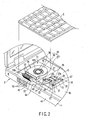
- FIGS. 1 and 2 show a portable computer 1, or an electronic apparatus.
- the portable computer 1 comprises a main unit 2 and a display unit 3 supported on the main unit 2.
- the main unit 2 comprises a housing 4 shaped like a flat box.
- the housing 4 has a bottom wall 4a, a top wall 4b, a front wall 4c and two sidewalls 4d.
- the main unit 2 further comprises a keyboard 5, which is mounted on the top wall 4b.
- the display unit 3 comprises a display housing 6 and a liquid-crystal display panel 7.
- the display panel 7 is set in the display housing 6. Hinges (not shown) couples the display housing 6 to the rear edge of the housing 4, allowing the display housing 6 to rotate.
- the liquid-crystal display panel 7 has a display screen 7a.
- the display screen 7a is exposed through an opening 8 that is made in the front of the display housing 6.
- the housing 4 contains a printed circuit board 10 and a cooling unit 20, the printed circuit board 10 extends along the bottom wall 4a of the housing 4.
- a semiconductor package 11 as a heat generating component is mounted on the upper surface of the printed circuit board 10.
- the package 11 is a microprocessor that is the main component of the portable computer 1.
- the semiconductor package 11 has a base substrate 12 and an IC chip 13.
- the base substrate 12 is soldered to the upper surface of the printed circuit board 10.
- the IC chip 13 is mounted to the center part of the upper surface of the base substrate 12. While operating, the IC chip 13 generates heat in great quantities. The package 11 must therefore be cooled to keep operating in stable conditions.
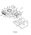
- the cooling unit 20 is designed to cool the semiconductor package 11. As seen from FIGS. 2 to 4, the cooling unit 20 comprises a heat-receiving block 21, a heat sink 22, a heat pipe 23, and a centrifugal air-applying device 24.
- the heat-receiving block 21 is somewhat larger than the IC chip 13.
- a spring member 25 secures the heat-receiving block 21 to the printed circuit board 10.
- the spring member 25 has a pushing plate 26 and four legs 27. Screws 28 fasten the pushing plate 26 to the upper surface of the heat-receiving block 21.
- the legs 27 extend in radial direction from the four corners of the plate 26. Screws 30 fasten the legs 27, at their distal ends, to the four bosses 29 of the printed circuit board 10.
- the legs 27 act as springs, biasing the heat-receiving block 21 toward the semiconductor package 11, the block 21 being secured to the pushing plate 26.
- the heat-receiving block 21 is therefore pushed onto the IC chip 13 and, hence, thermally connected to the IC chip 13.
- the heat sink 22 has a number of heat-radiating fins 32.
- the heat sink 22 lies, extending along the left sidewall 4d of the housing 4, and opposes the exhaust port 33 made in this sidewall 4d.
- the heat pipe 23 is thermally connected at one end 23a to the heat-receiving block 21, and at the other end 23b to the heat sink 22. Therefore, the heat emanating from the IC chip 13 is transmitted to the heat-receiving block 21 and then transferred to the heat sink 22 via the heat pipe 23.
- the centrifugal air-applying device 24 comprises a case 35 and an impeller 36.
- the case 35 is a flat box and contains the impeller 36.
- the case 35 is composed of a case body 37 and a cover 38.
- the case body 37 has a bottom plate 39 and a sidewall 40.
- the sidewall 40 stands from the circumference of the bottom plate 39.
- Both the cover 38 and the bottom plate 39 are shaped like a disc and constitute the outer walls of the case 35.
- the sidewall 40 is bent like an arc, constituting the circumferential wall of the case 35.
- the cover 38 is fixed to the upper edge of the sidewall 40 and opposes the bottom plate 39 of the case body 37.
- the case 35 has two round inlet ports 42a and 42b and one outlet port 43.
- One inlet port 42a is made in the center part of the cover 38, and the other inlet port 42b in the center part of the bottom plate 39.
- a motor support 44 which is shaped like a disc, lies inside the inlet port 42b.
- the inlet ports 42a and 42b oppose each other, spaced apart in the direction of thickness of the case 35.
- the outlet port 43 opens in the sidewall 40 of the case body 37. Its opening is oblong, extending along the diameter of the case 35.
- the case 35 lies on the bottom wall 4a of the housing 4, with the outlet port 43 oriented to the exhaust port 33 of the housing 4.
- the heat sink 22 is positioned, opposing the outlet port 43 of the case 35, and is interposed between the outlet port 43 and the exhaust port 33.
- the impeller 36 has a boss 45 and a plurality of vanes 46.
- the boss 45 is a hollow cylinder.
- the vanes 46 protrude from the circumference of the boss 45, each extending along a tangent to the circumference of the boss 45.
- the impeller 36 lies between the cover 38 and bottom plate 39 of the case 35. It is positioned such that the roots of the vanes 36 oppose the inlet ports 42a and 42b.
- the impeller 36 is coupled to a motor 47, which is secured to the motor support 44.
- the motor 47 can rotate the impeller 36 clockwise as shown in FIGS. 5 and 7.
- a negative pressure develops in the inlet ports 42a and 42b. Air is therefore drawn from outside the case 35, toward the center of the impeller 36 through the inlet ports 42a and 42b as indicated by the arrow in FIG. 6.
- the air thus drawn is applied from the circumference of the impeller 36 by virtue of a centrifugal force.
- the case 35 has a spiral chamber 48 that surrounds the impeller 35.
- the spiral chamber 48 is configured to collect the air applied from the circumference of the impeller 36 and guides the air toward the outlet port 43. It has the function of converting the velocity energy of the air into pressure energy.
- the shape of the spiral chamber 48 is defined by the sidewall 40 of the case body 37. The sidewall 40 surrounds the impeller 36.
- the spiral chamber 48 has an initiating point P1 and a terminating point P2.
- the initiating point P1 is adjacent to one end 43a of the outlet port 43.
- the terminating point P2 deviates from the initiating point P1, by a preset angle ⁇ , in the rotation direction of the impeller 36.
- the other end 43b, which extends along the outlet port 43, is located on a line extending from the terminating point P2.
- the distance d the sidewall 40 and the circumference of the impeller 36 is shortest at the initiating point P1 and gradually increases from the point P1 toward the terminating point P2.
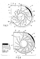
- FIG. 8 represents the pressure distribution that is observed in the case 35 while the impeller 36 is rotating.
- the air pressure (Pa) in the case 36 is lowest at the roots of the vanes 46, which are close to the center of the impeller 36, and also at the position near the outlet port 43.
- the air pressure gradually rises from the initiating point P1 toward the terminating point P2, in the rotation direction of the impeller 36.
- the air pressure (Pa) in the case 35 increases toward the sidewall 40 that is located at the outermost part of the spiral chamber 48.
- the high-pressure region 49 which is defined by the positional relation between the case 35 and the impeller 36, is illustrated in FIG. 7.
- point A is the center of rotation of the impeller 36
- point B is the position of the other end 43b of the outlet port 43
- point C is the position of the one end 43a of the outlet port 43.
- line X connects points B and C
- line Y passes point A and intersects with the line X at right angles
- line Z connects point A and the terminating point P2 of the spiral chamber 48
- point D is the intersection of line Y and the sidewall 40.
- the high-pressure region 47 is region PAD that is defined by the terminating point P2, point A and point D.
- the region PAD lies, with one end reaching terminating point P2 and the other end located at some distance from the midpoint P3 of the spiral chamber 48.
- Two projections 50 are provided on the rims of the inlet ports 42a and 42b, respectively. Both projections 50, which are shaped like an arc, protrude toward the center of rotation (i.e., point A) of the impeller 36.
- the rim of either inlet port is circular and lies coaxial with the impeller 36, except at the projection 50.
- the inlet ports 42a and 42b have a curvature that changes at the high-pressure region 49, due to the projections 50. Neither the inlet port 42a nor the inlet port 42b has a perfectly circular cross section.
- either projection 50 protrudes toward the center of rotation (point A) of the impeller 36, to the greatest extent at its middle part.
- the distance L between the middle part of either projection 50 and the center (point A) is shorter than the distance between any other part of the projection 50 and the center (point A).
- the high-pressure region 49 lies on the line connecting the midpoint of the projection 50 and the center of rotation (point A) of the impeller 36.
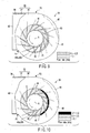
- FIG. 9 illustrates the flow-rate distribution of the air flowing through the inlet ports 42a and 42b of the centrifugal air-applying device 24, which have a non-circular opening.
- FIG. 10 shows the flow-rate distribution of the air flowing through an inlet port, which corresponds to the ports 42a and 42b and which has an opening that is perfectly circular and coaxial with the impeller 36.
- the inlet ports 42a and 42b each having a non-circular opening, reduce both the flow rate of the air flowing a positive pressure and the flow-rate range thereof.
- the inlet port may have a perfectly circular opening coaxial with the impeller. If this is the case, leakage-preventing sheets may be laid on the cover and bottom plate of the case having the inlet ports, thus covering those rim parts of the inlet ports, which correspond to the high-pressure region of the spiral chamber.
- the sheets function as projections protruding from the rim of the inlet ports toward the center of rotation of the impeller.
- the sheets make the either inlet port looks as if having a non-circular opening.
- the sheets prevent the air from leaking at the inlet ports, as the projections do in the first embodiments.
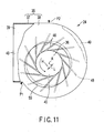
- FIG. 11 depicts the second embodiment of the present invention.
- the second embodiment differs from the first in the shape of inlet ports 55. It is basically the same in other structural aspects as the first embodiment. The components identical to those of the first embodiment are designated at the same reference numerals and will not be described.
- FIG. 11 is a plan view of a centrifugal air-applying device 24, as seen from the cover 38 of the case 35.
- the cover 38 has an inlet port 55, and the bottom plate (not shown) has an inlet port, too.
- the inlet ports 55 have a perfectly circular opening and lie coaxial with each other.
- the inlet ports 55 are eccentric to the center of rotation (point A) of the impeller 36, with their centers located far from the high-pressure region 49 of the spiral chamber 48.
- the inlet ports 55 are eccentric to the impeller 36. Therefore, that rim part of either inlet port 55, which corresponds to the high-pressure region 49, protrudes away from the high-pressure region 49.
- the present invention can prevents air from leaking at inlet ports by using a simple structure.
- the invention can therefore guide air efficiently from the inlet ports to an outlet port, while solving cost-related problems.
Landscapes
- Engineering & Computer Science (AREA)
- General Engineering & Computer Science (AREA)
- Mechanical Engineering (AREA)
- Physics & Mathematics (AREA)
- Theoretical Computer Science (AREA)
- Computer Hardware Design (AREA)
- Human Computer Interaction (AREA)
- General Physics & Mathematics (AREA)
- Thermal Sciences (AREA)
- Structures Of Non-Positive Displacement Pumps (AREA)
- Cooling Or The Like Of Electrical Apparatus (AREA)
Abstract
Description
Claims (13)
- An air-applying device comprising:an impeller which rotates; anda case which contains the impeller and which has at least one circular inlet port configured to guide air to a center of rotation of the impeller and an outlet port configured to collect the air applied from an outer circumference of the impeller, the inlet port having a rim, a projection and an opening, the projection protruding toward the center of rotation of the impeller from that part of the rim which corresponds to a high-pressure region which lies in the case and in which the air attains the highest pressure, and the opening having a non-circular shape.
- An air-applying device comprising:an impeller which rotates; anda case which contains the impeller and which has at least one circular inlet port configured to guide air to a center of rotation of the impeller and an outlet port configured to collect the air applied from an outer circumference of the impeller, the inlet port having a perfectly circular opening, being eccentric to the center of rotation of the impeller and being located away from a high-pressure region which lies in the case and in which the air attains the highest pressure.
- The air-applying device according to claim 1 or claim 2, characterized in that the case has a spiral chamber which surrounds the impeller, collects the air applied from the outer circumference of the impeller and guides the air to the outlet port, and the high-pressure region is located in the spiral chamber.
- The air-applying device according to claim 3, characterized in that the spiral chamber has an initiating point and a terminating point spaced from the initiating point in a direction of rotation of the impeller, and the high-pressure region in the case lies near the terminating point.
- The air-applying device according to claim 3, characterized in that the high-pressure region in the case lies more close to the terminating point than to a midpoint between the initiating and terminating points.
- The air-applying apparatus according to claim 1, characterized in that the opening of the inlet port is circular and coaxial with the impeller, except at a region where the projection protrudes from the rim.
- The air-applying device according to claim 1 or claim 6, characterized in that the high-pressure region in the case lies on a line which extends from the center of rotation of the impeller to the projection.
- The air-applying device according to claim 1 or claim 2, characterized in that the case includes a pair of walls opposing each other across the impeller, and each of the walls has the inlet port.
- A cooling unit comprising:wherein the case has at least one circular inlet port configured to guide air to a center of rotation of the impeller and an outlet port configured to collect the air applied from an outer circumference of the impeller, the inlet port has a rim, a projection and an opening, the projection protrudes toward the center of rotation of the impeller from that part of the rim which corresponds to a high-pressure region which lies in the case and in which the air attains the highest pressure, and the opening has a non-circular shape.a heat sink which is thermally connected to a heat-generating component; andan air-applying device which applies cooling air to the heat sink and which comprises an impeller which rotates and a case which contains the impeller,
- The cooling unit according to claim 9, characterized in that the heat sink is arranged at a position, opposing the outlet port of the air-applying device.
- The cooling unit according to claim 9 or claim 10, characterized in that the case of the air-applying device has a spiral chamber which surrounds the impeller, collects the air applied from the outer circumference of the impeller and guides the air to the outlet port, and the high-pressure region is located in the spiral chamber.
- An electronic apparatus comprising:wherein the case has at least one circular inlet port configured to guide air to a center of rotation of the impeller and an outlet port configured to collect the air applied from an outer circumference of the impeller, the inlet port has a rim, a projection and an opening, the projection protrudes toward the center of rotation of the impeller from that part of the rim which corresponds to a high-pressure region which lies in the case and in which the air attains the highest pressure, and the opening has a non-circular shape.a housing which has a heat-generating component; andan air-applying device which is contained in the housing to cool the heat-generating component and which comprises an impeller which rotates and a case which contains the impeller,
- The electronic apparatus according to claim 12, characterized in that the heat-generating component is thermally connected to the hit sink, and the heat sink is arranged at a position, opposing the outlet port of the air-applying device.
Applications Claiming Priority (1)
| Application Number | Priority Date | Filing Date | Title |
|---|---|---|---|
| PCT/JP2002/013529 WO2004059174A1 (en) | 2002-12-25 | 2002-12-25 | Fan with case having air supplying opening, cooling unit and electronic apparatus comprising fan |
Publications (2)
| Publication Number | Publication Date |
|---|---|
| EP1593853A1 true EP1593853A1 (en) | 2005-11-09 |
| EP1593853A4 EP1593853A4 (en) | 2007-06-27 |
Family
ID=32652507
Family Applications (1)
| Application Number | Title | Priority Date | Filing Date |
|---|---|---|---|
| EP02793387A Withdrawn EP1593853A4 (en) | 2002-12-25 | 2002-12-25 | BOX FAN WITH AIR SUPPLY OPENING, COOLING UNIT AND ELECTRONIC APPARATUS COMPRISING SUCH A FAN |
Country Status (5)
| Country | Link |
|---|---|
| US (1) | US6781835B2 (en) |
| EP (1) | EP1593853A4 (en) |
| JP (1) | JPWO2004059174A1 (en) |
| CN (1) | CN100572824C (en) |
| WO (1) | WO2004059174A1 (en) |
Families Citing this family (71)
| Publication number | Priority date | Publication date | Assignee | Title |
|---|---|---|---|---|
| USD598974S1 (en) | 2004-02-20 | 2009-08-25 | Sloan Valve Company | Automatic bathroom flusher cover |
| CA2458063C (en) | 2003-02-20 | 2013-04-30 | Arichell Technologies, Inc. | Toilet flushers with modular design |
| US6884033B2 (en) * | 2003-09-29 | 2005-04-26 | Cheng Home Electronics Co., Ltd. | Volute inlet of fan |
| USD599886S1 (en) | 2004-02-20 | 2009-09-08 | Sloan Valve Company | Enclosure for automatic bathroom flusher |
| USD602561S1 (en) | 2004-02-20 | 2009-10-20 | Sloan Valve Company | Enclosure for automatic bathroom flusher |
| USD599885S1 (en) | 2004-02-20 | 2009-09-08 | Sloan Valve Company | Enclosure for automatic bathroom flusher |
| JP4551729B2 (en) * | 2004-09-30 | 2010-09-29 | 株式会社東芝 | Cooling device and electronic device having cooling device |
| JP4692919B2 (en) * | 2004-12-16 | 2011-06-01 | 東芝ホームテクノ株式会社 | Blower |
| US7443670B2 (en) * | 2005-01-07 | 2008-10-28 | Intel Corporation | Systems for improved blower fans |
| US7327574B2 (en) * | 2005-02-15 | 2008-02-05 | Inventec Corporation | Heatsink module for electronic device |
| KR100688978B1 (en) * | 2005-04-21 | 2007-03-08 | 삼성전자주식회사 | Projection device |
| US20060260787A1 (en) * | 2005-05-23 | 2006-11-23 | Chaun-Choung Technology Corp. | Flattened contact cooling module |
| KR100628726B1 (en) * | 2005-07-26 | 2006-09-28 | 삼성전자주식회사 | Projection device |
| CN100531535C (en) * | 2005-08-05 | 2009-08-19 | 富准精密工业(深圳)有限公司 | Heat radiation model set |
| US7631686B2 (en) * | 2005-08-25 | 2009-12-15 | Fu Zhun Precision Industry (Shen Zhen) Co., Ltd. | Liquid cooling device |
| US7311494B2 (en) * | 2005-09-08 | 2007-12-25 | Delphi Technologies, Inc. | Fan and scroll design for high efficiency and low noise |
| US9047066B2 (en) * | 2005-09-30 | 2015-06-02 | Intel Corporation | Apparatus and method to efficiently cool a computing device |
| WO2007043119A1 (en) | 2005-09-30 | 2007-04-19 | Fujitsu Limited | Fan device |
| US7262965B2 (en) * | 2005-10-28 | 2007-08-28 | Shuttle Inc. | Thermal structure for electric devices |
| JP2009516386A (en) * | 2005-11-17 | 2009-04-16 | ユニバーシティ・オブ・リムリック | Cooler |
| US7455504B2 (en) * | 2005-11-23 | 2008-11-25 | Hill Engineering | High efficiency fluid movers |
| JP4493611B2 (en) * | 2005-12-13 | 2010-06-30 | 富士通株式会社 | Electronics |
| JP4899523B2 (en) * | 2006-02-20 | 2012-03-21 | 日本電産株式会社 | Centrifugal fan |
| US7486519B2 (en) * | 2006-02-24 | 2009-02-03 | Nvidia Corporation | System for cooling a heat-generating electronic device with increased air flow |
| WO2007102226A1 (en) | 2006-03-09 | 2007-09-13 | Fujitsu Limited | Fan apparatus, electronic apparatus, and control method for them |
| CN101039567B (en) * | 2006-03-17 | 2010-05-12 | 富准精密工业(深圳)有限公司 | Spring plate fixing structure and heat radiation module having the same |
| US7542293B2 (en) * | 2006-04-10 | 2009-06-02 | Fu Zhun Precision Industry (Shen Zhen) Co., Ltd. | Thermal module |
| TW200739327A (en) * | 2006-04-14 | 2007-10-16 | Compal Electronics Inc | Heat dissipating module |
| CN101076236B (en) * | 2006-05-19 | 2010-12-29 | 富准精密工业(深圳)有限公司 | heat sink |
| CN101106888B (en) * | 2006-07-14 | 2012-06-13 | 富准精密工业(深圳)有限公司 | Heat radiation module |
| TWI328997B (en) * | 2006-08-21 | 2010-08-11 | Delta Electronics Inc | Cooling module for use with a projection apparatus |
| US20080043436A1 (en) * | 2006-08-21 | 2008-02-21 | Foxconn Technology Co., Ltd. | Thermal module |
| JP2008071855A (en) * | 2006-09-13 | 2008-03-27 | Fujitsu Ltd | Electronic equipment and printed circuit board unit |
| US7744341B2 (en) * | 2006-12-22 | 2010-06-29 | Fu Zhun Precision Industry (Shen Zhen) Co., Ltd. | Thermal module with centrifugal blower and electronic assembly incorporating the same |
| CN101212885B (en) * | 2006-12-27 | 2011-08-31 | 富准精密工业(深圳)有限公司 | Heat radiation module |
| CN101242732B (en) * | 2007-02-08 | 2011-01-05 | 鸿富锦精密工业(深圳)有限公司 | Heat sink combination |
| US20100128431A1 (en) * | 2007-03-07 | 2010-05-27 | Andre Sloth Eriksen | Hybrid liquid-air cooled graphics display adapter |
| JP2008251687A (en) * | 2007-03-29 | 2008-10-16 | Toshiba Corp | Printed circuit board and electronic device equipped with the same |
| JP2009015385A (en) * | 2007-06-29 | 2009-01-22 | Fujitsu Ltd | Electronic equipment |
| US7957140B2 (en) * | 2007-12-31 | 2011-06-07 | Intel Corporation | Air mover for device surface cooling |
| JP5171295B2 (en) | 2008-02-07 | 2013-03-27 | キヤノン株式会社 | Electrical equipment |
| CN101571739A (en) * | 2008-04-28 | 2009-11-04 | 富准精密工业(深圳)有限公司 | Notebook computer and radiating device thereof |
| TWM357645U (en) * | 2008-10-14 | 2009-05-21 | Asia Vital Components Co Ltd | Water cooling heat-dissipating module |
| US20100103619A1 (en) * | 2008-10-23 | 2010-04-29 | Gamal Refai-Ahmed | Interchangeable Heat Exchanger for a Circuit Board |
| CN101742875B (en) * | 2008-11-20 | 2011-10-05 | 英业达股份有限公司 | Cooling components |
| CN101852237B (en) * | 2009-04-01 | 2013-04-24 | 富准精密工业(深圳)有限公司 | Heat sink and fastener thereof |
| US8405997B2 (en) * | 2009-06-30 | 2013-03-26 | Kabushiki Kaisha Toshiba | Electronic apparatus |
| JP4802272B2 (en) * | 2009-09-30 | 2011-10-26 | 株式会社東芝 | Electronics |
| JP2011081437A (en) * | 2009-10-02 | 2011-04-21 | Toshiba Corp | Electronic equipment |
| WO2011067855A1 (en) * | 2009-12-04 | 2011-06-09 | 富士通株式会社 | Electronic apparatus and heat dissipating module |
| CN102103397A (en) * | 2009-12-21 | 2011-06-22 | 富准精密工业(深圳)有限公司 | Electronic device with centrifugal fan |
| JP5445507B2 (en) * | 2010-06-03 | 2014-03-19 | 株式会社デンソー | Power converter |
| WO2012029128A1 (en) * | 2010-08-31 | 2012-03-08 | 富士通株式会社 | Cooling device, printed circuit board unit, and electronic device |
| JP5002698B2 (en) * | 2010-11-05 | 2012-08-15 | 株式会社東芝 | Television receiver and electronic device |
| TW201232220A (en) * | 2011-01-20 | 2012-08-01 | Acer Inc | Portable electronic device |
| CN102996516B (en) * | 2011-09-19 | 2015-08-05 | 台达电子工业股份有限公司 | Electronic device and its cooling module and its centrifugal fan |
| TW201339808A (en) * | 2012-03-16 | 2013-10-01 | Inventec Corp | Electronic device |
| TW201347646A (en) * | 2012-05-14 | 2013-11-16 | 鴻準精密工業股份有限公司 | Heat sink combination |
| TW201412235A (en) * | 2012-09-14 | 2014-03-16 | Hon Hai Prec Ind Co Ltd | Electronic device |
| USD708591S1 (en) * | 2012-09-22 | 2014-07-08 | Apple Inc. | Fan component |
| US20140116656A1 (en) * | 2012-10-25 | 2014-05-01 | Inhon International Co., Ltd | Heat dissipation module and electronic device with the same |
| TW201424547A (en) * | 2012-12-03 | 2014-06-16 | Hon Hai Prec Ind Co Ltd | Electronic device assembly |
| TW201538063A (en) * | 2014-03-26 | 2015-10-01 | Hon Hai Prec Ind Co Ltd | Electronic device and cooling fan thereof |
| CN105990065A (en) * | 2015-02-10 | 2016-10-05 | 致伸科技股份有限公司 | Keyboard module and notebook computer with same |
| WO2016133014A1 (en) * | 2015-02-19 | 2016-08-25 | 株式会社日本自動車部品総合研究所 | Centrifugal blower |
| US11466190B2 (en) * | 2018-06-25 | 2022-10-11 | Abb Schweiz Ag | Forced air cooling system with phase change material |
| US10667378B1 (en) | 2019-01-14 | 2020-05-26 | Eagle Technology, Llc | Electronic assemblies having embedded passive heat pipes and associated method |
| US11913460B2 (en) * | 2020-03-20 | 2024-02-27 | Greenheck Fan Corporation | Exhaust fan |
| US20240387320A1 (en) * | 2023-05-15 | 2024-11-21 | Cisco Technology, Inc. | Remote heat sink side attach methodology |
| EP4740081A1 (en) * | 2023-09-29 | 2026-05-13 | Google LLC | Differential ports for induced parasitic fluid circulation |
| EP4667754A1 (en) * | 2024-06-21 | 2025-12-24 | Aptiv Technologies AG | Fan cover |
Family Cites Families (21)
| Publication number | Priority date | Publication date | Assignee | Title |
|---|---|---|---|---|
| US3824028A (en) * | 1968-11-07 | 1974-07-16 | Punker Gmbh | Radial blower, especially for oil burners |
| JPS5432806A (en) * | 1977-08-19 | 1979-03-10 | Hitachi Ltd | Multiblade blower |
| SE430092B (en) * | 1982-01-21 | 1983-10-17 | Lennart Wallman | DEVICE FOR RADIAL FLOWERS |
| JPS59105999A (en) * | 1982-12-10 | 1984-06-19 | Hitachi Ltd | Low noise multiblade fan |
| JPS63128297A (en) | 1986-11-19 | 1988-05-31 | 株式会社日立製作所 | Ion exchange type concentrating processor |
| JPS63128297U (en) * | 1987-02-16 | 1988-08-22 | ||
| JP3092267B2 (en) * | 1991-11-28 | 2000-09-25 | ダイキン工業株式会社 | Centrifugal fan |
| JP3069819B2 (en) * | 1992-05-28 | 2000-07-24 | 富士通株式会社 | Heat sink, heat sink fixture used for the heat sink, and portable electronic device using the heat sink |
| JPH06193597A (en) * | 1992-12-24 | 1994-07-12 | Hitachi Ltd | Centrifugal fan |
| JP3700217B2 (en) * | 1995-10-31 | 2005-09-28 | 株式会社デンソー | Centrifugal blower |
| DE19602368A1 (en) * | 1996-01-24 | 1997-07-31 | Sel Alcatel Ag | Radial fan |
| JPH10196596A (en) * | 1997-01-13 | 1998-07-31 | Kokusan Denki Co Ltd | Electric blower |
| JP3081816B2 (en) | 1997-05-23 | 2000-08-28 | 株式会社日本計器製作所 | Fan motor |
| GB2344855B (en) * | 1998-12-14 | 2002-10-09 | Sunonwealth Electr Mach Ind Co | Miniature heat dissipating fans with minimized thickness |
| JP3521423B2 (en) * | 1999-03-31 | 2004-04-19 | 東芝ホームテクノ株式会社 | Fan motor |
| JP4327320B2 (en) * | 2000-01-07 | 2009-09-09 | 株式会社東芝 | Electronics |
| JP2002098096A (en) * | 2000-09-27 | 2002-04-05 | Denso Corp | Centrifugal blower and vehicle air conditioner |
| JP3651379B2 (en) * | 2000-09-28 | 2005-05-25 | ダイキン工業株式会社 | Sirocco fan and humidification unit using the same |
| JP2003023281A (en) * | 2001-07-05 | 2003-01-24 | Toshiba Corp | Electronic equipment with built-in heating element and air-cooled cooling device |
| US6587343B2 (en) * | 2001-08-29 | 2003-07-01 | Sun Microsystems, Inc. | Water-cooled system and method for cooling electronic components |
| EP1406147A1 (en) * | 2002-10-02 | 2004-04-07 | Saint Song Corporation | Computer heat dissipating structure |
-
2002
- 2002-12-25 EP EP02793387A patent/EP1593853A4/en not_active Withdrawn
- 2002-12-25 CN CN02821645.8A patent/CN100572824C/en not_active Expired - Lifetime
- 2002-12-25 JP JP2004562851A patent/JPWO2004059174A1/en not_active Withdrawn
- 2002-12-25 WO PCT/JP2002/013529 patent/WO2004059174A1/en not_active Ceased
-
2003
- 2003-04-25 US US10/424,051 patent/US6781835B2/en not_active Expired - Lifetime
Also Published As
| Publication number | Publication date |
|---|---|
| CN100572824C (en) | 2009-12-23 |
| EP1593853A4 (en) | 2007-06-27 |
| US20040123978A1 (en) | 2004-07-01 |
| JPWO2004059174A1 (en) | 2006-04-27 |
| US6781835B2 (en) | 2004-08-24 |
| CN1578879A (en) | 2005-02-09 |
| WO2004059174A1 (en) | 2004-07-15 |
Similar Documents
| Publication | Publication Date | Title |
|---|---|---|
| US6781835B2 (en) | Air-applying device having a case with an air inlet port, a cooling unit having the air-applying device, and an electronic apparatus having the air-applying device | |
| US6643129B2 (en) | Cooling unit including fan and plurality of air paths and electronic apparatus including the cooling unit | |
| CN100385370C (en) | Heat receivers and electronics | |
| JP3994948B2 (en) | Cooling device and electronic equipment | |
| US6650540B2 (en) | Cooling unit having a heat-receiving section and a cooling fan, and electronic apparatus incorporating the cooling unit | |
| US6579064B2 (en) | Blade for a cooling fan | |
| US20090129020A1 (en) | Electronic apparatus | |
| US20030142476A1 (en) | Centrifugal blower unit having swirl chamber, and electronic apparatus equipped with centrifugal blower unit | |
| US7539009B2 (en) | Cooling unit having a heat radiating portion, and electronic apparatus incorporating a cooling unit | |
| US6118655A (en) | Cooling fan with heat pipe-defined fan housing portion | |
| US7248473B2 (en) | Printed circuit board having larger space for electronic components and contributing to efficient cooling | |
| US8014149B2 (en) | Fan module for electronic device | |
| US20030016495A1 (en) | Cooling unit including plurality of radiating fins and fan for sending air and electronic apparatus with the cooling unit mounted thereon | |
| US20050183848A1 (en) | Coolant tray of liquid based cooling device | |
| US20060279930A1 (en) | Cooling apparatus of liquid-cooling type | |
| US20040027800A1 (en) | Electronic apparatus with a pump to force out liquid coolant | |
| US20050264996A1 (en) | Pump, cooling unit and electronic apparatus including cooling unit | |
| US20050006062A1 (en) | Cooling unit having a plurality of heat-radiating fins, and electronic apparatus with the cooling unit | |
| JP3785098B2 (en) | Electronic device having fan device | |
| JP2007321562A (en) | Centrifugal fan device and electronic device including the same | |
| US20020080579A1 (en) | Cooling unit for cooling a heat-generating component, and electronic apparatus having a cooling unit | |
| US20060254790A1 (en) | Cooling unit having heat radiating portion, through which liquid coolant flows and electronic apparatus equipped with cooling unit | |
| US20050265833A1 (en) | Pump | |
| JP2000214958A (en) | Electronics | |
| JP2003133774A (en) | Cooling equipment and electronics |
Legal Events
| Date | Code | Title | Description |
|---|---|---|---|
| PUAI | Public reference made under article 153(3) epc to a published international application that has entered the european phase |
Free format text: ORIGINAL CODE: 0009012 |
|
| 17P | Request for examination filed |
Effective date: 20040414 |
|
| AK | Designated contracting states |
Kind code of ref document: A1 Designated state(s): DE FR GB |
|
| RAP1 | Party data changed (applicant data changed or rights of an application transferred) |
Owner name: KABUSHIKI KAISHA TOSHIBA |
|
| RIN1 | Information on inventor provided before grant (corrected) |
Inventor name: UCHIYAMA, TOMOSHIGEKABUSHIKI KAISHA TOSHIBA Inventor name: HASHIMOTO, EIJI |
|
| A4 | Supplementary search report drawn up and despatched |
Effective date: 20070530 |
|
| RIC1 | Information provided on ipc code assigned before grant |
Ipc: F04D 29/58 20060101ALI20070523BHEP Ipc: F04D 29/42 20060101AFI20070523BHEP |
|
| 17Q | First examination report despatched |
Effective date: 20071031 |
|
| STAA | Information on the status of an ep patent application or granted ep patent |
Free format text: STATUS: THE APPLICATION IS DEEMED TO BE WITHDRAWN |
|
| 18D | Application deemed to be withdrawn |
Effective date: 20080312 |