EP1593819A1 - Dispositif de fixation d'un anneau brûleur dans une chambre de postcombustion d'un turboréacteur - Google Patents
Dispositif de fixation d'un anneau brûleur dans une chambre de postcombustion d'un turboréacteur Download PDFInfo
- Publication number
- EP1593819A1 EP1593819A1 EP05075890A EP05075890A EP1593819A1 EP 1593819 A1 EP1593819 A1 EP 1593819A1 EP 05075890 A EP05075890 A EP 05075890A EP 05075890 A EP05075890 A EP 05075890A EP 1593819 A1 EP1593819 A1 EP 1593819A1
- Authority
- EP
- European Patent Office
- Prior art keywords
- rod
- plates
- passage
- pin
- locking piece
- Prior art date
- Legal status (The legal status is an assumption and is not a legal conclusion. Google has not performed a legal analysis and makes no representation as to the accuracy of the status listed.)
- Granted
Links
Images


Classifications
-
- F—MECHANICAL ENGINEERING; LIGHTING; HEATING; WEAPONS; BLASTING
- F01—MACHINES OR ENGINES IN GENERAL; ENGINE PLANTS IN GENERAL; STEAM ENGINES
- F01D—NON-POSITIVE DISPLACEMENT MACHINES OR ENGINES, e.g. STEAM TURBINES
- F01D25/00—Component parts, details, or accessories, not provided for in, or of interest apart from, other groups
- F01D25/24—Casings; Casing parts, e.g. diaphragms, casing fastenings
- F01D25/246—Fastening of diaphragms or stator-rings
-
- F—MECHANICAL ENGINEERING; LIGHTING; HEATING; WEAPONS; BLASTING
- F02—COMBUSTION ENGINES; HOT-GAS OR COMBUSTION-PRODUCT ENGINE PLANTS
- F02K—JET-PROPULSION PLANTS
- F02K3/00—Plants including a gas turbine driving a compressor or a ducted fan
- F02K3/08—Plants including a gas turbine driving a compressor or a ducted fan with supplementary heating of the working fluid; Control thereof
- F02K3/10—Plants including a gas turbine driving a compressor or a ducted fan with supplementary heating of the working fluid; Control thereof by after-burners
-
- F—MECHANICAL ENGINEERING; LIGHTING; HEATING; WEAPONS; BLASTING
- F23—COMBUSTION APPARATUS; COMBUSTION PROCESSES
- F23R—GENERATING COMBUSTION PRODUCTS OF HIGH PRESSURE OR HIGH VELOCITY, e.g. GAS-TURBINE COMBUSTION CHAMBERS
- F23R3/00—Continuous combustion chambers using liquid or gaseous fuel
- F23R3/02—Continuous combustion chambers using liquid or gaseous fuel characterised by the air-flow or gas-flow configuration
- F23R3/16—Continuous combustion chambers using liquid or gaseous fuel characterised by the air-flow or gas-flow configuration with devices inside the flame tube or the combustion chamber to influence the air or gas flow
- F23R3/18—Flame stabilising means, e.g. flame holders for after-burners of jet-propulsion plants
- F23R3/20—Flame stabilising means, e.g. flame holders for after-burners of jet-propulsion plants incorporating fuel injection means
Definitions
- the present invention relates to a device for fixing a ring burner on flame-holding arms in a room of afterburner of a turbofan engine.
- the burner ring of a chamber of post-combustion is mounted near a radially end external flame-holder arms that extend into the primary stream leaving the combustion chamber of the turbojet engine.
- the temperature in the chamber of afterburner of the turbojet is at about 1100 ° K in the absence of afterburner and reaches about 2000 ° K in post-combustion mode.
- the burner ring is then subjected to very high temperatures and significant radiation that causes thermal expansion important of its components.
- Fixing the burner ring sectors on the flame holder arms can not be done in a simple way by means of bolts due to the significant thermal expansions of the parts. It takes more that the fastening means used can be used in a reduced space, limited access and preferably without using tools special that would not be easy to handle inside the chamber of afterburner. It is also necessary that these fixing means are protected thermally.
- the purpose of the invention is in particular to provide a simple solution, economic and efficient to these problems.
- a device for fixing a burner ring on flame-holding arms in a post-combustion chamber of a turbojet the burner ring being formed of ring sectors placed substantially end-to-end, characterized in that the ends facing each other consecutive ring sectors are received and guided between two substantially parallel plates with circumferential orientation of the arms flame holders and are immobilized between these plates by pieces engaged between said plates and between the ends ring sectors, said locking pieces being themselves retained between said plates by blocking means engaged in aligned orifices of said plates and said pieces of locking.
- the device according to the invention does not use screws and bolts and allows a three-dimensional free expansion of the ring sectors.
- the assembly and disassembly of the device according to the invention are simple, easy and do not require special tools.
- each locking piece is monobloc and overall shape rounded to avoid any points or protrusions that would act as flame arrestors in post-combustion mode.
- Each locking piece comprises two opposite faces, respectively radially internal and radially external, which are engaged between wings of the ring sectors and which have a shape and a curvature corresponding to those of the wings of the ring sectors.
- the locking parts thus marry the inner shape of the burner ring sectors and effectively maintain these sectors all by allowing their free expansion in post-combustion mode.
- each piece of lock has a through passage oriented radially by relative to the axis of the afterburner and receiving a rod cylindrical whose ends are engaged in the aforementioned orifices of plates of the flame holder arm.
- This rod locks the locking piece and the restraint axial and rotation of the locking piece and ring sectors relative to the flame holder arm.
- the ends of the rod are flush with the surfaces of said plates which are located on the opposite side of the locking piece, so as not to to form points or projections on which the flames in post-combustion mode.
- the device comprises stop means in translation of the rod in the passage passing through the locking part, these means comprising a shoulder formed on the cylindrical surface of the stem and bearing on a shoulder of the inner surface of the passage of the room locking.
- the shoulders of the rod and the passage of the locking piece are eccentric or asymmetrical with respect to the axis of the stem and the passage and thus form means for immobilizing the rod in rotation in the passage.
- the stem comprises a receiving housing of a pin having a first end immobilized in rotation and in translation in said housing and whose second end extends into the aforementioned orifice of one of the plates of the arm flame holder and is retained by means provided on this plate
- the pin makes it possible to complete the locking of the device according to the invention between the plates of the arm.
- Said means provided on the plate advantageously comprise a groove in which the second end of the pin is folded by plastic deformation.
- the housing of the pin in the stem is advantageously in L-shape and has a radial passage receiving the first end of the pin and a longitudinal slot connecting the radial passage to a end of the stem.
- the pin is then easily mounted by translation in the stem, which mounts itself by translation in the passage through the locking piece and into the holes of the plates above.
- the assembly and disassembly of the device are therefore simple and easy to implement.
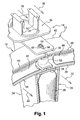
- Figures 1 and 2 are partial views a burner ring formed of sectors 10, 12 carried by arms flame holder 14 of an afterburner chamber of a turbojet engine double flow.
- the flame holder arms 14 extend radially around the axis of the turbojet and comprise a radially outer portion 16 extending into the secondary flow of the turbojet, schematically represented by the arrows 18, and a radially internal portion 20 extending into the primary flow of the turbojet, schematically represented by the arrows 22.
- the arms 14 are regularly spaced the each other and are for example nine in the room of afterburner.
- each arm 14 is formed of a hollow dihedron whose edge 24 is oriented upstream of the turbojet and which is closed on the downstream side by a curved wall 26 forming a screen of thermal protection of a fuel supply ramp 28 which extends radially in the arm 14 from an outer casing of the chamber of afterburner and which includes fuel spray holes oriented for example downstream.
- the radially outer portion of the edge 24 of the dihedral of the arm 14 is usually cut to form a capture opening of a part of the secondary flow 18 and the two side walls 30 of this part of the dihedron are attached to the aforementioned outer casing via legs planes 32 perpendicular to these walls, having holes passage of fastening means of the screw-nut type or the like.
- Each flame holder arm 14 comprises in the vicinity of its radially outer end, two parallel plates 34, 36, respectively radially internal and radially external, oriented circumferential and which serve as support and guidance at the ends of ring sectors 10, 12.
- These plates 34, 36 are of shape approximately rectangular and extend in the axial direction towards the downstream from the arm 14.
- the burner ring sectors 10, 12 have a general shape of dihedral with rounded apex and extend circumferentially around the axis of the afterburner.
- Each sector comprises two wings 38, 40 radially internal and radially external, connected to each other on the upstream side by a vertex rounded 42, the inner wing 38 being substantially cylindrical in shape and centered on the axis of the afterburner chamber while the outer wing 40 is slightly curved in axial section and extends obliquely towards outside from upstream to downstream.
- the plates 34, 36 of the arm 14 are substantially parallel to the wings 38, 40 burner ring sectors 10, 12, in axial sectional view of Figure 2, and in the immediate vicinity of these wings 38, 40.
- An annular fuel rail 44 extends into each burner ring sector and is connected radially to the housing external of the afterburner chamber. It includes holes of fuel spraying downstream and is protected thermally on the downstream side by a curved wall 46 housed between downstream ends of the flanges 38, 40 of each burner ring sector 10, 12.
- a ventilation box 48 is housed in each arm 14 between the edge 24 thereof and the ramp 28 fuel supply that passes between the ends of the burner ring sectors and through an orifice of the internal plate 34 of the arm 14.
- a ventilation box 50 is disposed in each burner ring sector and extends along the ramp 44 between it and the rounded top 42 of the sector. The caissons of ventilation 48, 50 are supplied with air by the part of the secondary flow 18 which is captured by the radially outer portion 16 of each arm 14.
- the temperature of the secondary flow 18 is the order of 200 ° C for example, and that of the primary stream 22 may vary between 800 and 1800 ° C according to the operation of the turbojet engine.
- the circulation of the secondary flow in the arms 14 and in the ring burner allows to cool the ramps 28, 44, the arms 14 and the ring sectors 10, 12, and improve the spraying of fuel in the primary stream 22.
- each comprises a locking piece 52 engaged both between the parallel plates 34, 36 of the arm 14 and between the ends of two ring sectors 10, 12.
- the locking part 52 is retained axially and circumferentially by locking means comprising a rod 54 and a pin 56, inserted in orifices aligned radial plates 34, 36 of the arm 14 and the locking piece 52.
- the plates 34, 36 of the arm 14 comprise aligned orifices 58, 60 in which the ends of the locking means 54, 56.
- the orifice 60 of the radially outer plate 36 is made in a boss 62 radially external, which has a axial groove whose function will be described in the following.
- the circumferential ends facing the wings 38, 40 of the ring sectors 10, 12 are slightly apart from one another for allow the passage of the locking means 54, 56 between them.
- the locking piece 52 of the device according to the invention comprises a through passage 64 substantially cylindrical radially oriented relative to the axis of the turbojet engine and intended to receive the locking means 54, 56 above.
- the locking piece 52 is monobloc and generally shaped rounded, that is to say devoid of points, sharp edges and protrusions which could serve as flame holders.
- This piece 52 constitutes a kind wedge or wedge and comprises two faces 66, 68 opposite radially internal and external respectively, two lateral faces 70, 72, one face upstream 74 and a downstream face 76.
- the radially outer face 68 of the locking piece 52 has a shape and a curvature corresponding to those of the radially outer wing 40 ring sectors 10, 12, and the radially inner face 66 has a planar shape corresponding to that of the radially inner wing 38 of ring sectors 10, 12.
- These faces 66, 68 each comprise an axial groove 78, 80 of shallow depth and delimiting in the faces 66, 68 two support strips on the ends facing the ring sectors 10, 12.
- the grooves 78, 80 allow to ventilate the fastening device of the ring and to limit the friction surfaces between the ring sectors 10, 12 and the piece of lock 52.
- the through passage 64 of part 52 opens substantially in the middle of the grooves 78, 80 of the faces 66, 68 mentioned above.
- the upstream face 74 of the locking piece 52 forms a channel of housing of the annular ramp 44 of the ring burner sector, as this is represented in FIG. 2, and the downstream face 76 has a rounded shape which is substantially in the extension of the aforementioned curved walls 46 forming the thermal protection shield of the ramp 44.
- the lateral faces 70, 72 face the ends of the walls curved above 46, as shown in Figure 1.
- the through passage 64 comprises two cylindrical portions 82, 84 coaxial in diameter different connected by a frustoconical countersink 86.
- the cylindrical portion 82 of larger diameter extends since the internal face 66 over a major part of the height of the piece of lock 52 to the counterbore 86, and the cylindrical portion 84 in diameter smaller extends from the counterbore 86 to the outer face 68 of the workpiece lock 52.
- the rod 54 to be mounted in the through passage 64 of the locking piece 52 is shown in Figures 5 and 6, and has a shape complementary to that of the through-passage 64 of the lock 52. It comprises two cylindrical parts 88, 90 coaxial of different diameters connected by a frustoconical shoulder 92.
- the cylindrical portion 88 of larger diameter extends from the end radially internal of the rod 54 to the shoulder 92, its diameter is slightly smaller than the inner diameter of the larger portion 82 diameter of the passage 64 and its length is greater than that of this part 82 so that its radially inner end can be received in the orifice 58 of the inner plate 34 of the arm 14, as shown in FIG. 2.
- the cylindrical portion 90 of smaller diameter extends into the alignment of the larger diameter portion 88 from the shoulder 92 up to the outer end of the rod 54. Its diameter is slightly less than the inner diameter of the smaller diameter portion 84 of the passage 64 and its length is greater than that of this part 84 so that its radially outer end can be received in the orifice 60 of the outer plate 36 of the arm 14, as shown in FIG.
- the rod 54 is mounted with clearance in the holes 58, 60 of the plates 34, 36 of the arm 14 and in the through passage 64 of the piece of lock 52.
- the rod 54 further comprises a housing for receiving the pin 56 blocking means.
- This accommodation is L-shaped and has a passage 94 radial with respect to the axis of the rod 54 and formed substantially in the middle of the cylindrical portion 88 of larger diameter, and a longitudinal slot 96 connecting the radial passage 94 at the end radially external of the rod 54.
- the pin 56 shown in FIG. 7 is rectilinear cylindrical of small diameter with one end 98 bent at right angles. She is by example in metallic material.
- the pin 56 is intended to be engaged in the housing L of the rod 54, the bent end 98 being received in the radial passage 94 of the rod 54 and the remainder of the pin 56 extending into the slot 96 of the rod 54.
- the pin 56 has a diameter slightly less than the width of the slot 96 of the rod 54 and is mounted with clearance in this one.
- the pin 56 has a length greater than that of the slot 96 so that its free end protrudes axially from the end radially external of the rod 54.
- the rod 54 carrying the pin 56 is engaged in the openings 58, 60 of the plates 34, 36 of the arm 14 and in the through passage 64 of the locking piece 52 until the shoulder 92 of the rod 54 bears on the countersink 86 of the passage 64, the free ends of the rod 54 flush with the surfaces of the plates 34, 36 which are located on the side opposite to the locking piece 52.
- the free end of the pin 56 which protrudes the radially outer end of the rod 54 and the outer plate 36 of the arm 14 is bent at about 90 ° by plastic deformation until it comes in the aforementioned groove of the boss 62 of the orifice 60 of the outer plate 36, as shown in Figures 1 and 2, to immobilize axially and in rotation the rod 54 in the through passage 64 of the locking piece 52.
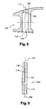
- the pin 56 used is identical to that previously described, the locking piece 100 shown in Figure 8 and the rod 102 shown in Figure 9 being slightly different from those of the first embodiment of device according to the invention.
- the through passage of the piece 100 comprises two cylindrical portions 104, 106 eccentricities of different diameters connected by a surface 108 which is frustoconical on one side and cylindrical on the other side.
- the cylindrical portion 104 of axis 110 which presents a larger diameter, extends from the radially inner face of the piece 100 on much of the height of this piece to the surface 108, and the cylindrical portion 106 of axis 112 having a smaller diameter is off-center relative to the axis 110 and extends from the surface 108 to the face radially external of the locking piece 100.
- the rod 102 has a shape complementary to that of the passage passing through the locking piece 100, and comprises two parts cylindrical 114, 116 non-concentric of different diameters connected by a semi-frustoconical shoulder 118.
- the cylindrical portion 114 of axis 120 which has a large diameter, extends over most of the rod 102 to the shoulder 118, and the cylindrical portion 116 of axis 122 having a smaller diameter is eccentric with respect to the axis 120 and extends outwardly from the shoulder 118.
- the pin 56 shown in FIG. 7, is inserted from the same as previously described in an L-shaped housing 124 formed in the rod 102, the rod 102 being then introduced from the inside of the arm 14, in the orifices 58, 60 of the plates 34, 36 of the arm 14 and in the passage passing through the locking piece 100.
- the locking piece 100 is retained axially downstream by the rod 102 engaged in the aforementioned orifices 58, 60 of the plates 34, 36 of the arm 14, the rod 102 is supported by its shoulder 118 on the surface 108 of the through passage of the piece 100 and the bending at about 90 ° of the end of the pin 56 can axially lock the rod 102 in the through passage of the piece 100.
- the immobilization in rotation of the rod 102 in the passage of the locking part 100 is ensured automatically by the eccentricity of the cylindrical portions 114, 116 of the rod 102 and cylindrical portions 104, 106 of the through passage of the room 100.
Landscapes
- Engineering & Computer Science (AREA)
- Chemical & Material Sciences (AREA)
- Combustion & Propulsion (AREA)
- Mechanical Engineering (AREA)
- General Engineering & Computer Science (AREA)
- Structures Of Non-Positive Displacement Pumps (AREA)
- Control Of Combustion (AREA)
- Connection Of Plates (AREA)
- Finger-Pressure Massage (AREA)
- Processes For Solid Components From Exhaust (AREA)
Abstract
Description
- la figure 1 est une vue schématique partielle en perspective des extrémités de deux secteurs d'anneau brûleur et d'un dispositif de fixation selon l'invention ;
- la figure 2 est une vue schématique partielle en coupe axiale d'un bras accroche-flammes comprenant le dispositif selon l'invention pour la fixation des secteurs d'anneau ;
- la figure 3 est une vue schématique en perspective de la pièce de verrouillage du dispositif selon l'invention ;
- la figure 4 est une vue schématique en coupe axiale de la pièce de verrouillage du dispositif selon l'invention ;
- la figure 5 est une vue schématique en coupe axiale de la tige du dispositif selon l'invention ;
- la figure 6 est une vue en coupe selon la ligne A-A de la figure 5 ;
- la figure 7 est une vue schématique de la goupille utilisée dans le dispositif selon l'invention ;
- la figure 8 est une vue schématique en coupe axiale de la pièce de verrouillage selon une variante de réalisation du dispositif selon l'invention ;
- la figure 9 est une vue schématique en coupe axiale de la tige dans cette variante de réalisation du dispositif selon l'invention.
Claims (14)
- Dispositif de fixation d'un anneau brûleur sur des bras accroche-flammes (14) dans une chambre de postcombustion d'un turboréacteur, l'anneau brûleur étant formé de secteurs d'anneau (10, 12) placés sensiblement bout à bout, caractérisé en ce que les extrémités en regard des secteurs d'anneau (10, 12) consécutifs sont reçues et guidées entre deux plaques (34, 36) sensiblement parallèles à orientation circonférentielle des bras accroche-flammes (14) et sont immobilisées entre ces plaques (34, 36) par des pièces de verrouillage (52) engagées entre lesdites plaques (34, 36) et entre les extrémités en regard des secteurs d'anneau (10, 12), lesdites pièces de verrouillage (52) étant elles-mêmes retenues entre lesdites plaques (34, 36) par des moyens de blocage (54, 56) engagés dans des orifices (58, 60, 64) alignés desdites plaques (34, 36) et desdites pièces de verrouillage (52).
- Dispositif selon la revendication 1, caractérisé en ce que chaque pièce de verrouillage (52) est monobloc et de forme générale arrondie.
- Dispositif selon la revendication 1 ou 2, caractérisé en ce que chaque pièce de verrouillage (52) comprend deux faces (66, 68) opposées, respectivement radialement interne et radialement externe, qui sont engagées entre des ailes (38, 40) des secteurs d'anneau (10, 12) et qui ont une forme et une courbure correspondant à celles des ailes (38, 40) des secteurs d'anneau (10, 12).
- Dispositif selon l'une des revendications précédentes, caractérisé en ce que chaque pièce de verrouillage (52) comporte un passage traversant (64) oriente radialement par rapport à l'axe de la chambre de postcombustion et recevant une tige cylindrique (54) dont les extrémités sont engagées dans les orifices (58, 60) précités des plaques (34, 36) du bras accroche-flammes (14).
- Dispositif selon la revendication 4, caractérisé en ce que les extrémités de la tige (54) affleurent les surfaces desdites plaques (34, 36) qui sont situées du côté opposé à la pièce de verrouillage (52).
- Dispositif selon la revendication 4 ou 5, caractérisé en ce qu'il comprend des moyens d'arrêt en translation de la tige (54) dans le passage traversant (64) de la pièce de verrouillage (52), ces moyens comprenant un épaulement (92) formé sur la surface cylindrique de la tige (54) et venant en appui sur un épaulement de la surface interne du passage (64) de la pièce de verrouillage (52).
- Dispositif selon la revendication 6, caractérisé en ce que les épaulements (118) de la tige (102) et du passage de la pièce de verrouillage (100) sont excentrés ou dissymétriques par rapport à l'axe de la tige (102) et du passage et forment des moyens d'immobilisation de la tige (102) en rotation dans le passage.
- Dispositif selon l'une des revendications 4 à 7, caractérisé en ce que la tige (54) comprend un logement de réception d'une goupille (56) dont une première extrémité (98) est immobilisée en rotation et en translation dans ledit logement et dont la seconde extrémité s'étend dans l'orifice (60) précité d'une des plaques (36) du bras accroche-flammes (14) et est retenue par des moyens prévus sur cette plaque (36).
- Dispositif selon la revendication 8, caractérisé en ce que lesdits moyens prévus sur la plaque (36) comprennent une rainure dans laquelle la seconde extrémité de la goupille (56) est rabattue par déformation plastique.
- Dispositif selon la revendication 8 ou 9, caractérisé en ce que le logement de la goupille (56) dans la tige (54) est en forme de L et comporte un passage radial (94) recevant la première extrémité (98) de la goupille (56) et une fente longitudinale (96) reliant le passage radial (94) à une extrémité de la tige (54).
- Dispositif selon la revendication 10, caractérisé en ce que la fente longitudinale (96) débouche à l'extrémité de la tige (54) qui est engagée dans l'orifice (60) de la plaque radialement externe (36) du bras accroche-flammes (14).
- Dispositif selon l'une des revendications 9 à 11, caractérisé en ce que la rainure recevant l'extrémité rabattue de la goupille (56) est formée dans la plaque radialement externe (36) du bras accroche-flammes (14).
- Dispositif selon l'une des revendications 4 à 12, caractérisé en ce que la tige (54) est montée avec jeu dans le passage traversant (64) de la pièce de verrouillage (52) et dans les orifices (58, 60) des plaques précitées (34, 36).
- Dispositif selon l'une des revendications 8 à 12, caractérisé en ce qu'au montage, la pièce de verrouillage (52) est engagée entre les plaques (34, 36) du bras accroche-flammes (14) et entre les extrémités des secteurs d'anneau (10, 12), la goupille (56) est placée dans le logement de la tige (54), la tige (54) portant la goupille (56) est engagée dans le passage traversant (64) de la pièce de verrouillage (52) et dans les orifices (58, 60) des plaques (34, 36), depuis l'intérieur du bras accroche-flammes (14) et radialement de l'intérieur vers l'extérieur, après quoi l'extrémité extérieure de la goupille (56) est rabattue sur la plaque radialement externe (36) du bras accroche-flammes (14).
Applications Claiming Priority (2)
| Application Number | Priority Date | Filing Date | Title |
|---|---|---|---|
| FR0404798A FR2869954B1 (fr) | 2004-05-05 | 2004-05-05 | Dispositif de fixation d'un anneau bruleur dans une chambre de postcombustion d'un turboreacteur |
| FR0404798 | 2004-05-05 |
Publications (2)
| Publication Number | Publication Date |
|---|---|
| EP1593819A1 true EP1593819A1 (fr) | 2005-11-09 |
| EP1593819B1 EP1593819B1 (fr) | 2006-06-28 |
Family
ID=34938175
Family Applications (1)
| Application Number | Title | Priority Date | Filing Date |
|---|---|---|---|
| EP05075890A Expired - Lifetime EP1593819B1 (fr) | 2004-05-05 | 2005-04-18 | Dispositif de fixation d'un anneau brûleur dans une chambre de postcombustion d'un turboréacteur |
Country Status (8)
| Country | Link |
|---|---|
| US (1) | US7367191B2 (fr) |
| EP (1) | EP1593819B1 (fr) |
| JP (1) | JP4477539B2 (fr) |
| CA (1) | CA2506210A1 (fr) |
| DE (1) | DE602005000030T2 (fr) |
| ES (1) | ES2267085T3 (fr) |
| FR (1) | FR2869954B1 (fr) |
| RU (1) | RU2293861C2 (fr) |
Cited By (1)
| Publication number | Priority date | Publication date | Assignee | Title |
|---|---|---|---|---|
| FR2900460A1 (fr) * | 2006-04-28 | 2007-11-02 | Snecma Sa | Systeme annulaire de post-combustion d'une turbomachine |
Families Citing this family (2)
| Publication number | Priority date | Publication date | Assignee | Title |
|---|---|---|---|---|
| FR2950416B1 (fr) * | 2009-09-23 | 2012-04-20 | Snecma | Dispositif accroche-flammes comprenant un support de bras et un ecran de protection thermique monoblocs |
| JP2017520738A (ja) | 2014-04-09 | 2017-07-27 | ゼネラル・エレクトリック・カンパニイ | 燃焼ライナの補修方法及び装置 |
Citations (4)
| Publication number | Priority date | Publication date | Assignee | Title |
|---|---|---|---|---|
| US5224825A (en) * | 1991-12-26 | 1993-07-06 | General Electric Company | Locator pin retention device for floating joint |
| US5323600A (en) * | 1993-08-03 | 1994-06-28 | General Electric Company | Liner stop assembly for a combustor |
| US5622472A (en) * | 1994-12-21 | 1997-04-22 | Societe Hispano-Suiza | Protective shield for a turbo-engine |
| EP0778408A2 (fr) * | 1995-12-05 | 1997-06-11 | United Technologies Corporation | Chemise de protection pour tubes chauds permettant un remplacement rapide |
Family Cites Families (8)
| Publication number | Priority date | Publication date | Assignee | Title |
|---|---|---|---|---|
| US3236048A (en) * | 1963-09-25 | 1966-02-22 | Gen Motors Corp | Vaporizing manifold and flameholder for afterburners |
| SU908140A1 (ru) * | 1978-06-05 | 1983-12-15 | Предприятие П/Я Г-4561 | Камера сгорани газотурбинного двигател |
| FR2586792B1 (fr) * | 1985-09-03 | 1989-06-16 | Snecma | Dispositif de liaison entre un anneau bruleur ou accroche-flammes en materiau composite et un canal de chambre de post-combustion d'un turboreacteur |
| US4901527A (en) * | 1988-02-18 | 1990-02-20 | General Electric Company | Low turbulence flame holder mount |
| EP0550126A1 (fr) * | 1992-01-02 | 1993-07-07 | General Electric Company | Bouclier thermique pour post-combusteur |
| US6141968A (en) * | 1997-10-29 | 2000-11-07 | Pratt & Whitney Canada Corp. | Fuel nozzle for gas turbine engine with slotted fuel conduits and cover |
| ITMI991209A1 (it) * | 1999-05-31 | 2000-12-01 | Nuovo Pignone Spa | Dispositivo di connessione di un ugello |
| RU2206025C1 (ru) * | 2002-02-14 | 2003-06-10 | Акционерное общество открытого типа Авиамоторный научно-технический комплекс "Союз" | Камера сгорания газотурбинного двигателя |
-
2004
- 2004-05-05 FR FR0404798A patent/FR2869954B1/fr not_active Expired - Fee Related
-
2005
- 2005-04-18 EP EP05075890A patent/EP1593819B1/fr not_active Expired - Lifetime
- 2005-04-18 ES ES05075890T patent/ES2267085T3/es not_active Expired - Lifetime
- 2005-04-18 DE DE602005000030T patent/DE602005000030T2/de not_active Expired - Lifetime
- 2005-04-21 US US11/110,725 patent/US7367191B2/en active Active
- 2005-04-25 JP JP2005125998A patent/JP4477539B2/ja not_active Expired - Fee Related
- 2005-05-02 CA CA002506210A patent/CA2506210A1/fr not_active Abandoned
- 2005-05-04 RU RU2005113683/06A patent/RU2293861C2/ru active
Patent Citations (4)
| Publication number | Priority date | Publication date | Assignee | Title |
|---|---|---|---|---|
| US5224825A (en) * | 1991-12-26 | 1993-07-06 | General Electric Company | Locator pin retention device for floating joint |
| US5323600A (en) * | 1993-08-03 | 1994-06-28 | General Electric Company | Liner stop assembly for a combustor |
| US5622472A (en) * | 1994-12-21 | 1997-04-22 | Societe Hispano-Suiza | Protective shield for a turbo-engine |
| EP0778408A2 (fr) * | 1995-12-05 | 1997-06-11 | United Technologies Corporation | Chemise de protection pour tubes chauds permettant un remplacement rapide |
Cited By (1)
| Publication number | Priority date | Publication date | Assignee | Title |
|---|---|---|---|---|
| FR2900460A1 (fr) * | 2006-04-28 | 2007-11-02 | Snecma Sa | Systeme annulaire de post-combustion d'une turbomachine |
Also Published As
| Publication number | Publication date |
|---|---|
| RU2293861C2 (ru) | 2007-02-20 |
| US7367191B2 (en) | 2008-05-06 |
| US20050247063A1 (en) | 2005-11-10 |
| JP4477539B2 (ja) | 2010-06-09 |
| JP2005321187A (ja) | 2005-11-17 |
| FR2869954A1 (fr) | 2005-11-11 |
| DE602005000030D1 (de) | 2006-08-10 |
| EP1593819B1 (fr) | 2006-06-28 |
| DE602005000030T2 (de) | 2007-01-11 |
| RU2005113683A (ru) | 2006-11-20 |
| FR2869954B1 (fr) | 2006-06-16 |
| ES2267085T3 (es) | 2007-03-01 |
| CA2506210A1 (fr) | 2005-11-05 |
Similar Documents
| Publication | Publication Date | Title |
|---|---|---|
| EP2334909B1 (fr) | Etanchéité entre une chambre de combustion et un distributeur de turbine dans une turbomachine | |
| CA2639206C (fr) | Etage d'aubes a calage variable pour une turbomachine | |
| EP2932051B1 (fr) | Panneaux acoustiques amovibles pour carter de turboreacteur | |
| FR2679010A1 (fr) | Chambre de combustion de turbomachine a bols de prevaporisation demontables. | |
| EP2917519B1 (fr) | Support de tube d'évacuation d'air dans une turbomachine | |
| EP1265035B1 (fr) | Liaison de chambre de combustion CMC de turbomachine en deux parties | |
| EP3775501B1 (fr) | Dispositif de refroidissement pour une turbine d'une turbomachine | |
| EP3775498B1 (fr) | Dispositif de refroidissement pour une turbine d'une turbomachine | |
| FR3004518A1 (fr) | Chambre de combustion annulaire d'une turbomachine | |
| FR3077097A1 (fr) | Dispositif de refroidissement pour une turbine d'une turbomachine | |
| EP3201531B1 (fr) | Chambre de combustion de turbomachine | |
| CA2582624C (fr) | Bras accroche-flammes d'une chambre de post-combustion | |
| FR2998038A1 (fr) | Chambre de combustion pour une turbomachine | |
| FR3009740A1 (fr) | Amelioration pour le verrouillage de pieces de support d'aubage | |
| EP1593819B1 (fr) | Dispositif de fixation d'un anneau brûleur dans une chambre de postcombustion d'un turboréacteur | |
| FR3099801A1 (fr) | Ensemble pour une turbine de turbomachine | |
| FR2915550A1 (fr) | Vanne a clapet pour un systeme de refroidissement dans une turbomachine | |
| EP4010564B1 (fr) | Ensemble visant à maintenir un boîtier collecteur d'un dispositif de refroidissement de carter d'une turbine de turbomachine | |
| EP3455466A1 (fr) | Ensemble pour turbomachine comprenant un distributeur, un élément de structure de turbomachine, et un dispositif de fixation | |
| FR3073581B1 (fr) | Dispositif de maintien d'un organe de prelevement d'air radial centripete | |
| EP3928034B1 (fr) | Chambre de combustion pour une turbomachine | |
| WO2018002480A1 (fr) | Ensemble de fixation d'un distributeur a un element de structure d'une turbomachine | |
| FR2991387A1 (fr) | Turbomachine, telle qu'un turboreacteur ou un turbopropulseur d'avion | |
| EP3857031B1 (fr) | Ensemble annulaire pour turbomachine et procédé de montage de cet ensemble | |
| FR2891862A1 (fr) | Plaque perforee a disposer dans une cavite de refroidissement d'anneau de turbine |
Legal Events
| Date | Code | Title | Description |
|---|---|---|---|
| PUAI | Public reference made under article 153(3) epc to a published international application that has entered the european phase |
Free format text: ORIGINAL CODE: 0009012 |
|
| 17P | Request for examination filed |
Effective date: 20050527 |
|
| AK | Designated contracting states |
Kind code of ref document: A1 Designated state(s): AT BE BG CH CY CZ DE DK EE ES FI FR GB GR HU IE IS IT LI LT LU MC NL PL PT RO SE SI SK TR |
|
| AX | Request for extension of the european patent |
Extension state: AL BA HR LV MK YU |
|
| GRAP | Despatch of communication of intention to grant a patent |
Free format text: ORIGINAL CODE: EPIDOSNIGR1 |
|
| GRAS | Grant fee paid |
Free format text: ORIGINAL CODE: EPIDOSNIGR3 |
|
| GRAA | (expected) grant |
Free format text: ORIGINAL CODE: 0009210 |
|
| AK | Designated contracting states |
Kind code of ref document: B1 Designated state(s): DE ES FR GB IT SE |
|
| PG25 | Lapsed in a contracting state [announced via postgrant information from national office to epo] |
Ref country code: IT Free format text: LAPSE BECAUSE OF FAILURE TO SUBMIT A TRANSLATION OF THE DESCRIPTION OR TO PAY THE FEE WITHIN THE PRESCRIBED TIME-LIMIT;WARNING: LAPSES OF ITALIAN PATENTS WITH EFFECTIVE DATE BEFORE 2007 MAY HAVE OCCURRED AT ANY TIME BEFORE 2007. THE CORRECT EFFECTIVE DATE MAY BE DIFFERENT FROM THE ONE RECORDED. Effective date: 20060628 |
|
| REG | Reference to a national code |
Ref country code: GB Ref legal event code: FG4D Free format text: NOT ENGLISH |
|
| REG | Reference to a national code |
Ref country code: SE Ref legal event code: TRGR |
|
| AKX | Designation fees paid |
Designated state(s): DE ES FR GB IT SE |
|
| REF | Corresponds to: |
Ref document number: 602005000030 Country of ref document: DE Date of ref document: 20060810 Kind code of ref document: P |
|
| GBT | Gb: translation of ep patent filed (gb section 77(6)(a)/1977) |
Effective date: 20060724 |
|
| REG | Reference to a national code |
Ref country code: ES Ref legal event code: FG2A Ref document number: 2267085 Country of ref document: ES Kind code of ref document: T3 |
|
| PLBE | No opposition filed within time limit |
Free format text: ORIGINAL CODE: 0009261 |
|
| STAA | Information on the status of an ep patent application or granted ep patent |
Free format text: STATUS: NO OPPOSITION FILED WITHIN TIME LIMIT |
|
| 26N | No opposition filed |
Effective date: 20070329 |
|
| PGFP | Annual fee paid to national office [announced via postgrant information from national office to epo] |
Ref country code: ES Payment date: 20080404 Year of fee payment: 4 |
|
| PGRI | Patent reinstated in contracting state [announced from national office to epo] |
Ref country code: IT Effective date: 20090601 |
|
| REG | Reference to a national code |
Ref country code: ES Ref legal event code: FD2A Effective date: 20090420 |
|
| PG25 | Lapsed in a contracting state [announced via postgrant information from national office to epo] |
Ref country code: ES Free format text: LAPSE BECAUSE OF NON-PAYMENT OF DUE FEES Effective date: 20090420 |
|
| REG | Reference to a national code |
Ref country code: FR Ref legal event code: PLFP Year of fee payment: 12 |
|
| REG | Reference to a national code |
Ref country code: FR Ref legal event code: PLFP Year of fee payment: 13 |
|
| REG | Reference to a national code |
Ref country code: FR Ref legal event code: CD Owner name: SAFRAN AIRCRAFT ENGINES Effective date: 20170717 |
|
| REG | Reference to a national code |
Ref country code: FR Ref legal event code: PLFP Year of fee payment: 14 |
|
| PGFP | Annual fee paid to national office [announced via postgrant information from national office to epo] |
Ref country code: GB Payment date: 20240320 Year of fee payment: 20 |
|
| PGFP | Annual fee paid to national office [announced via postgrant information from national office to epo] |
Ref country code: SE Payment date: 20240320 Year of fee payment: 20 Ref country code: IT Payment date: 20240320 Year of fee payment: 20 Ref country code: FR Payment date: 20240320 Year of fee payment: 20 |
|
| PGFP | Annual fee paid to national office [announced via postgrant information from national office to epo] |
Ref country code: DE Payment date: 20240320 Year of fee payment: 20 |
|
| REG | Reference to a national code |
Ref country code: DE Ref legal event code: R071 Ref document number: 602005000030 Country of ref document: DE |
|
| REG | Reference to a national code |
Ref country code: GB Ref legal event code: PE20 Expiry date: 20250417 |
|
| REG | Reference to a national code |
Ref country code: SE Ref legal event code: EUG |
|
| PG25 | Lapsed in a contracting state [announced via postgrant information from national office to epo] |
Ref country code: GB Free format text: LAPSE BECAUSE OF EXPIRATION OF PROTECTION Effective date: 20250417 |