EP1593808B1 - Befestigungsvorrichtung für ein oberes Scharnierteil und einen Flügelrahmen - Google Patents
Befestigungsvorrichtung für ein oberes Scharnierteil und einen Flügelrahmen Download PDFInfo
- Publication number
- EP1593808B1 EP1593808B1 EP05009749A EP05009749A EP1593808B1 EP 1593808 B1 EP1593808 B1 EP 1593808B1 EP 05009749 A EP05009749 A EP 05009749A EP 05009749 A EP05009749 A EP 05009749A EP 1593808 B1 EP1593808 B1 EP 1593808B1
- Authority
- EP
- European Patent Office
- Prior art keywords
- hinge
- base portion
- wing
- fastening
- section bar
- Prior art date
- Legal status (The legal status is an assumption and is not a legal conclusion. Google has not performed a legal analysis and makes no representation as to the accuracy of the status listed.)
- Expired - Lifetime
Links
- 238000004873 anchoring Methods 0.000 claims abstract description 15
- 239000000463 material Substances 0.000 description 2
- 229910000831 Steel Inorganic materials 0.000 description 1
- XAGFODPZIPBFFR-UHFFFAOYSA-N aluminium Chemical compound [Al] XAGFODPZIPBFFR-UHFFFAOYSA-N 0.000 description 1
- 229910052782 aluminium Inorganic materials 0.000 description 1
- 239000004411 aluminium Substances 0.000 description 1
- 238000010276 construction Methods 0.000 description 1
- 230000009977 dual effect Effects 0.000 description 1
- 229910001234 light alloy Inorganic materials 0.000 description 1
- 239000010959 steel Substances 0.000 description 1
Images


Classifications
-
- E—FIXED CONSTRUCTIONS
- E06—DOORS, WINDOWS, SHUTTERS, OR ROLLER BLINDS IN GENERAL; LADDERS
- E06B—FIXED OR MOVABLE CLOSURES FOR OPENINGS IN BUILDINGS, VEHICLES, FENCES OR LIKE ENCLOSURES IN GENERAL, e.g. DOORS, WINDOWS, BLINDS, GATES
- E06B3/00—Window sashes, door leaves, or like elements for closing wall or like openings; Layout of fixed or moving closures, e.g. windows in wall or like openings; Features of rigidly-mounted outer frames relating to the mounting of wing frames
- E06B3/96—Corner joints or edge joints for windows, doors, or the like frames or wings
- E06B3/964—Corner joints or edge joints for windows, doors, or the like frames or wings using separate connection pieces, e.g. T-connection pieces
- E06B3/9647—Corner joints or edge joints for windows, doors, or the like frames or wings using separate connection pieces, e.g. T-connection pieces the connecting piece being part of or otherwise linked to the window or door fittings
- E06B3/9648—Mitre joints
-
- E—FIXED CONSTRUCTIONS
- E05—LOCKS; KEYS; WINDOW OR DOOR FITTINGS; SAFES
- E05D—HINGES OR SUSPENSION DEVICES FOR DOORS, WINDOWS OR WINGS
- E05D5/00—Construction of single parts, e.g. the parts for attachment
- E05D5/02—Parts for attachment, e.g. flaps
- E05D5/0215—Parts for attachment, e.g. flaps for attachment to profile members or the like
- E05D5/0223—Parts for attachment, e.g. flaps for attachment to profile members or the like with parts, e.g. screws, extending through the profile wall or engaging profile grooves
- E05D5/0238—Parts for attachment, e.g. flaps for attachment to profile members or the like with parts, e.g. screws, extending through the profile wall or engaging profile grooves with parts engaging profile grooves
-
- E—FIXED CONSTRUCTIONS
- E05—LOCKS; KEYS; WINDOW OR DOOR FITTINGS; SAFES
- E05D—HINGES OR SUSPENSION DEVICES FOR DOORS, WINDOWS OR WINGS
- E05D15/00—Suspension arrangements for wings
- E05D15/48—Suspension arrangements for wings allowing alternative movements
- E05D15/52—Suspension arrangements for wings allowing alternative movements for opening about a vertical as well as a horizontal axis
-
- E—FIXED CONSTRUCTIONS
- E05—LOCKS; KEYS; WINDOW OR DOOR FITTINGS; SAFES
- E05D—HINGES OR SUSPENSION DEVICES FOR DOORS, WINDOWS OR WINGS
- E05D5/00—Construction of single parts, e.g. the parts for attachment
- E05D5/02—Parts for attachment, e.g. flaps
- E05D5/06—Bent flaps
-
- E—FIXED CONSTRUCTIONS
- E05—LOCKS; KEYS; WINDOW OR DOOR FITTINGS; SAFES
- E05Y—INDEXING SCHEME ASSOCIATED WITH SUBCLASSES E05D AND E05F, RELATING TO CONSTRUCTION ELEMENTS, ELECTRIC CONTROL, POWER SUPPLY, POWER SIGNAL OR TRANSMISSION, USER INTERFACES, MOUNTING OR COUPLING, DETAILS, ACCESSORIES, AUXILIARY OPERATIONS NOT OTHERWISE PROVIDED FOR, APPLICATION THEREOF
- E05Y2600/00—Mounting or coupling arrangements for elements provided for in this subclass
- E05Y2600/60—Mounting or coupling members; Accessories therefor
- E05Y2600/626—Plates or brackets
-
- E—FIXED CONSTRUCTIONS
- E05—LOCKS; KEYS; WINDOW OR DOOR FITTINGS; SAFES
- E05Y—INDEXING SCHEME ASSOCIATED WITH SUBCLASSES E05D AND E05F, RELATING TO CONSTRUCTION ELEMENTS, ELECTRIC CONTROL, POWER SUPPLY, POWER SIGNAL OR TRANSMISSION, USER INTERFACES, MOUNTING OR COUPLING, DETAILS, ACCESSORIES, AUXILIARY OPERATIONS NOT OTHERWISE PROVIDED FOR, APPLICATION THEREOF
- E05Y2900/00—Application of doors, windows, wings or fittings thereof
- E05Y2900/10—Application of doors, windows, wings or fittings thereof for buildings or parts thereof
- E05Y2900/13—Type of wing
- E05Y2900/148—Windows
-
- E—FIXED CONSTRUCTIONS
- E06—DOORS, WINDOWS, SHUTTERS, OR ROLLER BLINDS IN GENERAL; LADDERS
- E06B—FIXED OR MOVABLE CLOSURES FOR OPENINGS IN BUILDINGS, VEHICLES, FENCES OR LIKE ENCLOSURES IN GENERAL, e.g. DOORS, WINDOWS, BLINDS, GATES
- E06B3/00—Window sashes, door leaves, or like elements for closing wall or like openings; Layout of fixed or moving closures, e.g. windows in wall or like openings; Features of rigidly-mounted outer frames relating to the mounting of wing frames
- E06B3/32—Arrangements of wings characterised by the manner of movement; Arrangements of movable wings in openings; Features of wings or frames relating solely to the manner of movement of the wing
- E06B3/34—Arrangements of wings characterised by the manner of movement; Arrangements of movable wings in openings; Features of wings or frames relating solely to the manner of movement of the wing with only one kind of movement
- E06B3/36—Arrangements of wings characterised by the manner of movement; Arrangements of movable wings in openings; Features of wings or frames relating solely to the manner of movement of the wing with only one kind of movement with a single vertical axis of rotation at one side of the opening, or swinging through the opening
- E06B3/362—Double winged doors or windows
Definitions
- the present invention relates to the field of accessories for metallic frames for windows.
- a window is normally provided with a fixed frame bearing one or more openable wings.
- the wings can be openable solely by rotation around a vertical axis or can be provided with a dual opening motion, selectable by means of a cremone bolt control which, in addition to the normal rotation around a vertical axis, also provides for opening the wing by rotation around a lower horizontal axis.
- wing means a part of window that is openable solely by rotation around a vertical axis and the term “swivel wing” means a part of window that is openable selectively by rotation around a vertical axis or by rotation around a horizontal axis.
- the present invention was specifically developed for application to a window comprising a wing and a swivel wing.
- the upper hinge of a swivel wing is connected to a scissors arm borne by the upper transverse section bar of the movable frame, whose purpose is to allow the opening motion of the swivel wing around the horizontal axis.
- the fact that the hinge is connected to the scissors arm causes the hinge to be positioned differently relative to the hinge of a wing which is traditionally fastened directly to the vertical section bar of the wing.
- the upper hinge of the wing is positioned differently from the upper hinge of the swivel wing, which is a drawback from the aesthetic viewpoint.
- the object of the present invention is to provide a device for fastening an upper hinge to a frame of a wing set side by side to a swivel-wing, which allows to overcome the aforesaid drawback.
- said object is achieved by a device having the characteristics set out in the claims.
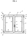
- the reference number 10 designates a window comprising a fixed frame 12, a wing 14 and a swivel wing 16.
- the fixed frame 12 and the frames of the wings 14, 16 are formed by light alloy section bars.
- Each of the two wings 14, 16 has a frame formed by two vertical section bars 18 and by two transverse section bars 20.
- the wings 14, 16 are connected to the fixed frame 12 by means of respective hinges 22 each of which comprises a fixed half-hinge 22' and a movable half-hinge 22".
- the swivel wing 16 comprises a cremone bolt control 24 provided with a handle 26 which is capable of assuming three positions: a closed position, a wing opening position and a swivel wing opening position.
- the wing 14 is solely capable of the movement or rotation around the vertical axis of the hinge 22.
- section bars 18, 20 which constitute the frame of the wing 14 are standardised aluminium section bars and have respective longitudinal grooves 30, 32 with undercut cross section provided with respective external longitudinal edges 34, 36.
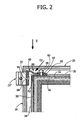
- the reference number 28 designates a device for fastening the movable half-hinge 22" to the frame of the wing 14.
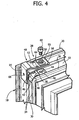
- the fastening device 28 comprises an anchoring plate 38 having a general "L" shape, with a main portion 40 housed in the groove 32 of the upper transverse section bar 20 and a secondary part 42 housed in the groove 30 of the vertical section bar 18.
- the main part 40 of the anchoring plate 38 is provided with a threaded hole 44.
- the anchoring plate 38 is also provided with two through openings 46 positioned between the secondary portion 42 and the fastening hole 44.
- the "L" shape of the anchoring plate 38 allows to obtain a unique positioning of the fastening hole 44 relative to the frame of the wing 14.
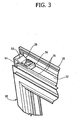
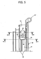
- the fastening device 28 comprises a hinge fastening element 48, comprising a base portion 50, a segment 52 inclined upwards starting from the base portion 50 and a hinge fastening portion 54 which extends orthogonally relative to the base portion 50.
- the base portion 50 is provided at one of its ends with a bent edge 56 which is able to incise the longitudinal edges 36 of the groove 32 in the manner described hereafter.
- the base portion 50 further comprises a smooth through hole 58 through which extends a fastening screw 60 which engages the threaded hole 44 of the anchoring plate 38.
- the base portion 50 is preferably provided on its lower surface with two small projections 62 formed by non-through recesses 64 on the upper surface (see in particular Figures 7 and 8 ).
- the projections 62 are positioned laterally between the hole 58 and the inclined portion 52 and, in the mounting position, are positioned at the inner surfaces of the edges 36.
- the through openings 46 of the anchoring plate 38 are positioned below the projections 62.
- the tightening of the screw 60 thrusts the base portion of the hinge fastening element 48 against the upper surfaces of the edges 36.
- the small projections 62 incise the inner surfaces of the edges 36 and guide the approaching movement of the base portion 50 to the anchoring portion 38 during the tightening of the screw 60.
- the bent edge 56 of the base portion 50 has inclined edges which end with a width that is slightly larger than the distance between the inner surfaces of the edges 36.
- the bent edge 56 incises like a wedge the inner surfaces of the edges 36 and is driven with interference between said edges.
- the material constituting the fastening portion of the hinge 48 has greater hardness than the material constituting the section bars 18, 20.
- the hinge fastening element 48 and the anchoring plate 38 are made of steel.
- the fastening portion of the hinge 54 has a threaded through hole 66 which is engaged by a screw 68 ( Figure 2 ) to fasten the movable half-hinge 22" to the hinge fastening element 48.
- the base portion 50 of the hinge fastening element 48 is pressed against the upper surfaces of the edges 36.
- the hinge fastening portion 54 extends parallel and at a distance with respective to the outer side of the edges, 34 of the vertical section bar 18.
- the movable half-hinge 22" is fastened to the movable frame in the same position as the movable half-hinge of the swivel wing connected to the frame by means of a scissors arm.
- the connection of the half-hinge 22'' to the frame of the wing is particularly robust and stable expecially thanks to the driving of the bent edge 56 into the edges 36 which produces a much more effective anchorage than a simple tightening by friction.
Landscapes
- Engineering & Computer Science (AREA)
- Mechanical Engineering (AREA)
- Civil Engineering (AREA)
- Structural Engineering (AREA)
- Hinges (AREA)
- Window Of Vehicle (AREA)
Claims (3)
- Vorrichtung zum Befestigen einer oberen Gelenkhälfte (22") an einen Rahmen eines Flügels (14), der Seite an Seite mit einem Schwenkflügel (16) eines metallischen Fensterrahmens gesetzt ist, in dem der Rahmen des Flügels (14) zwei vertikale Profilstäbe aufweist (18), die miteinander durch zwei querlaufende Profilstäbe (20) verbunden sind, und in dem die vertikalen und querlaufenden Profilstäbe (18, 20) mit entsprechenden longitudinalen Rillen (30, 32) mit einem hinterschnittenen Abschnitt versehen sind, der mit entsprechenden äußeren longitudinalen Kanten (34, 36) versehen ist, wobei
die Befestigungsvorrichtung (28) eine Verankerungsplatte (38) mit einer im Wesentlichen "L" Form aufweist, die innerhalb der longitudinalen Rillen (30, 32) und an dem Scheitelpunkt zwischen einem vertikalen Profilstab (18) und einem querlaufenden Profilstab (20) anzuordnen ist, wobei die Verankerungsplatte (38) einen Hauptteil (40) aufweist, der dazu vorgesehen ist in der Rille (32) eines oberen querlaufenden Profilstabs (20) aufgenommen zu werden, und einen sekundären Teil (42) aufweist, der dazu vorgesehen ist in der Rille (30) eines vertikalen Profilstabs (18) aufgenommen zu werden, wobei der Hauptteil (40) der Verankerungsplatte (38) mit einem Gewindeloch (44) versehen ist, gekennzeichnet durch
ein Gelenkhälften-Befestigungselement (48) mit einem Basisteil (50), das mittels wenigstens einer Befestigungsschraube (60) an der Verankerungsplatte (38) befestigt ist, wobei das obere Gelenkhälften-Befestigungselement (48) das Basisteil (50) und ein Gelenk-Befestigungsteil (54) aufweist, das senkrecht zu dem Basisteil (50) angeordnet ist, wobei das Basisteil (50) ein glattes Durchgangsloch (58) aufweist, durch das sich die Befestigungsschraube (60) erstreckt, die in das Gewindeloch (44) der Verankerungsplatte (38) eingreift, wobei das Basisteil (50) mit einer gebogenen Kante (56) versehen ist und wobei im Einsatz das Anziehen der Befestigungsschraube (60) das Basisteil (50) des Gelenk-Befestigungselements (48) gegen die obere Oberfläche der longitudinalen Kanten (36) schiebt und die gebogene Kante (56) die longitudinalen Kanten der Rille (32) des querlaufenden Profilstabs (20) einschneidet. - Vorrichtung wie in Anspruch 1 beansprucht, die dadurch gekennzeichnet ist, dass das Gelenkhälften-Befestigungselement (48) einen geneigten Teil (52) aufweist, der sich im Einsatz beginnend von dem Basisteil (50) aufwärts erstreckt.
- Vorrichtung wie in Anspruch 1 beansprucht, dadurch gekennzeichnet, dass das Basisteil (50) des Gelenkhälften-Befestigungselements (48) mit zwei Vorsprüngen (62) auf einer seiner unteren Oberflächen versehen ist, die in einer führender Beziehung mit den longitudinalen Kanten (36) der Rillen (32) zusammenwirken.
Priority Applications (1)
| Application Number | Priority Date | Filing Date | Title |
|---|---|---|---|
| PL05009749T PL1593808T3 (pl) | 2004-05-05 | 2005-05-04 | Urządzenie do mocowania górnej połówki zawiasu do ramy okiennego skrzydła |
Applications Claiming Priority (2)
| Application Number | Priority Date | Filing Date | Title |
|---|---|---|---|
| IT000287A ITTO20040287A1 (it) | 2004-05-05 | 2004-05-05 | Dispositivo per il fissaggio di una semicerniera superiore al telaio di un'anta di finestra. |
| ITTO20040287 | 2004-05-05 |
Publications (3)
| Publication Number | Publication Date |
|---|---|
| EP1593808A2 EP1593808A2 (de) | 2005-11-09 |
| EP1593808A3 EP1593808A3 (de) | 2008-01-23 |
| EP1593808B1 true EP1593808B1 (de) | 2010-06-23 |
Family
ID=34936125
Family Applications (1)
| Application Number | Title | Priority Date | Filing Date |
|---|---|---|---|
| EP05009749A Expired - Lifetime EP1593808B1 (de) | 2004-05-05 | 2005-05-04 | Befestigungsvorrichtung für ein oberes Scharnierteil und einen Flügelrahmen |
Country Status (8)
| Country | Link |
|---|---|
| EP (1) | EP1593808B1 (de) |
| CN (1) | CN100594285C (de) |
| AT (1) | ATE472038T1 (de) |
| DE (1) | DE602005021935D1 (de) |
| ES (1) | ES2346443T3 (de) |
| IT (1) | ITTO20040287A1 (de) |
| PL (1) | PL1593808T3 (de) |
| PT (1) | PT1593808E (de) |
Cited By (1)
| Publication number | Priority date | Publication date | Assignee | Title |
|---|---|---|---|---|
| DE202024106194U1 (de) | 2024-10-29 | 2024-11-12 | Siegenia-Aubi Kg | Schwenklagervorrichtung |
Families Citing this family (3)
| Publication number | Priority date | Publication date | Assignee | Title |
|---|---|---|---|---|
| EP2937504A1 (de) * | 2014-04-22 | 2015-10-28 | Synseal Extrusions Limited | Vorrichtung zur Verwendung auf einer Ecke eines Rahmens |
| CN104018761B (zh) * | 2014-06-03 | 2016-01-20 | 东莞市持力五金有限公司 | 一种合页组件可隐藏的窗户 |
| FR3113082B1 (fr) * | 2020-07-30 | 2022-11-25 | M C France | Menuiserie du type fenêtre ou porte avec un cadre ouvrant équipé d’au moins une équerre de renfort |
Family Cites Families (4)
| Publication number | Priority date | Publication date | Assignee | Title |
|---|---|---|---|---|
| EP0353485A3 (de) * | 1988-07-13 | 1990-05-23 | Elleci S.R.L. | Scharnier zur schnellen Befestigung an Profilelementen von Flügelrahmen oder ähnlichem |
| DE19707496A1 (de) * | 1997-02-25 | 1998-08-27 | Winkhaus Fa August | Flügellagerteil |
| FR2824586B1 (fr) * | 2001-05-10 | 2004-01-30 | Ferco Int Usine Ferrures | Ferrure d'articulation pour ouvrant de porte ou fenetre pivotante et/ou oscillo-battante |
| DE10222731A1 (de) * | 2002-05-23 | 2003-12-04 | Roto Frank Ag | Fenster, Tür od.dgl., Beschlaganordnung sowie Flügel hierfür |
-
2004
- 2004-05-05 IT IT000287A patent/ITTO20040287A1/it unknown
-
2005
- 2005-05-04 EP EP05009749A patent/EP1593808B1/de not_active Expired - Lifetime
- 2005-05-04 DE DE602005021935T patent/DE602005021935D1/de not_active Expired - Lifetime
- 2005-05-04 ES ES05009749T patent/ES2346443T3/es not_active Expired - Lifetime
- 2005-05-04 AT AT05009749T patent/ATE472038T1/de not_active IP Right Cessation
- 2005-05-04 PL PL05009749T patent/PL1593808T3/pl unknown
- 2005-05-04 PT PT05009749T patent/PT1593808E/pt unknown
- 2005-05-05 CN CN200510079231A patent/CN100594285C/zh not_active Expired - Fee Related
Cited By (1)
| Publication number | Priority date | Publication date | Assignee | Title |
|---|---|---|---|---|
| DE202024106194U1 (de) | 2024-10-29 | 2024-11-12 | Siegenia-Aubi Kg | Schwenklagervorrichtung |
Also Published As
| Publication number | Publication date |
|---|---|
| EP1593808A3 (de) | 2008-01-23 |
| DE602005021935D1 (de) | 2010-08-05 |
| EP1593808A2 (de) | 2005-11-09 |
| PT1593808E (pt) | 2010-08-26 |
| CN1702280A (zh) | 2005-11-30 |
| ATE472038T1 (de) | 2010-07-15 |
| ITTO20040287A1 (it) | 2004-08-05 |
| ES2346443T3 (es) | 2010-10-15 |
| PL1593808T3 (pl) | 2010-11-30 |
| CN100594285C (zh) | 2010-03-17 |
Similar Documents
| Publication | Publication Date | Title |
|---|---|---|
| US8087129B2 (en) | Hinges and parts therefor | |
| EP1867821B1 (de) | Treibstangenbeschlag eines Fensters oder einer Tür | |
| EP0112681B1 (de) | Reibungsbeschläge | |
| US6286262B1 (en) | Fitting having support arm or swing arm for supporting a turning sash or a turning-tilting sash | |
| EP1382787A1 (de) | Mitnehmer für ein Kraftfahrzeugfenster | |
| US20040006846A1 (en) | Hinge | |
| US6735823B2 (en) | Hinge | |
| EP2060713A1 (de) | Einbruchsicheres System für Fenster- und Türrahmen | |
| EP1593808B1 (de) | Befestigungsvorrichtung für ein oberes Scharnierteil und einen Flügelrahmen | |
| EP1332901A3 (de) | Rahmenlose und transparente Fahrzeugtür | |
| EP3091150B1 (de) | Schlossanordnung | |
| KR20070014069A (ko) | 윈도우 리프터의 창유리 유지용 조립체 | |
| EP1612356B1 (de) | Scharniervorrichtung für Fenster und Türe | |
| DE102011056416A1 (de) | Anordnung einer Antriebseinheit einer Ausstell- oder Verriegelungseinrichtung | |
| JP2935984B2 (ja) | 面格子の構造と該面格子の組立方法及び該面格子の取付方法 | |
| GB2318613A (en) | A stay for a vent | |
| CN211115505U (zh) | 隐藏式平开上悬五金系统 | |
| EP2987942A1 (de) | Abschirmungsanordnung mit längenverstellbarer seitenschiene mit einem verstärkungsteil und verfahren zur montage solch einer abschirmungsanordnung in einem fensterrahmen | |
| KR102918775B1 (ko) | 도어용 힌지어셈블리 | |
| GB2335701A (en) | A reinforced pivot. | |
| GB2346173A (en) | A laterally adjustable hinge | |
| EP1785563A1 (de) | Satz von Befestigungselementen für Rahmen | |
| WO2007104936A2 (en) | Hinges and parts therefor | |
| AU7142400A (en) | Hinging | |
| JPH0426638Y2 (de) |
Legal Events
| Date | Code | Title | Description |
|---|---|---|---|
| PUAI | Public reference made under article 153(3) epc to a published international application that has entered the european phase |
Free format text: ORIGINAL CODE: 0009012 |
|
| AK | Designated contracting states |
Kind code of ref document: A2 Designated state(s): AT BE BG CH CY CZ DE DK EE ES FI FR GB GR HU IE IS IT LI LT LU MC NL PL PT RO SE SI SK TR |
|
| AX | Request for extension of the european patent |
Extension state: AL BA HR LV MK YU |
|
| PUAL | Search report despatched |
Free format text: ORIGINAL CODE: 0009013 |
|
| AK | Designated contracting states |
Kind code of ref document: A3 Designated state(s): AT BE BG CH CY CZ DE DK EE ES FI FR GB GR HU IE IS IT LI LT LU MC NL PL PT RO SE SI SK TR |
|
| AX | Request for extension of the european patent |
Extension state: AL BA HR LV MK YU |
|
| 17P | Request for examination filed |
Effective date: 20080331 |
|
| AKX | Designation fees paid |
Designated state(s): AT BE BG CH CY CZ DE DK EE ES FI FR GB GR HU IE IS IT LI LT LU MC NL PL PT RO SE SI SK TR |
|
| 17Q | First examination report despatched |
Effective date: 20081203 |
|
| GRAP | Despatch of communication of intention to grant a patent |
Free format text: ORIGINAL CODE: EPIDOSNIGR1 |
|
| GRAS | Grant fee paid |
Free format text: ORIGINAL CODE: EPIDOSNIGR3 |
|
| GRAA | (expected) grant |
Free format text: ORIGINAL CODE: 0009210 |
|
| AK | Designated contracting states |
Kind code of ref document: B1 Designated state(s): AT BE BG CH CY CZ DE DK EE ES FI FR GB GR HU IE IS IT LI LT LU MC NL PL PT RO SE SI SK TR |
|
| REG | Reference to a national code |
Ref country code: CH Ref legal event code: EP |
|
| REG | Reference to a national code |
Ref country code: IE Ref legal event code: FG4D |
|
| REF | Corresponds to: |
Ref document number: 602005021935 Country of ref document: DE Date of ref document: 20100805 Kind code of ref document: P |
|
| REG | Reference to a national code |
Ref country code: PT Ref legal event code: SC4A Free format text: AVAILABILITY OF NATIONAL TRANSLATION Effective date: 20100819 |
|
| REG | Reference to a national code |
Ref country code: GR Ref legal event code: EP Ref document number: 20100401787 Country of ref document: GR |
|
| REG | Reference to a national code |
Ref country code: ES Ref legal event code: FG2A Ref document number: 2346443 Country of ref document: ES Kind code of ref document: T3 |
|
| REG | Reference to a national code |
Ref country code: NL Ref legal event code: VDEP Effective date: 20100623 |
|
| PG25 | Lapsed in a contracting state [announced via postgrant information from national office to epo] |
Ref country code: LT Free format text: LAPSE BECAUSE OF FAILURE TO SUBMIT A TRANSLATION OF THE DESCRIPTION OR TO PAY THE FEE WITHIN THE PRESCRIBED TIME-LIMIT Effective date: 20100623 Ref country code: SE Free format text: LAPSE BECAUSE OF FAILURE TO SUBMIT A TRANSLATION OF THE DESCRIPTION OR TO PAY THE FEE WITHIN THE PRESCRIBED TIME-LIMIT Effective date: 20100623 |
|
| LTIE | Lt: invalidation of european patent or patent extension |
Effective date: 20100623 |
|
| PG25 | Lapsed in a contracting state [announced via postgrant information from national office to epo] |
Ref country code: AT Free format text: LAPSE BECAUSE OF FAILURE TO SUBMIT A TRANSLATION OF THE DESCRIPTION OR TO PAY THE FEE WITHIN THE PRESCRIBED TIME-LIMIT Effective date: 20100623 Ref country code: FI Free format text: LAPSE BECAUSE OF FAILURE TO SUBMIT A TRANSLATION OF THE DESCRIPTION OR TO PAY THE FEE WITHIN THE PRESCRIBED TIME-LIMIT Effective date: 20100623 Ref country code: SI Free format text: LAPSE BECAUSE OF FAILURE TO SUBMIT A TRANSLATION OF THE DESCRIPTION OR TO PAY THE FEE WITHIN THE PRESCRIBED TIME-LIMIT Effective date: 20100623 |
|
| REG | Reference to a national code |
Ref country code: PL Ref legal event code: T3 |
|
| PG25 | Lapsed in a contracting state [announced via postgrant information from national office to epo] |
Ref country code: NL Free format text: LAPSE BECAUSE OF FAILURE TO SUBMIT A TRANSLATION OF THE DESCRIPTION OR TO PAY THE FEE WITHIN THE PRESCRIBED TIME-LIMIT Effective date: 20100623 Ref country code: EE Free format text: LAPSE BECAUSE OF FAILURE TO SUBMIT A TRANSLATION OF THE DESCRIPTION OR TO PAY THE FEE WITHIN THE PRESCRIBED TIME-LIMIT Effective date: 20100623 |
|
| PG25 | Lapsed in a contracting state [announced via postgrant information from national office to epo] |
Ref country code: SK Free format text: LAPSE BECAUSE OF FAILURE TO SUBMIT A TRANSLATION OF THE DESCRIPTION OR TO PAY THE FEE WITHIN THE PRESCRIBED TIME-LIMIT Effective date: 20100623 Ref country code: IS Free format text: LAPSE BECAUSE OF FAILURE TO SUBMIT A TRANSLATION OF THE DESCRIPTION OR TO PAY THE FEE WITHIN THE PRESCRIBED TIME-LIMIT Effective date: 20101023 Ref country code: RO Free format text: LAPSE BECAUSE OF FAILURE TO SUBMIT A TRANSLATION OF THE DESCRIPTION OR TO PAY THE FEE WITHIN THE PRESCRIBED TIME-LIMIT Effective date: 20100623 Ref country code: CZ Free format text: LAPSE BECAUSE OF FAILURE TO SUBMIT A TRANSLATION OF THE DESCRIPTION OR TO PAY THE FEE WITHIN THE PRESCRIBED TIME-LIMIT Effective date: 20100623 Ref country code: CY Free format text: LAPSE BECAUSE OF FAILURE TO SUBMIT A TRANSLATION OF THE DESCRIPTION OR TO PAY THE FEE WITHIN THE PRESCRIBED TIME-LIMIT Effective date: 20100623 |
|
| PG25 | Lapsed in a contracting state [announced via postgrant information from national office to epo] |
Ref country code: DK Free format text: LAPSE BECAUSE OF FAILURE TO SUBMIT A TRANSLATION OF THE DESCRIPTION OR TO PAY THE FEE WITHIN THE PRESCRIBED TIME-LIMIT Effective date: 20100623 |
|
| PLBE | No opposition filed within time limit |
Free format text: ORIGINAL CODE: 0009261 |
|
| STAA | Information on the status of an ep patent application or granted ep patent |
Free format text: STATUS: NO OPPOSITION FILED WITHIN TIME LIMIT |
|
| 26N | No opposition filed |
Effective date: 20110324 |
|
| REG | Reference to a national code |
Ref country code: DE Ref legal event code: R097 Ref document number: 602005021935 Country of ref document: DE Effective date: 20110323 |
|
| PG25 | Lapsed in a contracting state [announced via postgrant information from national office to epo] |
Ref country code: MC Free format text: LAPSE BECAUSE OF NON-PAYMENT OF DUE FEES Effective date: 20110531 |
|
| REG | Reference to a national code |
Ref country code: CH Ref legal event code: PL |
|
| PG25 | Lapsed in a contracting state [announced via postgrant information from national office to epo] |
Ref country code: LI Free format text: LAPSE BECAUSE OF NON-PAYMENT OF DUE FEES Effective date: 20110531 Ref country code: CH Free format text: LAPSE BECAUSE OF NON-PAYMENT OF DUE FEES Effective date: 20110531 |
|
| REG | Reference to a national code |
Ref country code: IE Ref legal event code: MM4A |
|
| PG25 | Lapsed in a contracting state [announced via postgrant information from national office to epo] |
Ref country code: IE Free format text: LAPSE BECAUSE OF NON-PAYMENT OF DUE FEES Effective date: 20110504 |
|
| PG25 | Lapsed in a contracting state [announced via postgrant information from national office to epo] |
Ref country code: LU Free format text: LAPSE BECAUSE OF NON-PAYMENT OF DUE FEES Effective date: 20110504 |
|
| PGFP | Annual fee paid to national office [announced via postgrant information from national office to epo] |
Ref country code: GB Payment date: 20130501 Year of fee payment: 9 Ref country code: DE Payment date: 20130515 Year of fee payment: 9 |
|
| PGFP | Annual fee paid to national office [announced via postgrant information from national office to epo] |
Ref country code: GR Payment date: 20130412 Year of fee payment: 9 Ref country code: FR Payment date: 20130531 Year of fee payment: 9 Ref country code: TR Payment date: 20130424 Year of fee payment: 9 Ref country code: PT Payment date: 20130503 Year of fee payment: 9 Ref country code: PL Payment date: 20130412 Year of fee payment: 9 |
|
| PG25 | Lapsed in a contracting state [announced via postgrant information from national office to epo] |
Ref country code: BG Free format text: LAPSE BECAUSE OF FAILURE TO SUBMIT A TRANSLATION OF THE DESCRIPTION OR TO PAY THE FEE WITHIN THE PRESCRIBED TIME-LIMIT Effective date: 20100923 |
|
| PG25 | Lapsed in a contracting state [announced via postgrant information from national office to epo] |
Ref country code: HU Free format text: LAPSE BECAUSE OF FAILURE TO SUBMIT A TRANSLATION OF THE DESCRIPTION OR TO PAY THE FEE WITHIN THE PRESCRIBED TIME-LIMIT Effective date: 20100623 |
|
| REG | Reference to a national code |
Ref country code: PT Ref legal event code: MM4A Free format text: LAPSE DUE TO NON-PAYMENT OF FEES Effective date: 20141104 |
|
| REG | Reference to a national code |
Ref country code: DE Ref legal event code: R119 Ref document number: 602005021935 Country of ref document: DE |
|
| GBPC | Gb: european patent ceased through non-payment of renewal fee |
Effective date: 20140504 |
|
| PG25 | Lapsed in a contracting state [announced via postgrant information from national office to epo] |
Ref country code: GR Free format text: LAPSE BECAUSE OF NON-PAYMENT OF DUE FEES Effective date: 20141203 Ref country code: PT Free format text: LAPSE BECAUSE OF NON-PAYMENT OF DUE FEES Effective date: 20141104 |
|
| REG | Reference to a national code |
Ref country code: GR Ref legal event code: ML Ref document number: 20100401787 Country of ref document: GR Effective date: 20141203 |
|
| REG | Reference to a national code |
Ref country code: DE Ref legal event code: R119 Ref document number: 602005021935 Country of ref document: DE Effective date: 20141202 |
|
| REG | Reference to a national code |
Ref country code: FR Ref legal event code: ST Effective date: 20150130 |
|
| PG25 | Lapsed in a contracting state [announced via postgrant information from national office to epo] |
Ref country code: DE Free format text: LAPSE BECAUSE OF NON-PAYMENT OF DUE FEES Effective date: 20141202 |
|
| PG25 | Lapsed in a contracting state [announced via postgrant information from national office to epo] |
Ref country code: FR Free format text: LAPSE BECAUSE OF NON-PAYMENT OF DUE FEES Effective date: 20140602 Ref country code: GB Free format text: LAPSE BECAUSE OF NON-PAYMENT OF DUE FEES Effective date: 20140504 |
|
| PG25 | Lapsed in a contracting state [announced via postgrant information from national office to epo] |
Ref country code: PL Free format text: LAPSE BECAUSE OF NON-PAYMENT OF DUE FEES Effective date: 20140504 |
|
| PGFP | Annual fee paid to national office [announced via postgrant information from national office to epo] |
Ref country code: BE Payment date: 20150514 Year of fee payment: 11 |
|
| REG | Reference to a national code |
Ref country code: PL Ref legal event code: LAPE |
|
| PG25 | Lapsed in a contracting state [announced via postgrant information from national office to epo] |
Ref country code: BE Free format text: LAPSE BECAUSE OF NON-PAYMENT OF DUE FEES Effective date: 20160531 |
|
| PG25 | Lapsed in a contracting state [announced via postgrant information from national office to epo] |
Ref country code: TR Free format text: LAPSE BECAUSE OF NON-PAYMENT OF DUE FEES Effective date: 20140504 |
|
| PGFP | Annual fee paid to national office [announced via postgrant information from national office to epo] |
Ref country code: ES Payment date: 20170626 Year of fee payment: 13 |
|
| PGFP | Annual fee paid to national office [announced via postgrant information from national office to epo] |
Ref country code: IT Payment date: 20190513 Year of fee payment: 15 |
|
| REG | Reference to a national code |
Ref country code: ES Ref legal event code: FD2A Effective date: 20190913 |
|
| PG25 | Lapsed in a contracting state [announced via postgrant information from national office to epo] |
Ref country code: ES Free format text: LAPSE BECAUSE OF NON-PAYMENT OF DUE FEES Effective date: 20180505 |
|
| PG25 | Lapsed in a contracting state [announced via postgrant information from national office to epo] |
Ref country code: IT Free format text: LAPSE BECAUSE OF NON-PAYMENT OF DUE FEES Effective date: 20200504 |