EP1593586A2 - Structural system for a convertible automotive vehicle - Google Patents
Structural system for a convertible automotive vehicle Download PDFInfo
- Publication number
- EP1593586A2 EP1593586A2 EP05000703A EP05000703A EP1593586A2 EP 1593586 A2 EP1593586 A2 EP 1593586A2 EP 05000703 A EP05000703 A EP 05000703A EP 05000703 A EP05000703 A EP 05000703A EP 1593586 A2 EP1593586 A2 EP 1593586A2
- Authority
- EP
- European Patent Office
- Prior art keywords
- structural
- vehicle
- pillar
- automotive vehicle
- reinforcement
- Prior art date
- Legal status (The legal status is an assumption and is not a legal conclusion. Google has not performed a legal analysis and makes no representation as to the accuracy of the status listed.)
- Withdrawn
Links
Images


Classifications
-
- B—PERFORMING OPERATIONS; TRANSPORTING
- B60—VEHICLES IN GENERAL
- B60J—WINDOWS, WINDSCREENS, NON-FIXED ROOFS, DOORS, OR SIMILAR DEVICES FOR VEHICLES; REMOVABLE EXTERNAL PROTECTIVE COVERINGS SPECIALLY ADAPTED FOR VEHICLES
- B60J7/00—Non-fixed roofs; Roofs with movable panels, e.g. rotary sunroofs
- B60J7/02—Non-fixed roofs; Roofs with movable panels, e.g. rotary sunroofs of sliding type, e.g. comprising guide shoes
- B60J7/04—Non-fixed roofs; Roofs with movable panels, e.g. rotary sunroofs of sliding type, e.g. comprising guide shoes with rigid plate-like element or elements, e.g. open roofs with harmonica-type folding rigid panels
-
- B—PERFORMING OPERATIONS; TRANSPORTING
- B62—LAND VEHICLES FOR TRAVELLING OTHERWISE THAN ON RAILS
- B62D—MOTOR VEHICLES; TRAILERS
- B62D21/00—Understructures, i.e. chassis frame on which a vehicle body may be mounted
- B62D21/15—Understructures, i.e. chassis frame on which a vehicle body may be mounted having impact absorbing means, e.g. a frame designed to permanently or temporarily change shape or dimension upon impact with another body
- B62D21/157—Understructures, i.e. chassis frame on which a vehicle body may be mounted having impact absorbing means, e.g. a frame designed to permanently or temporarily change shape or dimension upon impact with another body for side impacts
-
- B—PERFORMING OPERATIONS; TRANSPORTING
- B62—LAND VEHICLES FOR TRAVELLING OTHERWISE THAN ON RAILS
- B62D—MOTOR VEHICLES; TRAILERS
- B62D25/00—Superstructure or monocoque structure sub-units; Parts or details thereof not otherwise provided for
-
- B—PERFORMING OPERATIONS; TRANSPORTING
- B62—LAND VEHICLES FOR TRAVELLING OTHERWISE THAN ON RAILS
- B62D—MOTOR VEHICLES; TRAILERS
- B62D25/00—Superstructure or monocoque structure sub-units; Parts or details thereof not otherwise provided for
- B62D25/02—Side panels
- B62D25/025—Side sills thereof
-
- B—PERFORMING OPERATIONS; TRANSPORTING
- B62—LAND VEHICLES FOR TRAVELLING OTHERWISE THAN ON RAILS
- B62D—MOTOR VEHICLES; TRAILERS
- B62D25/00—Superstructure or monocoque structure sub-units; Parts or details thereof not otherwise provided for
- B62D25/20—Floors or bottom sub-units
- B62D25/2009—Floors or bottom sub-units in connection with other superstructure subunits
- B62D25/2036—Floors or bottom sub-units in connection with other superstructure subunits the subunits being side panels, sills or pillars
-
- B—PERFORMING OPERATIONS; TRANSPORTING
- B60—VEHICLES IN GENERAL
- B60R—VEHICLES, VEHICLE FITTINGS, OR VEHICLE PARTS, NOT OTHERWISE PROVIDED FOR
- B60R21/00—Arrangements or fittings on vehicles for protecting or preventing injuries to occupants or pedestrians in case of accidents or other traffic risks
- B60R21/02—Occupant safety arrangements or fittings, e.g. crash pads
- B60R21/16—Inflatable occupant restraints or confinements designed to inflate upon impact or impending impact, e.g. air bags
- B60R21/23—Inflatable members
- B60R21/231—Inflatable members characterised by their shape, construction or spatial configuration
- B60R2021/23153—Inflatable members characterised by their shape, construction or spatial configuration specially adapted for rear seat passengers
Definitions
- the present invention generally relates to automotive vehicle structure and more particularly to a cross-vehicle structural reinforcement for an automotive vehicle.
- Cross-vehicle body stiffness within automotive vehicles is important in reducing torsional twist and vibration of the body, but also improves the ride and handling of the vehicle. This issue is especially important for convertible vehicles where the removal of the traditional fixed roof structure further decreases vehicle stiffness to the point where four door convertible roof vehicles have been essentially impractical to achieve with conventional body structure.
- U.S. Federal Motor Vehicle Safety Standard (“FMVSS”) 214 relates to side impact collision protection for vehicles. This govemmental standard employs a moving barrier, equivalent to a truck bumper, which impacts the vehicle generally at and below a belt-line of the front door and B-pillar. FMVSS 214 puts an added premium on cross-vehicle stiffness.
- a structural reinforcement system for an automotive vehicle.
- a structural beam is employed which extends in a cross-vehicle direction spaced above a vehicle floor.
- a further aspect of the present invention provides a cross-vehicle reinforcement beam inside another structural member.
- a variety of structural beam-to-pillar mounting arrangements are also provided in additional aspects of the present invention.
- Yet another aspect of the present invention uses a structural reinforcement system in a convertible roof vehicle.
- the present invention is advantageous over conventional constructions, in that the present invention significantly improves cross-vehicle resistance to side impact collisions and provides torsional stiffness sufficient for use with a large four door vehicle, such as one having a convertible roof. Spacing the structural beam away from the floor reduces "match boxing" of the vehicle body as compared to traditional, floor mounted reinforcements. Moreover, the beam-to-pillar mounting structures of the present invention significantly enhance side impact resistance as compared to prior constructions. Additional features and advantages of the present invention will be shown and described with reference to the following description and appended figures.
- Figure 1 is a side elevational view showing an alternate embodiment automotive vehicle employing a structural reinforcement system of the present invention, with a hard-top convertible roof in a retracted position and with the left side doors removed;
- Figure 2 is a side elevational view showing an alternate embodiment automotive vehicle employing a structural reinforcement system, with the hard-top convertible roof in a raised position and with the left side doors removed;
- Figure 3 is a perspective view as seen from behind the right rear corner, showing an alternate embodiment automotive vehicle employing a structure reinforcement system of the present invention, with a slidably retracting roof in a raised position;
- Figure 4 is a partially fragmentary, rear diagrammatic view, as seen from line 4-4 of Figure 1, showing the alternate embodiment structural reinforcement system of the present invention
- Figure 5 is a diagrammatic side view showing a first alternate embodiment structural reinforcement system made by stamping
- Figure 6 is a diagrammatic side view showing a second alternate embodiment structural reinforcement system made by hydroforming
- Figure 7 is a perspective view showing a fragmentary third alternate embodiment automotive vehicle employing a structural reinforcement system of the present invention.
- Figure 8 is a diagrammatic, partially cross-sectional view, taken along line 8-8 of Figure 4, showing the second alternate embodiment structural reinforcement system
- Figure 9 is a diagrammatic, cross-sectional view, taken along line 8-8 of Figure 4, showing the first alternate embodiment structural reinforcement system
- Figure 10 is a cross-sectional view taken along line 10-10 of Figure 4, showing the second alternate embodiment structural reinforcement system
- Figure 11 is a cross-sectional view taken along line 10-10 of Figure 4, showing the first alternate embodiment structural reinforcement system
- Figure 12 is a diagrammatic rear view, as seen from line 4-4 of Figure 1, showing a fourth alternate embodiment structural reinforcement system of the present invention
- Figure 13 is a diagrammatic rear view, as seen from line 4-4 of Figure 1, showing a fifth alternate embodiment structural reinforcement system of the present invention
- Figure 14 is a perspective view showing the fifth alternate embodiment structural reinforcement system of the present invention.
- Figure 15 is a diagrammatic rear view, as seen from line 4-4 of Figure 1, showing a sixth alternate embodiment structural reinforcement system of the present invention
- Figure 16 is a diagrammatic top view showing a seventh alternate embodiment structural reinforcement system of the present invention.
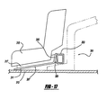
- Figure 17 is a diagrammatic side view showing an eighth alternate embodiment structural reinforcement system of the present invention.
- Figure 18 is a diagrammatic, perspective view showing another alternate embodiment system of the present invention but with a soft top convertible roof;
- Figure 19 is a bottom elevational view showing a first preferred embodiment of the structural system of the present invention.
- Figure 20 is a fragmentary and perspective view showing the first preferred embodiment structural system
- Figure 21 is a fragmentary and rear, elevational view showing the first preferred embodiment structural system
- Figure 22 is a diagrammatic side elevational view showing the first preferred embodiment structural system
- Figure 23 is a diagrammatic top elevational view showing the first preferred embodiment structural system
- Figure 24 is a fragmentary and perspective view showing the first preferred embodiment structural system
- Figure 25 is a cross-sectional view, taken along line 25-25 of Figure 22, showing the first preferred embodiment structural system
- Figure 26 is a cross-sectional view, taken along line 26-26 of Figure 23, showing the first preferred embodiment structural system
- Figure 27 is a fragmentary and perspective view showing a second preferred embodiment of the structural system of the present invention.
- Figure 28 is a rear, diagrammatic view showing the second preferred embodiment structural system
- Figure 29 is a top diagrammatic view showing the second preferred embodiment structural system
- Figure 30 is a rear diagrammatic view showing a ninth alternate embodiment of the present invention structural system.
- Figure 31 is a cross-sectional view, taken along line 26-26 of Figure 23, showing a portion of the preferred embodiment structural system
- Figure 32 is a cross-sectional view, like that of Figure 31, showing a tenth alternate embodiment of the present invention structural system
- Figure 33 is a cross-sectional view, like that of Figure 31, showing an eleventh alternate embodiment of the present invention structural system
- Figure 34 is a rear perspective view showing a twelfth alternate embodiment of the structural system of the present invention.
- Figure 35 is a fragmentary and front, perspective view showing the twelfth alternate embodiment structural system
- Figure 36 is a rear, diagrammatic view showing the twelfth alternate embodiment structural system
- Figure 37 is a rear, diagrammatic view showing a thirteenth alternate embodiment of the present invention structural system
- Figure 38 is a rear, diagrammatic view showing a fourteenth alternate embodiment of the present invention structural system
- Figure 39 is a fragmentary, perspective view showing the fourteenth alternate embodiment structural system
- Figure 40 is a fragmentary, perspective view, like that of Figure 39, showing the fourteenth alternate embodiment structural system with a structural cover plate removed;
- Figure 41 is a cross-sectional view, taken along line 41-41 of Figure 39, showing the fourteenth alternate embodiment structural system
- Figure 42 is a fragmentary, perspective view showing a fifteenth alternate embodiment of the structural system of the present invention.
- Figure 43 is a cross-sectional view, taken along line 43-43 of Figure 42, showing the fifteenth alternate embodiment structural system
- Figure 44 is a fragmentary, rear perspective view showing a sixteenth alternate embodiment of the present invention structural system.
- Figure 45 is a fragmentary and diagrammatic rear view showing a seventeenth alternate embodiment of the present invention structural system.
- An automotive vehicle has a body, a convertible roof and a structural reinforcement system 19.
- the convertible roof is a retractable hard-top roof including a front hard-top section 23, a middle hard-top section 25 and a rear hard-top section 27.
- the hard-top sections are interconnected by a linkage assembly (not shown) driven by an automatic actuator 29, such as an electric motor or hydraulic cylinder.
- the convertible roof is movable from a raised and closed position above front passenger seats 31 and rear passenger seats 33 in a passenger compartment 35, as shown in Figure 2, to a retracted and open position within a roof storage compartment 37, as shown in Figure 1.
- Roof storage compartment 32 is a trunk with a dual opening decklid, or a bootwall, forward and separated from a trunk, covered by an automatically openable tonneau cover.
- Such a hard-top roof and linkage assembly is disclosed in U.S. Patent Serial No. 10/245,973, now U.S. Patent No. 6,695,386, entitled “Vehicle Retractable Hardtop Roof,” which was invented by Michael T. Willard and filed on September 18, 2002, which is incorporated by reference herein.
- a soft top convertible roof 41 is also usable with the present invention, and is disclosed in U.S. Patent Serial No. 10/403,362, now U.S. Patent No. 6,695,385, entitled “Vehicle Convertible Roof,” which was invented by Eric W. Lange and filed on March 31, 2003; this disclosure is incorporated by reference herein.
- Soft top roof 41 includes a top stack mechanism including left and right, front, center and rear side rails, 42, 43 and 44, respectively, with four spanning roof bows 45 and multiple linkages 48.
- An electric motor or hydraulic actuator 46 automatically drives the mechanism and a pliable roof cover 47 is attached to and covers roof bows 45. More preferably, an in-folding soft top convertible roof is employed, such as that disclosed in U.S.
- Figure 3 shows multiple sliding roof panels and a slidably retracting backlite or back window, which are employed with the present invention in another alternate embodiment. This is disclosed in PCT Publication No. WO 02/096685 entitled “Automotive Vehicle with Open Air System” which was invented by Doncov et al. and published on December 5, 2002; this disclosure is also incorporated by reference herein.
- structural reinforcement system 19 is made up of multiple cross-vehicle upper and lower beams 51 and 53, respectively, and interconnected diagonal and vertical beams 55 and 57, respectively.
- Upper beam 51 is positioned adjacent a beltline 61 of the vehicle and lower beam 53 is attached to a sheet metal floor pan 63 of the vehicle.
- the outboard vertical beams 57 are welded, riveted or otherwise secured to B-pillars 65 of the vehicle.
- Beams are integrally hydroformed as a single steel piece, as shown in Figures 4, 6, 8, 10, 12, 13 and 15. In another embodiment, beams are integrally stamped from sheet metal as a single piece, as shown in Figures 5, 9 and 11.
- Gussets 91 are attached to a center tunnel 93 of vehicle and to outboard rocker panels 95 of the unibody vehicle. Alternately, separated created beams can be welded together.
- FIG. 7 and 8 where a polymeric center, floor trim console 101 extends from a front passenger area 107, through a recess 103 in upper beam 51 and into a rear seating area 109, between bucket front seats and bucket rear seats.
- Polymeric trim panels 105 also cover the exterior of structural system 19.
- Door hinge hardware 121 can be secured directly to reinforcement system 19 by bolts, rivets or welding.
- a decorative B-pillar facia 123 is attached to structural system 19 in an alternate embodiment.
- An electronic entertainment system 141 such as including an audio or video compact disc player, movie player, radio or the like, is located in a central pocket of each side of structural system 19 for use by the rear seat passengers.
- an inflatable air bag system 151 may be provided in each pocket of structural system 19, the beams of which are angled to properly channel the deployment forces into the floor and B-pillars.
- roll bars 161 are optionally secured to upper beam 51 on each side of the vehicle's fore-and-aft centerline 162.
- FIG. 13 illustrates a fifth alternate embodiment structural reinforcement system 19 of the present invention.
- This exemplary structural reinforcement system 19 includes an upper beam 161, a lower beam 163, and pairs of crossing diagonal beams 165 and 167 spanning between the upper and lower beams outboard of a middle, recess 169 where upper and lower beams 161 and 163 converge. Ends of upper and lower beams 161 and 163 are directly affixed to adjacent and generally vertical B-pillars 65 and rocker panels 95, without supplemental vertical beams.
- a simulated bumper 171, according to FMVSS 214, is shown adjacent to the vehicle beltline which is generally aligned with the intersection between upper beam 161 and B-pillar 65.
- FIG 14 shows structural reinforcement system 19 with a floor-mounted, trim console 101 centrally extending in a fore-and-aft centerline direction of the vehicle.
- console 101 extends between bucket front seats 173 and either is interrupted by, passes above or passes below beam recess 169.
- the rear end of console 101 terminates forward of a bench rear seat 175.
- a sixth alternate embodiment system 19 is shown in Figure 15.
- a generally straight and horizontal upper beam 181 is connected to a lower beam 183 by multiple branching, intermediate beams 185.
- Lower beam 183 has a raised central segment 187 to circumvent the floor tunnel.
- Beams 181 and 183 are attached to B-pillars 65 and rocker panels 95.
- a central, component cluster assembly 189 is mounted to system 19 within an aperture between the beams for use by the rear seat passengers.
- Component cluster assembly 189 includes audio and video entertainment systems 191, heating/ventilating/air conditioning ducts and controls 193, a storage compartment 195, communications devices 197, and the like.
- a seventh alternate embodiment of a structural reinforcement system 251 includes a structural beam 253 extending in a primarily cross-vehicle direction. Ends 255 of beam 253 are welded or otherwise fastened to B pillars 257. Beam 253 has a pair of arcuately curved segments 259 joining at a forwardly extending central segment 261 which can be optionally secured to a floor panel 263 or fore-and-aft extending tunnel attached thereto, by a generally vertical bracket or gusset.
- a front seat 265 is located forward of each curved segment 259 and each seat back may have a top view curve conforming with the adjacent curved shape of beam 253.
- a floor mounted, interior trim console (such as that shown in Figure 14) may be provided between seats 265 and can either extend above center segment 261 for use by both front and rear seat passengers, may extend below central segment 261 such that the center portion of beam 253 creates an aesthetic styling element in the vehicle as well as providing a functional reinforcement, or a two-piece console may sandwich central segment 261 of beam 253.
- the rear view shape of beam 253 can extend straight across the vehicle or may have a central depression such as that shown in Figures 4 and 7.
- FIG 17 illustrates an eighth alternate embodiment structural reinforcement system 301 of the present invention.
- a structural beam 303 extends in a generally straight (when viewed from the top and rear) orientation between the B-pillars or other upstanding structural members of the automotive vehicle adjacent the rocker panels.
- Beam 303 is an enclosed and hollow polygon, here shown with four sides when viewed in cross-section, which can be created from and extruded or hydroformed steel.
- Rear sections 305 of metal seat tracks 307 are attached to beam 303 by welded or riveted brackets 309.
- Front sections 311 of seat tracks 307 are attached to a metal floor panel 313 by welded, riveted or bolted on brackets.
- Front seats 315, or other passenger seats, and their respective seat movement mechanisms 317 are attached to seat tracks 307.
- Exemplary seat movement mechanisms 317 are disclosed in U.S. Patent No. 5,575,531 entitled “Vehicle Power Seat Adjuster with End Driven Lead Screw Actuation” which issued to Gauger, et al. on November 19, 1996, and is incorporated by reference herein.
- Space is provided below beam 303 and the adjacent portion of seat tracks 307 so as to maximize passenger compartment leg room and foot room.
- Beam 303 is secured to the vehicle well below a belt line area but may be useful in trucks, vans, sport utility vehicles and other situations that serve to add the required vibrational stiffness, minimize cross-vehicle and diagonal twisting of the vehicle body, while also improving crashworthiness during side impact.
- beam 303 advantageously serves as a multifunctional part.
- Figure 19 illustrates supplemental bracing of underbody 331 of an automotive vehicle 333, which includes a structural floor pan 335 and rocker panels 337 and 339.
- the supplemental bracing includes a pair of inwardly angled front braces 341 and 343, a pair of oppositely expanding V-shaped middle braces 345 and 347, a generally flat central brace 349 extending fore and aft of middle braces 345 and 347, and a pair of inwardly angled rear braces 351 and 353.
- a center or B-pillar 361 upwardly projects in a generally vertical manner between front and rear door openings 363 and 365, respectively, from each rocker panel 337 on the outboard sides of floor pan 335.
- Each B-pillar has an inner, stamped steel panel 367, an outer, stamped steel panel 369 and an exterior, polymeric trim molding 371.
- Inner and outer panels 367 and 369 are welded together at flanges 373 and 375, and define an elongated hollow area 377 therebetween.
- Rocker panel 337 is similarly constructed with an inner, stamped steel panel 381 and an outer, stamped steel panel 383, welded together at pinch weld flanges 385 and defining a fore-and-aft elongated hollow area 387 therebetween.
- a generally vertical, steel reinforcing tube 391 is welded to each center pillar 361, within hollow 377, and is attached to a generally fore-and-aft elongated and horizontal reinforcing steel tube 393 which is welded to rocker panel 337 in hollow 387.
- a reinforcement cross beam 401 is welded to a middle segment of vertical reinforcement tube 391 and is elongated in a generally straight, cross-vehicle and horizontal orientation projecting inwardly between the B-pillars 361.
- Cross beam 401 is a structural steel tube.
- An upper diagonal reinforcement tube 403 upwardly and outwardly extends from cross beam 401 and is welded onto an upper segment of vertical reinforcement tube 391, which is considered herein to be part of the B-pillar.
- a lower diagonal reinforcement tube 405 downwardly and outwardly extends from cross beam 401 and is welded to a lower segment of vertical reinforcement tube 391 and/or rocker reinforcement tube 393. Both B-pillar reinforcement systems are similarly constructed in mirrored symmetry to each other and are connected by the continuous cross beam 401.
- a structural outer member 411 is best observed in Figures 21, 24 and 26.
- Structural outer member or supplemental cross beam 411 is preferably shown as two stamped, steel parts that are welded or riveted together to encase or surround a majority of main cross beam 401 therein between B-pillars 361.
- structural outer member 411 may consist of a circular-cylindrical tube or rectangular cross-sectionally shaped reinforcement surrounding cross beam 401.
- cross beam 401 is inwardly spaced from a majority of support outer member 411, and outer member 411 is attached to B-pillars 361 and a floor tunnel 413 by diagonally extending, structural gusset covers 415, 417 and 419.
- Structural outer member 411 serves to reinforce and limit buckling of the otherwise straight cross beam 401 during a side impact collision and to further stiffen the vehicle body between the B-pillars 361 during extreme torsional operating forces of the vehicle.
- Figure 20 shows polymeric, interior trim panels 425 attached to B-pillars 361 and structural outer member 411, which may have fastening holes therein.
- cross beam 401, structural outer member 411, the gusset covers and diagonal tubes 403 and 405 are all aesthetically hidden by interior trim panels 425.
- foot room clearance is provided between the underside of interior trim panels 425, structural outer member 411 and cross beam 401, relative to the spaced apart floor pan 335, as can be observed in Figures 21 and 26.
- This structural system-to-floor spacing further improves side impact resistance and torsional resistance of the vehicle, especially when impacted by a truck or other raised bumper of a colliding vehicle.
- Cross beam 401 is preferably of a hollow and circular cross-sectional configuration, such as that shown in Figures 26 and 31, or it may be filled with a solid yet somewhat compressible foam, such as that shown in Figure 32, filled with a solid polymeric material (not shown), or may have a D-like cross sectional shape such as that illustrated in Figure 33.
- FIG. 27-29 A second preferred embodiment structural system of the present invention is illustrated in Figures 27-29.
- This embodiment is similar to the first preferred embodiment, however, a main cross beam 451 is integrally formed as a single piece with upper diagonal tube 453 and lower diagonal tube 455, such as by hydroforming or sheet stamping. Additionally, fore-and-aft enlarged plates 457, 459 and 461 are welded onto their respective ends of tubes 453 and 455, and beam 451. These plates 457, 459 and 461 are, in turn, screwed or riveted onto box-like stamped or cast brackets 463, 465 and 467 which are secured to a generally vertically extending reinforcement tube 469 welded inside of the center pillar.
- main cross beam 451 can be bolted to a center tunnel 413 as shown in Figure 37.
- Figure 30 shows a ninth alternate embodiment structural system of the present invention wherein a straight and circularly sectioned cross beam 481 extends in a generally horizontal and crosscar direction and is directly coupled to generally vertical reinforcement tubes 483 welded within center pillars 361 and rocker panels 337.
- the center of cross beam 481 is welded to or passes above a centrally located and fore-and-aft elongated floor tunnel 485 of the vehicle.
- Diagonally extending upper and lower reinforcement tubes 487 and 489 couple outboard segments of cross beam 481 to pillar reinforcement tube 483 and a rocker reinforcement tube 491.
- Interior trim panels 493, 495 and 497 aesthetically cover the top, front, back and bottom of cross beam 481, and diagonal upper and lower reinforcement tubes 487 and 489.
- Front passenger seats 499 are located in front of and are independently movable in a fore-and-aft direction and up-down direction with regard to cross beam 481. Unlike with the first preferred embodiment, no surrounding structural member (such as 411 shown in Figure 21) is employed.
- a twelfth alternate embodiment has a first sub-variation shown in Figures 34 and 35.
- a vehicle body, cross beam 501, structural outer reinforcement 502, upper and lower diagonal reinforcement tubes 503 and 505, vertical pillar reinforcement tubes 507 and rocker reinforcement tubes 509 are constructed like that disclosed in the first preferred embodiment, specifically Figures 21 and 26.
- Cross beam 501 and the surrounding structural outer member 502 differ in that they project in a generally straight line through floor tunnel 413 and are mounted inside a coupler 511 secured to floor tunnel 413.
- a second sub-variation of this embodiment provides for a single cross beam 501' but without the supplemental structural outer member.
- additional structural, cross-vehicle panels 513 and 515 are provided at the front windshield header and between the rear wheel houses where the rear seat back panel is located.
- Coupler 525 is secured to floor tunnel 413 internal to a steel, floor tunnel reinforcement cap 527 attached to floor tunnel 413.
- Coupler 525 normally allows clearance of adjacent inboard ends 529 and 531 of cross beams 521 and 523, respectively, such that normal cross-vehicle tolerance variations and temperature induced contraction and expansion are allowed by varied end-to-end spacing of cross beams 521 and 523 within coupling 525.
- a fourteenth preferred embodiment of the present invention structural system is illustrated in Figures 38-41.
- Cross beam 551 is welded to vertically extending pillar reinforcement tube 555.
- a corrugated and diagonally extending, structural gusset 557 upwardly and outwardly projects from structural outer member 553 or alternately, cross beam 551, and is welded or riveted to inner panel 367 of B-pillar 361.
- Gusset 557 has a generally triangularly shaped configuration when viewed from the rear and includes a pair of attached corrugated and stamped steel panels 559 and 561 which are in mirrored symmetry to each other.
- Panels 559 and 561 have outer flanges 563 attached to the inner panel of the B-pillar, and inner flanges 565 attached to a structural, stamped steel gusset cover plate 567 (shown in Figures 39 and 41).
- the corrugations define diagonally extending ribs or flutes within each plate to add torsional stiffness.
- a box-like and generally diagonally extending structural gusset 571 projects from structural outer member 553 in a downward and outwardly angled manner to the bottom of center pillar 361 and rocker panel 337.
- a fifteenth alternate embodiment structural system of the present invention is similar to the configuration employed with the prior alternate embodiment of Figures 38-41, except that a gusset cover plate is not employed and the upper gusset has a differing configuration. More specifically, an upper gusset 601 is defined by a pair of stamped steel gusset plates 603 and 605 which are attached to the inner panel of B-pillar 361.
- Gusset plates 603 and 605 are stamped in mirrored symmetry and each has a generally L-shaped pillar section 607, with an outwardly projecting pinch weld flange, and a corrugated or ribbed section 609 which defines generally circular and hollow flutes when the panels are joined together, thereby adding diagonal structural rigidity between the attached structural outer member 611 and B-pillar 361.
- This diagonal gusset, as well as that of the prior embodiment, are preferably covered by an aesthetically pleasing, polymeric and/or carpeted interior trim panel.
- a sixteenth alternate embodiment structural system of the present invention provides diagonally extending upper reinforcement beams 651 and 653, of a tubular configuration, which attach to either a tubular cross beam 655 and/or surrounding structural outer member 657 immediately adjacent a center, floor tunnel area 659.
- An upper end of each diagonal upper beam 651 and 653 attaches to a portion of each center pillar 631 adjacent beltline 61 (see Figure 1) of the vehicle.
- the upper and outer end of each diagonal tube 651 and 653 may additionally or alternately be welded to a vertically extending pillar reinforcement tube.
- Figure 45 shows a seventeenth alternate embodiment of the present invention structural system wherein an outer coupling 701 has an enlarged flange 703 screwed or riveted to an inner panel of center pillar 761.
- Coupling 701 also has a cylindrical and hollow collar 705 which slidably receives an outboard end of a tubular cross beam 707.
- Coupling 701 is configured to allow cross-vehicle movement of the secured cross beam 707 relative to pillar 361 to account for normal cross-vehicle manufacturing tolerance variations.
- a lost motion screw or pin fastener can optionally extend through an elongated slot in collar 705 and engage within a snug aperture in cross beam 707 to prevent complete disengagement of cross beam 707 from coupling 701 yet allow tolerance variations.
- Structural system 19 is preferably employed in a convertible vehicle having four, side passenger doors 213 but may also be used in a stretch limousine having four or more passenger doors and a stationary roof.
- Bullet-proof armor is optionally mounted along a cross-car plane parallel and internal to trim panels 105. Furthermore, it should be appreciated that alternate beam shapes can be employed. It is intended by the following claims to cover these and any other departures from the disclosed embodiments that fall within the true spirit of the invention.
Landscapes
- Engineering & Computer Science (AREA)
- Mechanical Engineering (AREA)
- Chemical & Material Sciences (AREA)
- Combustion & Propulsion (AREA)
- Transportation (AREA)
- Body Structure For Vehicles (AREA)
Abstract
Description
Claims (69)
- An automotive vehicle apparatus comprising a structural main beam and a structural member surrounding a majority of the main beam, the main beam and member being elongated in a substantially horizontal direction and being substantially parallel to each other.
- The automotive vehicle apparatus of Claim 1 further comprising:a first passenger seating area;a front door located laterally adjacent the first seating area;a second passenger seating area located rearwardly of the first seating area; anda second door located laterally adjacent the second seating area, the second door being located on the same side as and rearwardly of the first door;the main beam and member being located substantially between the first and second seating areas.
- The automotive vehicle apparatus of Claim 2 further comprising a convertible roof movable to a raised position, covering the front and rear seating areas, to a retracted position.
- The automotive vehicle apparatus of Claim 1 further comprising:a substantially vertical body pillar; anda first diagonal beam downwardly extending from a lower side of the main beam to the body pillar.
- The automotive vehicle apparatus of Claim 4 further comprising a second diagonal beam upwardly extending from an upper side of the main beam to the body pillar.
- The automotive vehicle apparatus of Claim 1 wherein the main beam is substantially straight between outboard portions of the vehicle.
- The automotive vehicle apparatus of Claim 1 further comprising aesthetically pleasing interior trim substantially hiding and substantially surrounding a majority of the main beam and the structural member.
- The automotive vehicle apparatus of Claim 1 wherein the main beam and structural member are elongated in a cross-vehicle direction.
- The automotive vehicle apparatus of Claim 1 further comprising a corrugated gusset diagonally extending from the structural member.
- The automotive vehicle apparatus of Claim 1 wherein at least a majority of the main beam is spaced away from the structural member.
- The automotive vehicle apparatus of Claim 1 further comprising:wherein the main beam and the structural member assist the vehicle in satisfactorily passing Federal Motor Vehicle Safety Standard side impact test 214.at least four passenger door openings; andcenter pillars upwardly projecting between adjacent pairs of the door openings, at least one of the main beam and the structural member being rigidly coupled to the pillars;
- The automotive vehicle apparatus of Claim 1 further comprising at least two front seats located in the front seating area, the front seats being independently movable and not restrained by the main beam and the structural member.
- The automotive vehicle apparatus of Claim 1 wherein the main beam is hydroformed metal of substantially circular cross-sectional shape.
- An automotive vehicle comprising:a body having a front seating area with a front seat and a rear seating area with a rear seat;at least one front passenger door opening positioned to allow access to the front seating area;at least one rear passenger door opening positioned to allow access to the rear seating area;a convertible roof movable from a raised position, covering at least one of the seating areas, to a retracted position; anda structural reinforcement beam extending in a substantially cross-vehicle direction substantially between the seating areas, the structural beam having end sections and a middle section, the middle section being straight and substantially horizontal, the front seat being movable independent of the structural beam.
- The automotive vehicle of Claim 14 further comprising:a substantially vertical body pillar; anda first diagonal beam downwardly extending from a lower side of the structural reinforcement beam to the body pillar.
- The automotive vehicle apparatus of Claim 15 further comprising a second diagonal beam upwardly extending from an upper side of the structural reinforcement beam to the body pillar.
- The automotive vehicle of Claim 14 wherein the convertible roof further comprises:an automatic actuator;roof rails and roof bows operably movable by the actuator; anda pliable roof cover attached to the roof bows.
- The automotive vehicle of Claim 14 wherein the convertible roof further comprises:an automatic actuator; andat least one hard-top roof panel operably movable by the actuator.
- The automotive vehicle of Claim 14 further comprising a structural rocker panel attached to the structural beam.
- The automotive vehicle of Claim 14 further comprising a central floor tunnel attached to the structural beam.
- The automotive vehicle of Claim 14 further comprising a corrugated gusset diagonally extending from the structural beam.
- The automotive vehicle of Claim 14 further comprising a vehicle floor,
wherein at least a majority of the structural beam is spaced above the floor. - A structural reinforcement system for an automotive vehicle, the system comprising:a structural, primary beam being elongated in a cross-vehicle direction;a structural, diagonal beam upwardly extending from the primary beam and inclining away from a vehicular, fore-and-aft elongated centerline.
- The system of Claim 23 further comprising a substantially vertical body pillar, the diagonal beam being affixed to the pillar.
- The system of Claim 24 further comprising a substantially vertically extending and structural pillar reinforcement located inside of and affixed to the pillar, the diagonal beam and the primary beam being affixed to the pillar reinforcement.
- The system of Claim 24 wherein the pillar is a B-pillar located between front and rear passenger door openings.
- The system of Claim 23 further comprising a vehicle rocker panel and a second, structural diagonal beam downwardly extending from the primary beam and being affixed adjacent the rocker panel.
- The system of Claim 23 further comprising a raised vehicle floor tunnel, the primary beam being straight between its ends and attaching to the floor tunnel.
- The system of Claim 23 further comprising at least one roll bar coupled to at least one of the beams.
- The system of Claim 23 further comprising an electronic device coupled to at least one of the beams.
- The system of Claim 23 wherein the beams are tubular metal.
- An automotive vehicle apparatus comprising a reinforcement extending in a cross-vehicle direction substantially from one outboard side of the vehicle to the other, the reinforcement including a rigid wall with a substantially closed cross-section filled with a compressible solid material.
- The apparatus of claim 32 further comprising a vehicle floor, wherein at least a majority of the reinforcement is spaced above the floor.
- The apparatus of claim 32 wherein the solid material is foam.
- The apparatus of claim 32 further comprising:a convertible roof movable from an open position behind the reinforcement to a closed position above the reinforcement; anda front seating area and a rear seating area, the reinforcement being located substantially between the seating areas.
- The apparatus of claim 32 further comprising substantially vertically extending, vehicle body pillars located rearward of a front passenger door opening,
wherein outboard ends of the reinforcement are secured to the pillars. - An automotive vehicle comprising:a front passenger door opening;a rear passenger door opening;a vehicle floor;a structural pillar substantially vertically extending between the front and rear door openings, the pillar including a structural outer panel joined to a structural inner panel to create an elongated hollow cavity therebetween;an elongated pillar reinforcement securely affixed within the cavity of the pillar and defining an enclosed, cross-sectional shape; anda structural beam extending in a substantially cross-vehicle direction having an end coupled to the pillar reinforcement, at least a majority of the structural beam being spaced above the floor with foot room clearance between the structural beam and the floor.
- The automotive vehicle of Claim 37 further comprising a first diagonal beam upwardly extending from an upper side of the structural beam adjacent the pillar.
- The automotive vehicle of Claim 38 further comprising a second diagonal beam downwardly extending from a lower side of the structural beam adjacent the pillar, the diagonal beams being coupled to at least one of the pillar and the pillar reinforcement.
- The automotive vehicle of Claim 37 wherein the structural beam is substantially straight between a central tunnel and the pillar.
- The automotive vehicle of Claim 37 further comprising a bracket coupling the beam to the pillar reinforcement.
- The automotive vehicle of Claim 37 further comprising a corrugated gusset diagonally extending between the structural beam and the pillar.
- The automotive vehicle of Claim 37 further comprising a convertible roof movable from a raised position covering a passenger seating area to a retracted position behind the passenger seating area.
- The automotive vehicle of Claim 37 further comprising a structural rocker panel extending in a substantially fore-and-aft vehicular direction, the pillar being affixed to the rocker panel, a rocker reinforcement being affixed inside of the rocker panel and extending substantially in a parallel and elongated direction aligned with the rocker panel, the pillar reinforcement being affixed to the rocker reinforcement and a diagonal beam coupling the structural beam to the rocker reinforcement.
- The automotive vehicle of Claim 37 wherein the pillar reinforcement and the structural beam both have substantially circular cross-sectional shapes.
- An automotive vehicle apparatus comprising:a first structural beam being elongated in a substantially cross-vehicle direction;a second structural beam being elongated in a substantially cross-vehicle direction, the first and second beams being coaxially aligned with each other; anda coupler receiving adjacent in-board end portions of the first and second beams and maintaining the end portions in structural alignment with each other, the coupler allowing some cross-vehicle movement of the first beam relative to the second beam but causing the end portion of the first beam to abut into the end portion of the second beam during a side impact condition.
- The automotive vehicle apparatus of Claim 46 further comprising substantially vertically extending, structural pillars being coupled to out-board end portions of the respective beams.
- The automotive vehicle apparatus of Claim 47 further comprising:wherein the beams assist the vehicle in satisfactorily passing Federal Motor Vehicle Safety Standard side impact test 214.front door openings; andrear door openings;each of the pillars being disposed between their respective front and rear door openings;
- The automotive vehicle apparatus of Claim 46 further comprising at least two front seats substantially located forward of the beams and at least two rear seats being located rearward of the beams, the seats being independently movable and not restrained by the beams.
- The automotive vehicle apparatus of Claim 46 wherein the coupler is attached to a central and structural floor tunnel.
- The automotive vehicle apparatus of Claim 46 further comprising a diagonal beam upwardly extending from the first beam adjacent an outboard end portion of the first beam, the first and second beams being spaced above a vehicle floor.
- An automotive vehicle comprising:a structural floor;a structural pillar upwardly extending adjacent an outboard portion of the floor;a structural tunnel extending in a substantially fore-and-aft elongated direction, the tunnel being centrally joined to the floor; anda structural beam extending through the tunnel in a substantially cross-vehicle direction and having an outboard end portion of the beam coupled to the pillar.
- The automotive vehicle of Claim 52 wherein the beam is spaced above the floor to allow foot room between the beam and the floor.
- The automotive vehicle of Claim 52 further comprising an elongated pillar reinforcement tube securely affixed within a hollow cavity of the pillar, the structural beam attaching to the reinforcement tube.
- The automotive vehicle of Claim 52 further comprising:wherein the beam assists the vehicle in satisfactorily passing Federal Motor Vehicle Safety Standard side impact test 214.a front door opening; anda rear door opening;the pillar being disposed between the front and rear door openings;
- The automotive vehicle of Claim 52 further comprising at least two front seats located forward of the beam and at least two rear seats located rearward of the beam, the seats being independently movable and not restrained by the beam, and a structural outer member being elongated in a cross-vehicle direction and surrounding a section of the beam.
- The automotive vehicle of Claim 52 further comprising a convertible roof movable from a raised position to a retracted position substantially below a plane defined by a vehicular beltline.
- The automotive vehicle of Claim 52 further comprising a diagonal beam upwardly extending from the beam adjacent an outboard end portion of the beam, the beam being spaced above a vehicle floor.
- An automotive vehicle apparatus comprising:a structural member extending in a substantially cross-vehicle direction; anda structural gusset extending from an outboard portion of the structural member, the gusset having a corrugated configuration.
- The apparatus of Claim 59 further comprising a diagonal member upwardly and outwardly extending from the beam toward the same outboard end portion of the beam as the gusset, the diagonal member being structural, the beam being spaced above a vehicle floor.
- The apparatus of Claim 60 wherein the diagonal member is a gusset cover plate with a substantially flat middle section.
- The apparatus of Claim 60 wherein the diagonal member is an elongated and hollow tube.
- The apparatus of Claim 59 further comprising:wherein the member assists the vehicle in satisfactorily passing Federal Motor Vehicle Safety Standard side impact test 214; anda front door opening;a rear door opening; anda structural pillar disposed between the front and rear door openings;
wherein at least one of the member and the gusset are affixed to the pillar. - The apparatus of Claim 59 further comprising a convertible roof movable from a raised position to a retracted position substantially below a plane defined by a vehicular beltline, the structural member and gusset being located in a passenger compartment of the vehicle.
- The apparatus of Claim 59 wherein the structural member is a tubular beam.
- The apparatus of Claim 59 wherein the gusset has a substantially triangular rear view shape and upwardly extends from the structural member.
- A method of manufacturing an automotive vehicle having a front door opening, a rear door opening, a structural pillar, a structural floor and an elongated structural beam, the method comprising:(a) positioning the pillar between the front and rear door openings;(b) attaching the beam in a substantially cross-vehicle elongated direction;(c) structurally attaching the beam to and aligned with the pillar; and(d) spacing at least a majority of the beam above the floor to allow foot room clearance.
- The method of Claim 67 further comprising attached a convertible roof to the vehicle.
- The method of Claim 67 further comprising attaching a structural member to the beam wherein the structural member upwardly and outwardly couples the beam to the pillar.
Applications Claiming Priority (4)
| Application Number | Priority Date | Filing Date | Title |
|---|---|---|---|
| US822901 | 2004-04-13 | ||
| US10/822,901 US20050046235A1 (en) | 2003-09-03 | 2004-04-13 | Structural reinforcement system for an automotive vehicle |
| US979873 | 2004-11-02 | ||
| US10/979,873 US7413240B2 (en) | 2003-09-03 | 2004-11-02 | Structural system for a convertible automotive vehicle |
Publications (2)
| Publication Number | Publication Date |
|---|---|
| EP1593586A2 true EP1593586A2 (en) | 2005-11-09 |
| EP1593586A3 EP1593586A3 (en) | 2007-12-19 |
Family
ID=34933302
Family Applications (1)
| Application Number | Title | Priority Date | Filing Date |
|---|---|---|---|
| EP05000703A Withdrawn EP1593586A3 (en) | 2004-04-13 | 2005-01-14 | Structural system for a convertible automotive vehicle |
Country Status (2)
| Country | Link |
|---|---|
| US (2) | US7413240B2 (en) |
| EP (1) | EP1593586A3 (en) |
Cited By (1)
| Publication number | Priority date | Publication date | Assignee | Title |
|---|---|---|---|---|
| EP1710150A2 (en) | 2005-04-05 | 2006-10-11 | Wilhelm Karmann GmbH | Reinforcing frame for a vehicle structure as well as vehicle structure with such a reinforcing frame |
Families Citing this family (16)
| Publication number | Priority date | Publication date | Assignee | Title |
|---|---|---|---|---|
| US7036887B2 (en) * | 2004-04-01 | 2006-05-02 | Andrew William Kneier | Chair with attached footrest for putting on and removing footwear |
| US20050242550A1 (en) * | 2004-04-30 | 2005-11-03 | Macnee Arthur L | Automotive roof system with protective device |
| US7152914B2 (en) * | 2005-03-21 | 2006-12-26 | Gm Global Technology Operations, Inc. | Vehicle center pillar structure |
| US7422271B2 (en) * | 2005-06-01 | 2008-09-09 | Dr. Ing. H.C.F. Porsche Aktiengesellschaft | Passenger cell for a passenger vehicle |
| CA2651969C (en) * | 2006-05-11 | 2018-02-20 | Magna Closures Inc. | Inner panel for a door assembly having an integrated intrusion beam |
| EP2423038B1 (en) * | 2009-04-21 | 2014-07-16 | Honda Motor Co., Ltd. | Passenger protection device for vehicle |
| US8186735B2 (en) * | 2009-06-23 | 2012-05-29 | Chrysler Group Llc | Modular vehicle floor system |
| DE102009032082B4 (en) * | 2009-07-07 | 2018-10-25 | Audi Ag | Floor structure for a motor vehicle and motor vehicle |
| FR2969249B1 (en) * | 2010-12-21 | 2014-02-28 | Peugeot Citroen Automobiles Sa | DEVICE FOR CONNECTING TWO TUBES, ESPECIALLY FOR MAKING A FRONT OR REAR VEHICLE FRONT CHASSIS |
| US20130071574A1 (en) * | 2011-09-19 | 2013-03-21 | Midway Products Group, Inc. | Vehicle Component Including Basalt and Method for Making Same |
| US9434420B1 (en) | 2015-03-20 | 2016-09-06 | Ford Global Technologies, Llc | Vehicle underbody structure |
| US10029734B2 (en) * | 2016-01-22 | 2018-07-24 | Ford Global Technologies, Llc | Rocker insert formed by connected tubular members |
| US9802663B1 (en) * | 2016-04-12 | 2017-10-31 | David R. Hall | Tab-and-slot frame members with a stringer |
| JP2019172074A (en) * | 2018-03-28 | 2019-10-10 | マツダ株式会社 | Vehicle seat attachment structure |
| JP7063225B2 (en) * | 2018-10-09 | 2022-05-09 | トヨタ自動車株式会社 | Body structure of convertible vehicle |
| CN112776889B (en) * | 2021-01-22 | 2024-05-14 | 鲜玉祥 | Folding telescopic automobile |
Family Cites Families (118)
| Publication number | Priority date | Publication date | Assignee | Title |
|---|---|---|---|---|
| DE284844C (en) | ||||
| US1463193A (en) * | 1922-03-08 | 1923-07-31 | Botella Jacques | Collapsible automobile top |
| DE390258C (en) * | 1922-06-28 | 1924-02-15 | Lancia & Co | Car body for motor vehicles |
| US1794465A (en) * | 1923-10-17 | 1931-03-03 | Budd Edward G Mfg Co | Automobile body |
| US1797989A (en) * | 1924-12-22 | 1931-03-24 | Budd Edward G Mfg Co | Metal vehicle body |
| GB273894A (en) | 1926-11-17 | 1927-07-14 | Arthur Longton Briggs | Improvements in, or relating to, covers for vehicle bodies |
| FR671743A (en) | 1929-03-20 | 1929-12-18 | Body system for convertible cars | |
| US2079232A (en) * | 1935-07-22 | 1937-05-04 | Smith Hinsdale | Convertible automobile body |
| US2370211A (en) * | 1940-08-02 | 1945-02-27 | Budd Edward G Mfg Co | Vehicle structure, especially tonneau bottom structure |
| FR961328A (en) | 1946-02-18 | 1950-05-10 | ||
| US2597837A (en) * | 1949-06-03 | 1952-05-20 | Budd Co | Open automobile body |
| US2751247A (en) * | 1951-01-30 | 1956-06-19 | Daimler Benz Ag | Passenger car frame structure |
| DE1139396B (en) * | 1957-07-05 | 1962-11-08 | Daimler Benz Ag | Self-supporting car body, especially for motor vehicles |
| FR1361372A (en) * | 1963-03-22 | 1964-05-22 | Renault | Shaped parts with deep-drawn ribs with reinforced junction points |
| FR2328364A5 (en) * | 1973-12-13 | 1977-05-13 | Peugeot & Renault | ADJUSTABLE SEAT ESPECIALLY FOR MOTOR VEHICLES |
| SE417183B (en) * | 1977-04-14 | 1981-03-02 | Volvo Ab | SIDE COLLECTION PROTECTION IN MOTOR VEHICLE |
| CH627982A5 (en) * | 1977-11-03 | 1982-02-15 | Alusuisse | CAR BOX CONSTRUCTION FOR ROAD OR RAIL VEHICLES FOR PASSENGER TRANSPORT. |
| US4346930A (en) * | 1980-03-28 | 1982-08-31 | Grandeur Motorcar Corporation | Convertible car and method of making same |
| FR2500399A1 (en) | 1981-02-20 | 1982-08-27 | Citroen Sa | BODY OR SAFETY BOX FOR MOTOR VEHICLES |
| US4662052A (en) * | 1981-07-10 | 1987-05-05 | Cars & Concepts, Inc. | Conversion of vehicle bodies |
| US4514891A (en) * | 1981-07-10 | 1985-05-07 | Cars & Concepts, Inc. | Method of conversion of vehicle bodies |
| US4570321A (en) * | 1981-07-10 | 1986-02-18 | Cars & Concepts, Inc. | Conversion of vehicle bodies |
| US4493506A (en) * | 1982-03-29 | 1985-01-15 | American Sunroof Corporation | Vehicle rocker panel structure |
| DE3223156A1 (en) * | 1982-06-22 | 1983-12-22 | Dr.Ing.H.C. F. Porsche Ag, 7000 Stuttgart | STRUCTURE FOR MOTOR VEHICLES, PARTICULARLY PERSONAL VEHICLES |
| US4660345A (en) * | 1984-10-10 | 1987-04-28 | Mr. Gasket Company | Vehicle space frame, castings therefor and method for remote construction |
| JPH0699851B2 (en) | 1985-08-30 | 1994-12-07 | 株式会社豊田自動織機製作所 | Adsorption twisting spinning device |
| US5018780A (en) * | 1985-10-01 | 1991-05-28 | Mazda Motor Corporation | Vehicle lower body structure |
| US4940282A (en) * | 1985-10-03 | 1990-07-10 | Townsend John A | Chassis frame for a wheeled motor vehicle |
| US4729156A (en) * | 1986-08-21 | 1988-03-08 | Car Craft Co. | Method of converting vehicle body from hardtop to convertible structure |
| JPH0547752Y2 (en) * | 1987-08-04 | 1993-12-16 | ||
| JPH086683Y2 (en) * | 1987-12-28 | 1996-02-28 | 本田技研工業株式会社 | Car body side structure |
| IT1219235B (en) * | 1988-04-22 | 1990-05-03 | Fiat Auto Spa | METHOD FOR THE ASSEMBLY OF BODY STRUCTURES OF CARS OF DIFFERENT VERSIONS AND BODY STRUCTURE OBTAINED BY SUCH METHOD |
| US4950026A (en) * | 1988-10-06 | 1990-08-21 | Emmons J Bruce | Passenger vehicle body frame |
| US5020846A (en) * | 1989-05-30 | 1991-06-04 | Ford Motor Company | Reinforcing insert for convertible vehicle |
| US4944553A (en) * | 1989-06-30 | 1990-07-31 | Chrysler Corporation | Vehicle reinforcing structure |
| DE3925515C1 (en) * | 1989-08-02 | 1991-01-31 | Bayerische Motoren Werke Ag, 8000 Muenchen, De | |
| ZA91824B (en) * | 1990-02-06 | 1991-11-27 | Suncar Pacific Pty Ltd | Converting vehicles |
| DE4026459A1 (en) * | 1990-08-17 | 1992-02-20 | Mannesmann Ag | DOOR AMPLIFIER PIPE |
| DE4203460C2 (en) * | 1991-02-20 | 2000-05-18 | Volkswagen Ag | Method for producing a carrier-like component with a light material core |
| JPH04130585U (en) * | 1991-05-24 | 1992-11-30 | マツダ株式会社 | Automobile instrument panel structure |
| US5110176A (en) * | 1991-06-24 | 1992-05-05 | Davidson Textron Inc. | Automotive side impact protection apparatus |
| NO173538C (en) * | 1991-09-06 | 1993-12-29 | Norsk Hydro As | Construction beam and method of production of the same |
| FR2698600B1 (en) | 1992-11-30 | 1995-02-17 | Lorraine Laminage | Motor vehicle structure of controlled rigidity. |
| DE4302505C2 (en) * | 1993-01-29 | 1998-07-30 | Daimler Benz Ag | Passenger cell with a cross bracing arranged in the area of the seats |
| US5388885A (en) * | 1993-02-01 | 1995-02-14 | General Motors Corporation | Body structure of a motor vehicle |
| US5584525A (en) * | 1993-03-03 | 1996-12-17 | Nissan Motor Co., Ltd. | Automotive seat having robust construction |
| JP3194261B2 (en) * | 1993-12-14 | 2001-07-30 | スズキ株式会社 | Car floor side structure |
| US5575531A (en) * | 1993-12-15 | 1996-11-19 | Itt Corporation | Vehicle power seat adjuster with end driven lead screw actuation |
| DE4412109C2 (en) * | 1994-04-08 | 1996-02-15 | Porsche Ag | Passenger cars, in particular convertibles |
| JP3423066B2 (en) * | 1994-05-02 | 2003-07-07 | 本田技研工業株式会社 | Car body rear structure |
| JPH0820363A (en) * | 1994-07-07 | 1996-01-23 | Honda Motor Co Ltd | Body side sill structure |
| JP3422574B2 (en) * | 1994-08-31 | 2003-06-30 | 富士重工業株式会社 | Side collision prevention structure for car bodies |
| US5772274A (en) * | 1995-01-31 | 1998-06-30 | Asc Incorporated | Motorized drive system for a convertible roof of an automotive vehicle |
| JP3137881B2 (en) * | 1995-09-01 | 2001-02-26 | 本田技研工業株式会社 | Car body structure |
| US5788322A (en) * | 1995-12-13 | 1998-08-04 | Dr. Ing. H.C.F. Porsche Ag | Body structure for a rear carriage of a convertible |
| US5881458A (en) * | 1995-12-14 | 1999-03-16 | Dr. Ing. H.C.F. Porsche Ag | Process for manufacturing a body structure for a convertible |
| DE29520166U1 (en) * | 1995-12-20 | 1997-05-07 | Wilhelm Karmann GmbH, 49084 Osnabrück | Motor vehicle body, in particular for a convertible vehicle |
| DE19603098C2 (en) | 1996-01-29 | 1998-03-19 | Daimler Benz Ag | Passenger cell for a passenger car |
| JP3528408B2 (en) * | 1996-03-19 | 2004-05-17 | トヨタ自動車株式会社 | Vehicle body structure |
| JP3198960B2 (en) * | 1996-04-04 | 2001-08-13 | トヨタ自動車株式会社 | Lower body structure of vehicle |
| DE19620919A1 (en) * | 1996-05-24 | 1997-11-27 | Behr Gmbh & Co | Instrument panel for a motor vehicle |
| JPH10218038A (en) * | 1997-02-06 | 1998-08-18 | Shigeru Ito | Reinforcing bar device for car body |
| DE29703663U1 (en) * | 1997-02-28 | 1998-08-20 | Sommer Ulrich | Passenger cars with a supporting structure that has at least two side members |
| TW363019B (en) * | 1997-03-24 | 1999-07-01 | Honda Motor Co Ltd | A floor structure of a vehicle |
| US5868426A (en) * | 1997-05-27 | 1999-02-09 | Chrysler Corporation | Cross car steering column support and method of installation |
| SE509888C2 (en) * | 1997-06-10 | 1999-03-15 | Ssab Hardtech Ab | Side body for vehicle body |
| DE29714656U1 (en) * | 1997-08-16 | 1998-12-17 | Wilhelm Karmann GmbH, 49084 Osnabrück | Motor vehicle |
| DE19737740A1 (en) * | 1997-08-29 | 1999-03-04 | Volkswagen Ag | Self-supporting body for a vehicle |
| US6742833B2 (en) * | 1997-09-24 | 2004-06-01 | Arjuna Indraeswaran Rajasingham | Easy ejector seat with skeletal crash safety beam |
| JPH11115662A (en) | 1997-10-13 | 1999-04-27 | Suzuki Motor Corp | Roll bar structure for automobile |
| JPH11129368A (en) | 1997-10-30 | 1999-05-18 | Nissan Motor Co Ltd | Box-type structural member, method of manufacturing the same, and vehicle body reinforcement structure |
| DE19753207C2 (en) * | 1997-12-01 | 2002-09-12 | Daimler Chrysler Ag | Body segment for a vehicle |
| US5954390A (en) * | 1997-12-18 | 1999-09-21 | Chrysler Corporation | Vehicle dynamic side impact system |
| US6176544B1 (en) * | 1997-12-19 | 2001-01-23 | Alcoa Inc. | Instrument panel reinforcement structure including a novel driver side cross tube |
| JPH11222157A (en) | 1998-02-06 | 1999-08-17 | Fuji Heavy Ind Ltd | Steering support beam structure |
| US5988734A (en) * | 1998-02-20 | 1999-11-23 | General Motors Corporation | Passenger vehicle structure |
| DE19811215B4 (en) * | 1998-03-14 | 2007-06-21 | Dr.Ing.H.C. F. Porsche Ag | Passenger compartment for a passenger car |
| JP3591296B2 (en) | 1998-04-14 | 2004-11-17 | 日産自動車株式会社 | Car floor body structure |
| DE19839519B4 (en) * | 1998-08-29 | 2004-07-29 | Daimlerchrysler Ag | cabin |
| DE19843025C1 (en) * | 1998-09-19 | 2000-04-20 | Daimler Chrysler Ag | Separation arrangement for a self-supporting body |
| JP4045034B2 (en) | 1998-10-15 | 2008-02-13 | 本田技研工業株式会社 | Center pillar structure |
| US6139082A (en) * | 1998-12-09 | 2000-10-31 | Lear Automotive Dearborn, Inc. | Cross car beam with adjustable mounting locations |
| JP3357006B2 (en) * | 1999-02-19 | 2002-12-16 | 本田技研工業株式会社 | Vehicle body structure |
| DE19916849A1 (en) | 1999-04-14 | 2000-10-19 | Volkswagen Ag | Vehicle safety device with rear seat air bag; has transverse bracket fixed to vehicle behind front seats, to support at least one rear seat air bag and at least one gas generator |
| JP3852252B2 (en) * | 1999-10-14 | 2006-11-29 | 日産自動車株式会社 | Body structure |
| DE19949960C2 (en) * | 1999-10-16 | 2002-06-13 | Cts Fahrzeug Dachsysteme Gmbh | Vehicle roof with a convertible top that can be adjusted between the closed and open positions |
| JP3846132B2 (en) * | 1999-11-09 | 2006-11-15 | 日産自動車株式会社 | Body side structure |
| DE19954296C2 (en) * | 1999-11-11 | 2003-06-18 | Porsche Ag | vehicle |
| EP1106479B1 (en) * | 1999-12-06 | 2004-04-14 | Honda Giken Kogyo Kabushiki Kaisha | Vehicle body structure for improved crash safety |
| US6296301B1 (en) * | 1999-12-21 | 2001-10-02 | Daimlerchrysler Corporation | Motor vehicle body structure using a woven fiber |
| US6193306B1 (en) * | 1999-12-22 | 2001-02-27 | Ford Global Technologies, Inc. | Support assembly for a vehicle |
| DE10005245B4 (en) | 2000-02-05 | 2004-04-01 | Daimlerchrysler Ag | Tunnel area of a floor structure of a bodyshell of a motor vehicle and cross bridge |
| JP2001233254A (en) * | 2000-02-22 | 2001-08-28 | Mitsubishi Automob Eng Co Ltd | Body structure |
| JP3381700B2 (en) * | 2000-03-02 | 2003-03-04 | 日産自動車株式会社 | Car floor structure |
| US6434907B1 (en) * | 2000-03-22 | 2002-08-20 | Dana Corporation | Closed channel structural member having internal reinforcement for vehicle body and frame assembly |
| DE10021340C1 (en) | 2000-05-02 | 2001-08-09 | Karmann Gmbh W | Cabriolet automobile has movement devices for front and rear roof sections with front and rear carrier elements coupled via coupling rod with intermediate gearings at its ends |
| US6299240B1 (en) * | 2000-05-18 | 2001-10-09 | Daimlerchrysler Corporation | Lightweight vehicle frame construction using stiff torque boxes |
| US20020057004A1 (en) * | 2000-06-07 | 2002-05-16 | Brian Corcoran | Frame assembly for a motor vehicle |
| DE10050689B4 (en) * | 2000-10-13 | 2005-11-03 | Daimlerchrysler Ag | Structure for absorption of impact energy |
| US6644746B2 (en) * | 2001-01-11 | 2003-11-11 | Bae Industries, Inc. | Seat integrated latch recliner assembly with inertial locking mechanism |
| JP4032657B2 (en) * | 2001-03-22 | 2008-01-16 | 三菱自動車工業株式会社 | Body structure |
| DE10117010A1 (en) * | 2001-04-05 | 2002-10-10 | Daimler Chrysler Ag | Body frame for motor vehicles, esp. cars has two side pillars, roof, seat, and bridge struts to form closed support structure for increased side impact protection |
| JP2002302071A (en) * | 2001-04-06 | 2002-10-15 | Honda Motor Co Ltd | Vehicle floor panel |
| KR100405892B1 (en) * | 2001-04-19 | 2003-11-14 | 기아자동차주식회사 | Floor panel assembly having improved stiffness against side impact |
| FR2825321A1 (en) | 2001-05-31 | 2002-12-06 | Michelin Soc Tech | REINFORCED BUCKLE TIRE |
| JP3604085B2 (en) * | 2001-06-05 | 2004-12-22 | 本田技研工業株式会社 | Body structure |
| US6619729B2 (en) * | 2001-06-07 | 2003-09-16 | Mazda Motor Corporation | Side body structure of vehicle |
| US6679546B2 (en) * | 2001-06-12 | 2004-01-20 | Mazda Motor Corporation | Front body structure of vehicle |
| ATE295795T1 (en) * | 2001-08-17 | 2005-06-15 | Alcan Tech & Man Ag | STRUCTURAL FRAMEWORK OF A WAGON BOX CONSTRUCTION |
| US6655729B2 (en) * | 2001-09-13 | 2003-12-02 | Intier Automotive Inc. | Bridge assembly |
| CA2491204A1 (en) | 2001-10-11 | 2003-04-17 | Ulrich Weissert | Integrated steel cross-car beam |
| DE10149988B4 (en) * | 2001-10-11 | 2005-07-21 | Daimlerchrysler Ag | Body pillar for a motor vehicle |
| DE10151768B4 (en) | 2001-10-19 | 2005-08-18 | Dr.Ing.H.C. F. Porsche Ag | vehicle |
| DE10214104C1 (en) * | 2002-03-28 | 2003-12-11 | Airbus Gmbh | Vehicle seat, in particular passenger seat |
| US6834912B2 (en) * | 2002-10-18 | 2004-12-28 | Honda Motor Co., Ltd. | Structure for controlled deformation of body side structure |
| US6869132B2 (en) * | 2003-03-18 | 2005-03-22 | General Motors Corporation | Cross-car beam systems |
| US7198318B2 (en) * | 2003-03-24 | 2007-04-03 | Asc Incorporated | Retractable roof structural system |
| US6926351B2 (en) * | 2003-09-17 | 2005-08-09 | Daimlerchrysler Corporation | Convertible vehicle uni-body having and internal supplemental support structure |
-
2004
- 2004-11-02 US US10/979,873 patent/US7413240B2/en not_active Expired - Fee Related
-
2005
- 2005-01-14 EP EP05000703A patent/EP1593586A3/en not_active Withdrawn
-
2008
- 2008-03-11 US US12/045,937 patent/US20080157567A1/en not_active Abandoned
Cited By (2)
| Publication number | Priority date | Publication date | Assignee | Title |
|---|---|---|---|---|
| EP1710150A2 (en) | 2005-04-05 | 2006-10-11 | Wilhelm Karmann GmbH | Reinforcing frame for a vehicle structure as well as vehicle structure with such a reinforcing frame |
| EP1710150A3 (en) * | 2005-04-05 | 2007-04-04 | Wilhelm Karmann GmbH | Reinforcing frame for a vehicle structure as well as vehicle structure with such a reinforcing frame |
Also Published As
| Publication number | Publication date |
|---|---|
| US20050134091A1 (en) | 2005-06-23 |
| US7413240B2 (en) | 2008-08-19 |
| US20080157567A1 (en) | 2008-07-03 |
| EP1593586A3 (en) | 2007-12-19 |
Similar Documents
| Publication | Publication Date | Title |
|---|---|---|
| US20080157567A1 (en) | Structural System For An Automotive Vehicle | |
| US7614686B2 (en) | Structural reinforcement system for an automotive vehicle | |
| EP0421277B1 (en) | Front body structure of automotive vehicle | |
| US7758107B2 (en) | Dual cell body side rail for automotive vehicles | |
| US8757709B2 (en) | Reinforced B-pillar assembly with reinforced rocker joint | |
| US20130161981A1 (en) | Motor vehicle body with reinforcing structure | |
| CA2691477A1 (en) | Vehicle roof support pillar assembly | |
| CN110015344B (en) | Vehicle body structure | |
| JP2004224065A (en) | Bracket mounting structure | |
| US7246845B2 (en) | Structural seat system for an automotive vehicle | |
| US7413242B2 (en) | Structural seat system for an automotive vehicle | |
| JP2004299633A (en) | Car front body structure | |
| JP2014118109A (en) | Center pillar lower part vehicle body structure of vehicle | |
| US7481486B2 (en) | Structural seat system for an automotive vehicle | |
| JP2005067427A (en) | Car side impact response structure | |
| US7234765B1 (en) | Vehicle door sill | |
| JP7753815B2 (en) | Front body structure | |
| JP4816010B2 (en) | Vehicle door structure | |
| JP4725372B2 (en) | Car side structure | |
| JPH1016564A (en) | Car door structure | |
| US20190233017A1 (en) | Structurally reinforced vehicle body | |
| JP2664587B2 (en) | Body structure | |
| JP3457890B2 (en) | Shock absorbing structure of vehicle door | |
| JPH07149258A (en) | Car side body structure | |
| JP2955689B2 (en) | Car front body structure |
Legal Events
| Date | Code | Title | Description |
|---|---|---|---|
| PUAI | Public reference made under article 153(3) epc to a published international application that has entered the european phase |
Free format text: ORIGINAL CODE: 0009012 |
|
| AK | Designated contracting states |
Kind code of ref document: A2 Designated state(s): AT BE BG CH CY CZ DE DK EE ES FI FR GB GR HU IE IS IT LI LT LU MC NL PL PT RO SE SI SK TR |
|
| AX | Request for extension of the european patent |
Extension state: AL BA HR LV MK YU |
|
| RAP1 | Party data changed (applicant data changed or rights of an application transferred) |
Owner name: SPECIALITY VEHICLE ACQUISITION CORP. |
|
| PUAL | Search report despatched |
Free format text: ORIGINAL CODE: 0009013 |
|
| AK | Designated contracting states |
Kind code of ref document: A3 Designated state(s): AT BE BG CH CY CZ DE DK EE ES FI FR GB GR HU IE IS IT LI LT LU MC NL PL PT RO SE SI SK TR |
|
| AX | Request for extension of the european patent |
Extension state: AL BA HR LV MK YU |
|
| 17P | Request for examination filed |
Effective date: 20080205 |
|
| 17Q | First examination report despatched |
Effective date: 20080723 |
|
| AKX | Designation fees paid |
Designated state(s): DE FR GB IT SE |
|
| STAA | Information on the status of an ep patent application or granted ep patent |
Free format text: STATUS: THE APPLICATION IS DEEMED TO BE WITHDRAWN |
|
| 18D | Application deemed to be withdrawn |
Effective date: 20090801 |