EP1593558B1 - Schweißen von Leitungssystemen - Google Patents
Schweißen von Leitungssystemen Download PDFInfo
- Publication number
- EP1593558B1 EP1593558B1 EP05009453A EP05009453A EP1593558B1 EP 1593558 B1 EP1593558 B1 EP 1593558B1 EP 05009453 A EP05009453 A EP 05009453A EP 05009453 A EP05009453 A EP 05009453A EP 1593558 B1 EP1593558 B1 EP 1593558B1
- Authority
- EP
- European Patent Office
- Prior art keywords
- shells
- welding
- systems
- half shells
- production
- Prior art date
- Legal status (The legal status is an assumption and is not a legal conclusion. Google has not performed a legal analysis and makes no representation as to the accuracy of the status listed.)
- Expired - Lifetime
Links
- 238000003466 welding Methods 0.000 title claims abstract description 30
- 238000004519 manufacturing process Methods 0.000 claims abstract description 28
- 238000000034 method Methods 0.000 claims abstract description 27
- 239000003990 capacitor Substances 0.000 claims abstract description 12
- 239000007789 gas Substances 0.000 claims description 22
- 239000012530 fluid Substances 0.000 claims description 7
- 239000007788 liquid Substances 0.000 claims description 4
- 239000002184 metal Substances 0.000 claims description 4
- 229910052751 metal Inorganic materials 0.000 claims description 4
- 239000000155 melt Substances 0.000 abstract description 5
- 238000005304 joining Methods 0.000 abstract description 4
- 238000005452 bending Methods 0.000 description 7
- 239000000463 material Substances 0.000 description 6
- 230000000295 complement effect Effects 0.000 description 4
- 238000005260 corrosion Methods 0.000 description 4
- 230000007797 corrosion Effects 0.000 description 4
- HCHKCACWOHOZIP-UHFFFAOYSA-N Zinc Chemical compound [Zn] HCHKCACWOHOZIP-UHFFFAOYSA-N 0.000 description 3
- 238000011161 development Methods 0.000 description 3
- 230000018109 developmental process Effects 0.000 description 3
- 238000009434 installation Methods 0.000 description 3
- 229910052725 zinc Inorganic materials 0.000 description 3
- 239000011701 zinc Substances 0.000 description 3
- 230000010354 integration Effects 0.000 description 2
- 238000003860 storage Methods 0.000 description 2
- 238000003856 thermoforming Methods 0.000 description 2
- XLYOFNOQVPJJNP-UHFFFAOYSA-N water Substances O XLYOFNOQVPJJNP-UHFFFAOYSA-N 0.000 description 2
- 229910000831 Steel Inorganic materials 0.000 description 1
- 208000027418 Wounds and injury Diseases 0.000 description 1
- 238000005299 abrasion Methods 0.000 description 1
- 235000013361 beverage Nutrition 0.000 description 1
- 230000009172 bursting Effects 0.000 description 1
- 238000005266 casting Methods 0.000 description 1
- 239000003795 chemical substances by application Substances 0.000 description 1
- 239000011248 coating agent Substances 0.000 description 1
- 238000000576 coating method Methods 0.000 description 1
- 238000010276 construction Methods 0.000 description 1
- 238000007796 conventional method Methods 0.000 description 1
- 230000006378 damage Effects 0.000 description 1
- 230000001419 dependent effect Effects 0.000 description 1
- 230000001066 destructive effect Effects 0.000 description 1
- 238000005246 galvanizing Methods 0.000 description 1
- 238000010438 heat treatment Methods 0.000 description 1
- 208000014674 injury Diseases 0.000 description 1
- 230000007774 longterm Effects 0.000 description 1
- 239000007769 metal material Substances 0.000 description 1
- 238000003801 milling Methods 0.000 description 1
- 238000007747 plating Methods 0.000 description 1
- 238000012805 post-processing Methods 0.000 description 1
- 238000003825 pressing Methods 0.000 description 1
- 238000002203 pretreatment Methods 0.000 description 1
- 238000012545 processing Methods 0.000 description 1
- 239000007858 starting material Substances 0.000 description 1
- 239000010959 steel Substances 0.000 description 1
- 238000012360 testing method Methods 0.000 description 1
Images

Classifications
-
- B—PERFORMING OPERATIONS; TRANSPORTING
- B23—MACHINE TOOLS; METAL-WORKING NOT OTHERWISE PROVIDED FOR
- B23K—SOLDERING OR UNSOLDERING; WELDING; CLADDING OR PLATING BY SOLDERING OR WELDING; CUTTING BY APPLYING HEAT LOCALLY, e.g. FLAME CUTTING; WORKING BY LASER BEAM
- B23K11/00—Resistance welding; Severing by resistance heating
- B23K11/14—Projection welding
-
- B—PERFORMING OPERATIONS; TRANSPORTING
- B23—MACHINE TOOLS; METAL-WORKING NOT OTHERWISE PROVIDED FOR
- B23K—SOLDERING OR UNSOLDERING; WELDING; CLADDING OR PLATING BY SOLDERING OR WELDING; CUTTING BY APPLYING HEAT LOCALLY, e.g. FLAME CUTTING; WORKING BY LASER BEAM
- B23K11/00—Resistance welding; Severing by resistance heating
- B23K11/16—Resistance welding; Severing by resistance heating taking account of the properties of the material to be welded
- B23K11/163—Welding of coated materials
- B23K11/166—Welding of coated materials of galvanized or tinned materials
-
- B—PERFORMING OPERATIONS; TRANSPORTING
- B23—MACHINE TOOLS; METAL-WORKING NOT OTHERWISE PROVIDED FOR
- B23K—SOLDERING OR UNSOLDERING; WELDING; CLADDING OR PLATING BY SOLDERING OR WELDING; CUTTING BY APPLYING HEAT LOCALLY, e.g. FLAME CUTTING; WORKING BY LASER BEAM
- B23K11/00—Resistance welding; Severing by resistance heating
- B23K11/24—Electric supply or control circuits therefor
- B23K11/26—Storage discharge welding
-
- B—PERFORMING OPERATIONS; TRANSPORTING
- B23—MACHINE TOOLS; METAL-WORKING NOT OTHERWISE PROVIDED FOR
- B23K—SOLDERING OR UNSOLDERING; WELDING; CLADDING OR PLATING BY SOLDERING OR WELDING; CUTTING BY APPLYING HEAT LOCALLY, e.g. FLAME CUTTING; WORKING BY LASER BEAM
- B23K2101/00—Articles made by soldering, welding or cutting
- B23K2101/04—Tubular or hollow articles
- B23K2101/06—Tubes
-
- B—PERFORMING OPERATIONS; TRANSPORTING
- B23—MACHINE TOOLS; METAL-WORKING NOT OTHERWISE PROVIDED FOR
- B23K—SOLDERING OR UNSOLDERING; WELDING; CLADDING OR PLATING BY SOLDERING OR WELDING; CUTTING BY APPLYING HEAT LOCALLY, e.g. FLAME CUTTING; WORKING BY LASER BEAM
- B23K2101/00—Articles made by soldering, welding or cutting
- B23K2101/04—Tubular or hollow articles
- B23K2101/14—Heat exchangers
-
- B—PERFORMING OPERATIONS; TRANSPORTING
- B60—VEHICLES IN GENERAL
- B60R—VEHICLES, VEHICLE FITTINGS, OR VEHICLE PARTS, NOT OTHERWISE PROVIDED FOR
- B60R21/00—Arrangements or fittings on vehicles for protecting or preventing injuries to occupants or pedestrians in case of accidents or other traffic risks
- B60R21/02—Occupant safety arrangements or fittings, e.g. crash pads
- B60R21/16—Inflatable occupant restraints or confinements designed to inflate upon impact or impending impact, e.g. air bags
- B60R21/26—Inflatable occupant restraints or confinements designed to inflate upon impact or impending impact, e.g. air bags characterised by the inflation fluid source or means to control inflation fluid flow
- B60R21/261—Inflatable occupant restraints or confinements designed to inflate upon impact or impending impact, e.g. air bags characterised by the inflation fluid source or means to control inflation fluid flow with means other than bag structure to diffuse or guide inflation fluid
- B60R2021/2612—Gas guiding means, e.g. ducts
Definitions
- the invention relates to a method for producing a conduit system for the transport of fluid media, such.
- a conduit system for the transport of fluid media, such.
- gases and liquids according to the preamble of claim 1.
- Such a method is known from EP 0 677 354 known.
- the line systems of the type mentioned above include all arrangements including lines, stores, branches or distributors and similar devices which are suitable or used for the transport of fluid media. It may be individual components such as pipe sections, manifolds or storage, which are used as components of piping systems, but it may also be ready to install arrangements of the aforementioned components, which are connected in a single operation to a piping system.
- the piping systems include, for example, piping systems or their components for liquid media, in particular water piping systems (heaters, water heaters, beverage lines), but also gas control systems, eg.
- piping systems for fluid media have in common that they must be media-tight, that is, liquid-tight and / or gastight.
- media-tight that is, liquid-tight and / or gastight.
- piping systems which are operated without pressure or which are subjected to low pressure lower demands are placed on the piping systems.
- piping systems that are operated under high pressure must meet special requirements. This is explained using the example of an airbag system: During the collision, the gas stored in a gas cartridge assigned to the respective airbag is suddenly released and fed to the airbag by the corresponding gas control systems.
- the tightness of the system is not only required to ensure the functioning of the airbag system. Tearing the piping system as a result Lack of tightness also represents a high risk of injury to the vehicle occupants.
- airbags In addition to the driver and front passenger airbags, which have been in use for quite some time, and for which a relatively large installation space is available due to the possibilities for integration into the steering wheel or into the dashboard, airbags, namely, window airbags, side airbags, are increasingly being used. Head airbags etc. used at such locations in the vehicle, where only a small space for the integration of the airbags is available.
- the invention has for its object to provide a method that allows the cost-effective production of piping systems for fluid media.
- the capacitor discharge welding in which the material is melted in the contact area with a high-current pulse which is generated via a transformed capacitor discharge, ensures a uniform and stable over the entire extent of the longitudinal edges of the half-shells.
- several components can be connected to the line system in a single operation.
- Capacitor discharge welding is known per se. It is used for producing punctual, in individual cases also linear connections. Resistance welding process, especially the capacitor discharge welding, but have not been evaluated as a suitable method for producing gas and / or liquid-tight welded joints. Surprisingly, however, it has been found that metal shells, which have been joined along their longitudinal edges by resistance welding, are gas- and / or liquid-tight. In particular, by means of capacitor discharge welding joined half-shells are connected to extremely pressure-resistant piping systems. In the context of destructive workpiece tests, it has been found that gas line systems which were produced by the process according to the invention have withstood a pressure of up to 400 bar before the pipeline system has been destroyed.
- the connected half-shells form a gas- and liquid-tight line system.
- the airbag gas guidance system directs the stored gas to the respective airbag.
- piping systems can be made with angled pipes whose bending radii are smaller than the specified by the pipe diameter, with a view to the processing in tube bending machines, minimum radii, which generally correspond to 2 1 ⁇ 2 times the pipe diameter.
- other components of piping systems such as manifold or memory, in which according to this preferred embodiment half-shells are connected to each other with the desired or prescribed contour.
- the inventive method is characterized in that in the presence of appropriately trained half shells a single manufacturing step is sufficient to the line system to manufacture, which compared to conventional methods, a considerable time and cost reduction can be achieved.
- the inventive method is further characterized by the fact that it can be automated particularly well, whereby the pass and repeatability can be increased in a complementary manner.
- resistance welding enables a particularly high production rate. For example, using the capacitor discharge welding method, it is possible to produce approx. 1,000 workpieces per hour by means of a system, ie to handle approx. 1,000 welding operations within one hour.
- the short production time offers another advantage. Due to the extremely short welding time, which is usually only a few milliseconds, the energy concentrated only on the welding zone, so that only a very small heat input takes place in the material. The welded workpieces can be removed practically cold from a welding system or the like and remain particularly dimensionally stable. Problems with the accuracy of fit due to welding distortion, as it occurs in particular in conventionally manufactured piping systems, are thus effectively avoided.
- At least one half-shell which is provided along its longitudinal edges with a ring hump, which melts when connecting the half-shells. If the ring boss has not already been formed at the longitudinal edges during the production of the half shells, this can be arranged at the longitudinal edges in a method step preceding the joining.
- a ring hump which melts substantially completely to connect the half-shells and forms the connecting means, ensures optimum dimensional stability of the conduit system.
- circular pipelines can thus be produced in a particularly simple manner from two half-shells which are semicircular in cross-section. An otherwise to be considered subsidence of portions of the half-shells along the longitudinal edges does not occur here.
- Ringbuckels which may be basically arbitrarily formed, but preferably has a cross-sectionally semicircular, ellipsoidal or angular, in particular triangular shape, whereby a particularly reliable connection can be achieved, is that this also formed of a material which differs from the material for the half-shells.
- the free choice of material for the connecting means makes it possible to improve the reliability and quality of the connection in a complementary manner.
- ring humps can only partially, z. B. be provided on particularly difficult to connect sections or on particularly thick-walled sections or components of the conduit system, while at other sections of the line system, the resistance welding takes place without ring hump.
- the inventive method can be used both for the production of piping systems with particularly low wall thicknesses, but also for the production of piping systems with particularly large wall thicknesses.
- the wall thicknesses of the pipe systems can be between 0.5 mm and 5 mm, whereby wall thicknesses of 1 mm to 1.5 mm are particularly suitable for many applications.
- the method according to the invention allows the use of arbitrarily produced, for example, by casting or milling half shells produced.
- half-shells are used, which are made by deep drawing. If the half-shells are not already in usable form, then the deep-drawing process can be combined with the method according to the invention.
- the term half-shells refers to both pipe sections and other components of piping systems, as explained above.
- thermoforming is characterized in particular by the fact that even very complex shapes can be produced particularly easily.
- the thermoforming further allows the use of sheets with particularly low thicknesses.
- line systems can thus be prepared with a wall thickness of 0.5 to 1.5 mm, preferably 1 mm, which are characterized in that they are particularly light and at the same time the required stability, in particular the required bursting pressures, as for example Gas control systems for airbags are required.
- the piping system can be optimally adapted to the respective application.
- the pipes forming the conduit system are made of galvanized starting material or are galvanized in a method step preceding the joining of the half shells.
- Galvanizing is an optimal method of protecting steel.
- the product is preferably either hot-dip galvanized or galvanized after a special pre-treatment.
- the zinc coating thus applied is firmly adhering, abrasion and impact resistant. Thanks to its high resistance to atmospheric stress, zinc plating protects against corrosion in the long term.
- the corrosion protection thus produced which is not destroyed by the connection process, makes it possible to dispense with the subsequent application of an optionally required corrosion protection, so that the manufacturing cost of the piping system can be reduced in a complementary manner.
- the conduit system or its component has a component forming the conduit system which is formed from two half-shells connected to one another along their longitudinal edges by resistance welding, in particular capacitor discharge welding.
- a major advantage of these line systems which include, for example, lines for heaters and gas control systems for airbags, consists in the particularly low production costs, resulting from the use of two half-shells, each already having the line system corresponding shape, so that any further post-processing Line system is eliminated.
- the invention according to the invention by resistance welding, in particular capacitor discharge welding, interconnected half shells of the line system are characterized by their uniform connection area, which is a particularly high reliability ensures the management system.
- the small heat-affected zone, which is produced in particular during capacitor discharge welding, reliably prevents microstructural changes in the material of the line system which, if used as a gas-guidance system for airbags, could possibly lead to a failure of the system during operation.
- the half-shells used for the production of the conduit system or its components can basically be made arbitrarily. According to a particularly advantageous embodiment of the invention, however, the half shells are produced by deep drawing. Such half shells are characterized in particular by their low production costs, which make it possible in a complementary manner to reduce the manufacturing cost of the line system. In addition, the deep-drawn half shells over their entire extent a uniform wall thickness.
- galvanized half-shells are used for producing the components forming the line system.
- the components forming the line system can be dispensed with a separately applied corrosion protection, whereby the manufacturing cost of such line systems can be further reduced.
- the half-shells are made according to a development of the invention from a sheet having a thickness of 0.5 to 5 mm, preferably 1mm to 1.5 mm.
- the piping systems produced using these sheets, in particular gas control systems, but also liquid control systems are characterized by their low weight, while at the same time the stability properties imposed on the piping system, in particular the gas control system, are fulfilled.
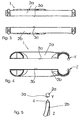
- Fig. 1 shows a perspective view of two correspondingly formed half-shells, 2a, 2b which are connected to produce a gas control system 1 along its longitudinal edges 3a, 3b with each other. All bends and branches of the gas control system 1 to be produced are already formed in the deep-drawn half shells 2 a, 2 b, so that no further production steps are required following the joining process of the half shells 2 a, 2 b (cf. Fig. 2-4 ).
- Ringbuckel 4 On the circumferential longitudinal edge 3b of the half-shell 2b a triangular in cross-section Ringbuckel 4 is arranged, which melts when connected by capacitor discharge welding and the two half-shells 2a, 2b cohesively connects to each other (see. Fig. 5 ).
- An embodiment of a method for producing the gas control system 1 comprises the following production steps:
- the half-shells 2a, 2b are produced from sheets having a thickness of 1 mm in the deep-drawing process according to the shape of the gas-conducting system 1 to be achieved.
- the half shells 2a, 2b are coated with a zinc layer in an electric bath.
- the half-shell 2b is provided along its longitudinal edges 3b with a triangular in cross section Ringbuckel 4.
- the half-shells 2a, 2b produced in this way are positioned in a welding installation, not shown here, so that they lie against one another along their longitudinal edges 3a, 3b.
- condenser discharge welding of the ring hump 4 melts and the half-shells 2a, 2b are materially connected to each other and form the gas control system.
Landscapes
- Engineering & Computer Science (AREA)
- Mechanical Engineering (AREA)
- Branch Pipes, Bends, And The Like (AREA)
- Lining Or Joining Of Plastics Or The Like (AREA)
- Rigid Pipes And Flexible Pipes (AREA)
- Non-Disconnectible Joints And Screw-Threaded Joints (AREA)
- Butt Welding And Welding Of Specific Article (AREA)
- Arc Welding In General (AREA)
Description
- Die Erfindung betrifft ein Verfahren zur Herstellung eines Leitungssystems zum Transport von fluiden Medien, wie z. B. Gasen und Flüssigkeiten nach dem Oberbegriffs des Anspruchs 1. Ein solches Verfahren ist aus der
EP 0 677 354 bekannt. - Zu den Leitungssystemen der eingangs genannten Art zählen im Sinne dieser Erfindung alle Anordnungen einschließlich Leitungen, Speichern, Verzweigungen oder Verteilern und dergleichen Einrichtungen, die sich für den Transport von fluiden Medien eignen oder hierfür eingesetzt werden. Es kann sich um einzelne Komponenten wie Rohrleitungsabschnitte, Verteiler oder Speicher handeln, die als Bestandteile von Leitungssystemen eingesetzt werden, es kann sich aber auch um einbaufertige Anordnungen der vorgenannten Komponenten handeln, die in einem Arbeitsgang zu einem Leitungssystem verbunden werden. Die Leitungssysteme umfassen bspw. Leitungssysteme oder deren Bestandteile für flüssige Medien, insbesondere Wasserleitungssysteme (Heizungen, Durchlauferhitzer, Getränkeleitungen), aber auch Gasleitsysteme, z. B. solche, die insbesondere in Fahrzeugen eingebaut werden, um in Falle eines Aufpralls des Fahrzeugs die mittlerweile an verschiedenen Stellen im Fahrzeug angeordneten Airbags aufzublasen, die den Aufprall der Fahrzeuginsassen auf Fahrzeugteile mindern oder verhindern sollen. Aber auch Gasleitungen von Gasspeichern oder anderen Gasquellen zu Heizquellen oder Kochstellen kommen hier in Frage.
- Den vorgenannten Leitungssystemen für fluide Medien ist gemeinsam, dass sie mediendicht sein müssen, also flüssigkeitsdicht und/oder gasdicht. Dabei werden bei Leitungssystemen, die drucklos betrieben werden oder die mit geringem Druck beaufschlagt werden, geringere Anforderungen an die Leitungssysteme gestellt. Leitungssysteme, die unter hohem Druck betrieben werden, müssen jedoch besonderen Anforderungen gerecht werden. Dies sei am Beispiel eines Airbag-Systems erläutert: Beim Aufprall wird das in einer den jeweiligen Airbags zugeordneten Gaspatrone gespeicherte Gas schlagartig freigesetzt und durch die entsprechenden Gasleitsysteme dem Airbag zugeleitet. Hier ist die Dichtigkeit des Systems nicht nur erforderlich, um das Funktionieren des Airbag-Systems zu gewährleisten. Ein Reißen des Leitungssystems als Folge mangelnder Dichtigkeit stellt zudem ein hohes Verletzungsrisiko für die Fahrzeuginsassen dar.
- Neben den seit bereits geraumer Zeit eingesetzten Fahrer- und Beifahrer-Airbags, für die aufgrund der Integrationsmöglichkeiten in das Lenkrad bzw. in das Armaturenbrett ein relativ großer Bauraum zur Verfügung steht, werden in zunehmender Weise Airbags, nämlich Window- Airbags, Side-Airbags, Kopf-Airbags etc. an solchen Stellen im Fahrzeug eingesetzt, an denen nur ein geringer Bauraum zur Integration der Airbags zur Verfügung steht.
- Der Einbau derartiger Airbags setzt deshalb in besonderer Weise die Verwendung von speziell geformten Leitungssystemen voraus. Diese lassen sich jedoch u.a. aufgrund der Mindestbiegeradien der für die Leitungssysteme verwendeten metallenen Rohrleitungen sowie aufgrund der zum Teil sehr komplexen Form nur mit einem sehr hohen technischen und finanziellen Aufwand fertigen, wobei die Leitungssysteme zum Teil aus zwei oder mehreren miteinander verbundenen Rohrleitungen hergestellt werden müssen, damit diese die gewünschte Form aufweisen.
- Ein gleiches Problem ergibt sich, wenn beispielsweise in Leitungssystemen für Flüssigkeiten Verteiler anzuordnen sind. Diese Verteiler müssen relativ ausladend konstruiert werden, da bisherige Herstellverfahren der Konstruktion enge Grenzen setzen, unter anderem dadurch, dass Mindest-Biegeradien einzuhalten sind.
- Aus der
DE 42 40 906 Metzeler Gimetall AG ist ein Verfahren bekannt, bei dem Rohrverzweigungen mittels Laserschweißung aus kaltverformten Blechteilen hergestellt werden. Nachteilig an diesem Verfahren ist, dass das Laserschweißen sehr aufwändig ist, und dass es sich um ein apparativ aufwändiges Verfahren mit sehr geringen Arbeitsgeschwindigkeiten handelt. Es ist zur wirtschaftlichen Herstellung von Serienprodukten nicht geeignet. Zudem können nur solche Schweißnähte gesetzt werden, die dem Laser zugänglich sind. Damit sind komplexe Leitungssysteme mit diesem Verfahren nicht herstellbar. - Der Erfindung liegt die Aufgabe zugrunde, ein Verfahren bereitzustellen, das die kostengünstige Herstellung von Leitungssystemen für fluide Medien ermöglicht.
- Die Erfindung löst die Aufgabe durch ein Verfahren gemäß Anspruch 1. Vorteilhafte Weiterbildungen der Erfindung sind in den abhängigen Ansprüchen beschrieben.
- Insbesondere das Kondensatorentladungsschweißen, bei dem mit einem Hochstromimpuls, der über eine transformierte Kondensatorentladung erzeugt wird, das Material im Kontaktbereich aufgeschmolzen wird, gewährleistet eine über die gesamte Erstreckung der Längsränder gleichmäßige und stabile Verbindung der Halbschalen. Dabei können auch mehrere Komponenten in einem einzigen Arbeitsgang zu dem Leitungssystem verbunden werden.
- Kondensatorentladungsschweißen ist an sich bekannt. Es wird zum Herstellen punktueller, im Einzelfall auch linienförmiger Verbindungen eingesetzt. Widerstandsschweißverfahren, vor allem auch das Kondensatorentladungsschweißen, wurden aber bisher nicht als geeignete Verfahren zum Herstellen gas- und/oder flüssigkeitsdichter Schweissverbindungen beurteilt. Überraschenderweise hat sich jedoch herausgestellt, dass Halbschalen aus Metall, die entlang ihrer Längsränder durch Widerstandsschweißen verbunden wurden, gas- und/oder flüssigkeitsdicht sind. Insbesondere mittels Kondensatorentladungsschweißen gefügte Halbschalen werden zu außerordentlich druckbeständigen Leitungssystemen verbunden. Im Rahmen zerstörender Werkstück-Prüfungen hat sich herausgestellt, dass Gas-Leitungssysteme, die nach dem erfindungsgemäßen Verfahren hergestellt wurden, einem Druck von bis zu 400 bar standgehalten haben, bevor das Leitungssystem zerstört wurde.
- Nach einer vorteilhaften Ausführung formen die verbundenen Halbschalen ein gas- und flüssigkeitsdichtes Leitungssystem. Im Falle der Verwendung als Gasleitsystem für Airbags leitet diese im Betriebszustand das gespeicherte Gas zu dem jeweiligen Airbag.
- Die Verwendung von Halbschalen, die bereits eine dem Leitungssystem, bspw. dem Heizungsleitsystem oder Gasleitsystem, entsprechende Kontur und den vorgegebenen Verlauf aufweisen, und die zudem bereits eventuell gewünschte Halterungen, Laschen, Ösen oder dergleichen aufweisen können, ermöglicht es, z.B. vollständig auf ein Biegen von Rohrleitungen des fertigen Leitungssystems zu verzichten. Somit können auch Leitungssysteme mit abgewinkelten Rohrleitungen gefertigt werden, deren Biegeradien kleiner sind als die durch den Rohrdurchmesser, mit Blick auf die Verarbeitung in Rohrbiegemaschinen, festgesetzten Mindestradien, die in der Regel dem 2 ½-fachen des Rohrdurchmessers entsprechen. Gleiches gilt für andere Bestandteile von Leitungssystemen, beispielsweise Verteiler oder Speicher, bei denen nach dieser bevorzugten Ausführungsform Halbschalen mit der jeweils gewünschten oder vorgeschriebenen Kontur miteinander verbunden werden.
- Insbesondere gegenüber der herkömmlichen Herstellung von Leitungssystemen, z.B. die aus mehreren einzelnen Rohrleitungsabschnitten gebildet werden, welche aufwändig gebogen, geschnitten, gebohrt und durch Schweißen, Verklemmen oder Verpressen miteinander verbunden werden müssen, zeichnet sich das erfindungsgemäße Verfahren dadurch aus, daß beim Vorliegen der entsprechend ausgebildeten Halbschalen ein einziger Herstellungsschritt ausreicht, um das Leitungssystem zu fertigen, womit gegenüber herkömmlichen Verfahren eine erhebliche Zeit- und Kostenreduzierung erzielt werden kann.
- Das erfindungsgemäße Verfahren zeichnet sich ferner dadurch aus, daß es sich besonders gut automatisieren lässt, wodurch die Pass- und Wiederholgenauigkeit in ergänzender Weise gesteigert werden kann. Zudem ermöglicht das Widerstandsschweißen eine besonders hohe Fertigungsgeschwindigkeit. So ist es beispielsweise unter Einsatz des Kondensatorentladungsschweiß-Verfahrens möglich, mittels einer Anlage ca. 1.000 Werkstücke pro Stunde herzustellen, also ca. 1.000 Schweißvorgänge innerhalb einer Stunde abzuwickeln.
- Die kurze Fertigungsdauer eröffnet einen weiteren Vorteil. Bedingt durch die extrem kurze Schweißzeit, die in der Regel nur wenige Millisekunden beträgt, wird die Energie nur auf die Schweißzone konzentriert, so daß nur ein sehr geringer Wärmeeintrag in das Material stattfindet. Die verschweißten Werkstücke können praktisch kalt aus einer Schweißanlage oder dergleichen entnommen werden und bleiben besonders formbeständig. Probleme mit der Passgenauigkeit durch Schweißverzug, wie er insbesondere bei herkömmlich hergestellten Leitungssystemen auftritt, werden somit wirksam vermieden.
- Zur ergänzenden Verbesserung der Formstabilität des herzustellenden Leitungssystems wird erfindungsgemäß vorgeschlagen, mindestens eine Halbschale zu verwenden, die entlang ihrer Längsränder mit einem Ringbuckel versehen ist, der beim Verbinden der Halbschalen aufschmilzt. Sofern der Ringbuckel nicht bereits bei der Herstellung der Halbschalen an den Längsrändern ausgebildet wurde, kann dieser in einem dem Verbinden vorangehenden Verfahrensschritt an den Längsrändern angeordnet werden.
- Die Verwendung eines Ringbuckels, der zur Verbindung der Halbschalen im wesentlichen vollständig aufschmilzt und das Verbindungsmittel bildet, gewährleistet eine optimale Formstabilität des Leitungssystems. Insbesondere kreisförmige Rohrleitungen lassen sich somit besonders einfach aus zwei im Querschnitt halbkreisförmigen Halbschalen herstellen. Ein andernfalls zu berücksichtigendes Einsinken von Teilbereichen der Halbschalen entlang der Längsränder tritt hierbei nicht auf.
- Ein weiterer Vorteil der Verwendung eines Ringbuckels, der grundsätzlich beliebig ausgebildet sein kann, vorzugsweise jedoch eine im Querschnitt halbrunde, ellipsoide oder eckige, insbesondere dreieckige Form aufweist, wodurch eine besonders zuverlässige Verbindung erreicht werden kann, besteht darin, daß dieser auch aus einem Material gebildet sein kann, das sich von dem Material für die Halbschalen unterscheidet. Die freie Materialwahl für das Verbindungsmittel ermöglicht es, die Zuverlässigkeit und Güte der Verbindung in ergänzender Weise zu verbessern.
- Falls es bei komplexen Leitungssystemen erforderlich ist, können Ringbuckel auch nur abschnittsweise, z. B. an besonders schwierig zu verbindenden Abschnitten oder an besonders dickwandigen Abschnitten oder Komponenten des Leitungssystems vorgesehen sein, während an anderen Abschnitten des Leitungssystems das Widerstandsschweißen ohne Ringbuckel erfolgt.
- Das erfindungsgemäße Verfahren kann sowohl zur Herstellung von Leitungssystemen mit besonders geringen Wandstärken, aber auch zur Herstellung von Leitungssystemen mit besonders großen Wandstärken eingesetzt werden. Die Wandstärken der Leitungssysteme können zwischen 0,5 mm und 5 mm liegen, wobei Wandstärken von 1 mm bis 1,5 mm besonders vielen Anwendungsfällen gerecht werden.
Grundsätzlich erlaubt das erfindungsgemäße Verfahren die Verwendung beliebig hergestellter, bspw. gießtechnisch oder frästechnisch hergestellter Halbschalen. Nach einer vorteilhaften Ausgestaltung der Erfindung werden jedoch Halbschalen verwendet, die durch Tiefziehen hergestellt sind. Sollten die Halbschalen nicht bereits in verwendbarer Form vorliegen, dann kann der Tiefziehprozess mit dem erfindungsgemäßen Verfahren kombiniert werden. Der Ausdruck Halbschalen bezieht sich sowohl auf Rohrabschnitte wie auf andere Bestandteile von Leitungssystemen, wie bereits vorstehend erläutert wurde. - Das Tiefziehen zeichnet sich insbesondere dadurch aus, daß damit auch sehr komplexe Formen besonders einfach hergestellt werden können. Das Tiefziehen erlaubt ferner die Verwendung von Blechen mit besonders niedrigen Dicken. Insbesondere können somit Leitungssysteme mit einer Wandstärke von 0,5 bis 1,5 mm, vorzugsweise 1 mm, hergestellt werden , die sich dadurch auszeichnen, daß sie besonders leicht sind und gleichzeitig die erforderliche Stabilität, insbesondere die erforderlichen Berstdrücke, wie sie bspw. bei Gasleitsystemen für Airbags gefordert werden, erreichen.
- Da für die Halbschalen grundsätzlich alle metallischen Werkstoffe verwendet werden können, kann das Leitungssystem optimal an den jeweiligen Einsatzzweck angepasst werden. Nach einer vorteilhaften Weiterbildung der Erfindung sind die das Leitungssystem bildenden Rohrleitungen aus verzinktem Vormaterial hergestellt oder werden in einem dem Verbinden der Halbschalen vorangehenden Verfahrensschritt verzinkt.
- Das Verzinken ist eine optimale Methode zum Schutz von Stahl. Hierbei wird das Produkt vorzugsweise nach einer speziellen Vorbehandlung entweder feuerverzinkt oder galvanisch verzinkt. Der so aufgebrachte Zinküberzug ist festhaftend, abrieb- und schlagfest. Durch seine hohe Beständigkeit gegen atmosphärische Beanspruchung schützt das Verzinken somit langfristig vor Korrosion.
- Der so hergestellte Korrosionsschutz, der auch durch den Verbindungsvorgang nicht zerstört wird, ermöglicht es, auf die nachträgliche Aufbringung eines gegebenenfalls geforderten Korrosionsschutzes zu verzichten, so daß die Herstellungskosten für das Leitungssystem in ergänzender Weise reduziert werden können.
- Das Leitungssystem oder dessen Komponente weist eine das Leitungssystem bildende Komponente auf, die aus zwei entlang ihrer Längsränder miteinander mittels Widerstandsschweißen, insbesondere Kondensatorentladungsschweißen verbundenen Halbschalen gebildet ist. Ein wesentlicher Vorteil dieser Leitungssysteme, zu denen bspw. Leitungen für Heizungen und Gasleitsysteme für Airbags zählen, besteht in den besonders geringen Herstellungskosten, die aus der Verwendung zweier Halbschalen resultiert, die jeweils bereits die dem Leitungssystem entsprechende Form aufweisen, so dass jede weitere Nachbearbeitung des Leitungssystems entfällt.
- Insbesondere die Herstellung komplexer Leitungssysteme, deren derzeitige Herstellung durch Biegen und teilweise umständliches Verbinden entsprechender Rohrleitungen erfolgt, kann wesentlich schneller und kostengünstiger erfolgen. Zudem bergen die erfindungsgemäßen Leitungssysteme aufgrund der geradlinigen Kontaktflächen, die problemlos zu verbinden sind, ein wesentlich geringeres Risiko für geschwächte Verbindungsstellen, so daß diese besonders zuverlässig sind. Außerdem können Leitungssysteme hergestellt werden, die besonders kompakt sind, da die Beschränkungen üblicher Biegeverfahren nicht mehr zu beachten sind. Schließlich können Leitungssysteme angeboten werden, bei denen komplexe Anordnungen aus Leitungsabschnitten, Verteilern, Speicherelementen und dergleichen durchgängig verbunden sind.
- Die erfindungsgemäß durch Widerstandsschweißen, insbesondere Kondensatorentladungsschweißen, miteinander verbundenen Halbschalen des Leitungssystems zeichnen sich durch ihren gleichmäßigen Verbindungsbereich aus, der eine besonders hohe Zuverlässigkeit des Leitungssystems gewährleistet. Die insbesondere beim Kondensatorentladungsschweißen entstehende geringe Wärmeeinflusszone verhindert dabei zuverlässig Gefügeänderungen im Material des Leitungssystems, die u.U. im Falle der Verwendung als Gasleitsystem für Airbags, zu einem Versagen des Systems im Betrieb führen könnten.
- Die zur Herstellung des Leitungssystems oder dessen Komponenten verwendeten Halbschalen können grundsätzlich beliebig hergestellt sein. Nach einer besonders vorteilhaften Ausführungsform der Erfindung sind die Halbschalen jedoch durch Tiefziehen hergestellt. Derartige Halbschalen zeichnen sich insbesondere durch ihre geringen Herstellungskosten aus, die es in ergänzender Weise ermöglichen, die Herstellungskosten des Leitungssystems zu senken. Zudem weisen die tiefgezogenen Halbschalen über ihre gesamte Erstreckung eine gleichmäßige Wandstärke auf.
- Nach einer weiteren Ausgestaltung der Erfindung werden verzinkte Halbschalen zur Herstellung der das Leitungssystem bildenden Komponenten verwendet. Dadurch kann auf einen separat aufzutragenden Korrosionsschutz verzichtet werden, wodurch die Herstellungskosten derartiger Leitungssysteme weiter reduziert werden können.
- Die Halbschalen werden nach einer Weiterbildung der Erfindung aus einem Blech mit einer Dicke von 0,5 bis 5 mm, vorzugsweise 1mm bis 1,5 mm hergestellt. Die unter Verwendung dieser Bleche hergestellten Leitungssysteme, insbesondere Gasleitsysteme, aber auch Flüssigkeitsleitsysteme zeichnen sich durch ihr geringes Gewicht aus, wobei gleichzeitig die an das Leitungssystem, insbesondere Gasleitsystem gestellten Stabilitätseigenschaften erfüllt werden.
- Nachstehend wird ein Ausführungsbeispiel der Erfindung anhand der Zeichnungen beschrieben. In den Zeichnungen zeigen:
- Fig. 1
- eine perspektivische Darstellung zweier zu einem Gasleitsystem eines Airbags zu verbindender Halbschalen;
- Fig. 2
- eine Draufsicht auf eine Halbschale von
Fig. 1 ; - Fig. 3
- eine Seitenansicht auf die Halbschalen von
Fig. 1 ; - Fig. 4
- eine Vorderansicht der Halbschalen von
Fig. 1 und - Fig. 5
- eine Vergrößerung der Ausschnitte Y und Z von
Fig. 4 . -
Fig. 1 zeigt eine perspektivische Ansicht zweier korrespondierend ausgebildeter Halbschalen, 2a, 2b die zu Herstellung eines Gasleitsystems 1 entlang ihrer Längsränder 3a, 3b miteinander verbunden werden. Sämtliche Biegungen und Abzweigungen des herzustellenden Gasleitsystems 1 sind bereits in den tiefgezogenen Halbschalen 2a, 2b ausgebildet, so daß im Anschluss an den Verbindungsvorgang der Halbschalen 2a, 2b keine weiteren Herstellungsschritte erforderlich sind (vgl.Fig. 2 - 4 ). - Auf dem umlaufenden Längsrand 3b der Halbschale 2b ist ein im Querschnitt dreieckiger Ringbuckel 4 angeordnet, der beim Verbinden durch Kondensatorentladungsschweißen aufschmilzt und die beiden Halbschalen 2a, 2b stoffschlüssig miteinander verbindet (vgl.
Fig. 5 ). - Eine Ausführungsform eines Verfahrens zur Herstellung des Gasleitsystems 1 umfasst folgende Herstellungsschritte:
- Zuerst werden die Halbschalen 2a, 2b aus Blechen mit einer Dicke von 1 mm im Tiefziehverfahren entsprechend der zu erreichenden Form des Gasleitsystems 1 hergestellt. In einem sich daran anschließenden Herstellungsschritt werden die Halbschalen 2a, 2b in einem elektrischen Bad mit einer Zinkschicht überzogen. Nachfolgend wird die Halbschale 2b entlang ihrer Längsränder 3b mit einem im Querschnitt dreieckigen Ringbuckel 4 versehen.
- Die so hergestellten Halbschalen 2a, 2b werden in einer hier nicht dargestellten Schweißanlage so positioniert, daß sie entlang ihrer Längsränder 3a, 3b aneinander liegen. Durch Kondensatorentladungsschweißen schmilzt der Ringbuckel 4 auf und die Halbschalen 2a, 2b werden stoffschlüssig miteinander verbunden und bilden das Gasleitsystem 1.
Claims (4)
- Verfahren zur Herstellung eines Leitungssystems zum Transport von fluiden Medien, wie Gasen und Flüssigkeiten oder von Komponenten hierfür, wobei das Leitungssystem mindestens eine Komponente aus Metall aufweist und die Komponente aus zwei Halbschalen (2a, 2b) gebildet wird, die entlang ihrer Längsränder (3a, 3b) durch Widerstandsschweißen, insbesondere Kondensatorentladungsschweißen miteinander verbunden werden, dadurch gekennzeichnet, daß mindestens eine Halbschale (2a, 2b) entlang ihrer Längsränder (3a, 3b) mindestens abschnittsweise mit einem Ringbuckel (4) versehen ist, der beim Verbinden der Halbschalen (2a, 2b) aufschmilzt.
- Verfahren nach Anspruch 1, dadurch gekennzeichnet, daß der Ringbuckel (4) eine im Querschnitt halbrunde, ellipsoide oder eckige, insbesondere dreieckige Form aufweist.
- Verfahren nach einem der vorhergehenden Ansprüche, dadurch gekennzeichnet, daß durch Tiefziehen hergestellte Halbschalen (2a, 2b) für die Herstellung eines Leitungssystems zum Transport von fluiden Medien verwendet werden.
- Verfahren nach einem der vorhergehenden Ansprüche, dadurch gekennzeichnet, daß die Halbschalen (2a, 2b) vor dem Verbinden verzinkt werden.
Priority Applications (1)
| Application Number | Priority Date | Filing Date | Title |
|---|---|---|---|
| PL05009453T PL1593558T3 (pl) | 2004-05-03 | 2005-04-29 | Zgrzewanie układów przewodów |
Applications Claiming Priority (4)
| Application Number | Priority Date | Filing Date | Title |
|---|---|---|---|
| DE200410022017 DE102004022017A1 (de) | 2004-05-03 | 2004-05-03 | Gasleitsystem |
| DE102004022017 | 2004-05-03 | ||
| DE102004057615A DE102004057615A1 (de) | 2004-05-03 | 2004-11-29 | Verfahren zum Schweißen von Leitungen |
| DE102004057615 | 2004-11-29 |
Publications (3)
| Publication Number | Publication Date |
|---|---|
| EP1593558A2 EP1593558A2 (de) | 2005-11-09 |
| EP1593558A3 EP1593558A3 (de) | 2006-11-29 |
| EP1593558B1 true EP1593558B1 (de) | 2011-12-07 |
Family
ID=34935960
Family Applications (1)
| Application Number | Title | Priority Date | Filing Date |
|---|---|---|---|
| EP05009453A Expired - Lifetime EP1593558B1 (de) | 2004-05-03 | 2005-04-29 | Schweißen von Leitungssystemen |
Country Status (4)
| Country | Link |
|---|---|
| EP (1) | EP1593558B1 (de) |
| AT (1) | ATE536285T1 (de) |
| DE (1) | DE102004057615A1 (de) |
| PL (1) | PL1593558T3 (de) |
Families Citing this family (7)
| Publication number | Priority date | Publication date | Assignee | Title |
|---|---|---|---|---|
| DE102006020000B3 (de) * | 2006-04-26 | 2007-11-08 | Thyssenkrupp Steel Ag | Verfahren zur Herstellung von rückfederungsarmen Halbschalen |
| WO2010048393A2 (en) * | 2008-10-22 | 2010-04-29 | Delphi Technologies, Inc. | Method for manufacturing a tubular frame structure |
| WO2010048381A2 (en) * | 2008-10-22 | 2010-04-29 | Delphi Technologies, Inc. | Improved method for manufacturing a tubular frame structure with stand alone node |
| DE102008059898A1 (de) * | 2008-12-02 | 2010-06-10 | Behr Gmbh & Co. Kg | Ejektor für einen Kältekreis und Herstellungsverfahren |
| DE102010019629A1 (de) | 2010-05-06 | 2011-11-10 | Zambelli Fertigungs Gmbh & Co. Kg | Dachentwässerungsteil aus mindestens einem Stahlblechzuschnitt und Herstellverfahren hierfür |
| CN102962651A (zh) * | 2012-12-14 | 2013-03-13 | 宝鸡市守善管件有限公司 | 大外径等径钛三通的制作方法 |
| WO2024040064A1 (en) * | 2022-08-19 | 2024-02-22 | Illinois Tool Works Inc. | Airbag diffuser |
Family Cites Families (4)
| Publication number | Priority date | Publication date | Assignee | Title |
|---|---|---|---|---|
| DE4333283A1 (de) * | 1992-09-26 | 1994-03-31 | Vaillant Joh Gmbh & Co | Schweißverfahren |
| DE4240906A1 (de) * | 1992-12-04 | 1994-06-09 | Metzeler Gimetall Ag | Verfahren zur Herstellung von rohrförmigen Bauteilen |
| DE4410178C2 (de) * | 1994-03-24 | 2000-03-23 | Benteler Werke Ag | Verfahren zur Herstellung von Hohlkörpern |
| IT1273142B (it) * | 1994-04-14 | 1997-07-04 | T D A Tecnologie D Automazione | Procedimento di fabbricazione, mediante saldatura a scarica capacitiva di elementi di radiatori termici di lamiera metallica per impianti di riscaldamento domestici ed elemento radiatore ottenuto con detto procedimento |
-
2004
- 2004-11-29 DE DE102004057615A patent/DE102004057615A1/de not_active Withdrawn
-
2005
- 2005-04-29 PL PL05009453T patent/PL1593558T3/pl unknown
- 2005-04-29 AT AT05009453T patent/ATE536285T1/de active
- 2005-04-29 EP EP05009453A patent/EP1593558B1/de not_active Expired - Lifetime
Also Published As
| Publication number | Publication date |
|---|---|
| PL1593558T3 (pl) | 2012-05-31 |
| EP1593558A3 (de) | 2006-11-29 |
| EP1593558A2 (de) | 2005-11-09 |
| ATE536285T1 (de) | 2011-12-15 |
| DE102004057615A1 (de) | 2006-06-01 |
Similar Documents
| Publication | Publication Date | Title |
|---|---|---|
| DE102007007810B4 (de) | Verfahren zum Formen einer komplex gestalteten Rohrstruktur | |
| EP1827727B1 (de) | Verfahren zur Herstellung eines Mehrlagenrohres | |
| WO2009056294A1 (de) | Strukturelement für einen fahrzeugsitz | |
| DE1966816A1 (de) | Rohr | |
| DE10022823A1 (de) | Verfahren zur Herstellung von Mehrschicht-Metall-Verbundrohren | |
| EP1593558B1 (de) | Schweißen von Leitungssystemen | |
| WO1998024569A1 (de) | Verfahren zur herstellung eines formteiles sowie nach diesem hergestelltes formteil | |
| DE102009013251B4 (de) | Kunststoff-Metall-Verbundrohr | |
| EP2822759B1 (de) | Leichtblech und eine leichtblech umfassende konstruktion | |
| EP0567667A1 (de) | Extrudiertes Kunststoff-Metall-Verbundrohr für Installationen | |
| DE102018116271A1 (de) | Verfahren zum Verbinden | |
| DE102005038472B4 (de) | Leitungsverbund zwischen einem Fitting und einem Verbundrohr sowie ein Verfahren zur Herstellung des Leitungsverbundes | |
| DE102004022017A1 (de) | Gasleitsystem | |
| DE19831047C2 (de) | Verfahren zur Herstellung von rohrartigen Strukturelementen und Strukturelement | |
| DE102016200357B4 (de) | Verfahren zum Fügen von mindestens zwei Bauteilen mittels eines gehärteten Fügeelements | |
| DE10210156A1 (de) | Verfahren zur Herstellung eines Rohres und Strukturkomponente, die aus einem solchen Rohr hergestellt ist | |
| DE102009012072B4 (de) | Anlage und Verfahren zum Herstellen eines Mehrschichtverbundrohres | |
| EP1876006B1 (de) | Vorrichtung zur Herstellung von Metallverbundrohren | |
| DE10326609B4 (de) | Hohlprofil und Verfahren zur Herstellung eines Hohlprofils | |
| EP1838569B1 (de) | Metallverstärkte hybridstruktur | |
| DE102005060486B4 (de) | Verfahren zur Herstellung eines hochbelastbaren Verbundteils sowie ein danach hergestelltes hochbelastbares Verbundteil und Verwendung | |
| DE102007010117A1 (de) | Strukturbauteil aus blechförmigem Material sowie Vorrichtung und Verfahren zum Fügen eines Strukturbauteils aus blechförmigem Material | |
| DE102016201638A1 (de) | Verfahren zum Herstellen eines Profils aus einem Sandwichmaterial, Profil aus einem Sandwichmaterial sowie dessen Verwendung | |
| DE102004008108A1 (de) | Überlappstoß zum Schweißen von beschichteten Werkstücken | |
| EP2095890B1 (de) | Verfahren zur Umformung eines Hohlprofilbauteils mittels Innenhochdruck |
Legal Events
| Date | Code | Title | Description |
|---|---|---|---|
| PUAI | Public reference made under article 153(3) epc to a published international application that has entered the european phase |
Free format text: ORIGINAL CODE: 0009012 |
|
| AK | Designated contracting states |
Kind code of ref document: A2 Designated state(s): AT BE BG CH CY CZ DE DK EE ES FI FR GB GR HU IE IS IT LI LT LU MC NL PL PT RO SE SI SK TR |
|
| AX | Request for extension of the european patent |
Extension state: AL BA HR LV MK YU |
|
| PUAL | Search report despatched |
Free format text: ORIGINAL CODE: 0009013 |
|
| AK | Designated contracting states |
Kind code of ref document: A3 Designated state(s): AT BE BG CH CY CZ DE DK EE ES FI FR GB GR HU IE IS IT LI LT LU MC NL PL PT RO SE SI SK TR |
|
| AX | Request for extension of the european patent |
Extension state: AL BA HR LV MK YU |
|
| RIC1 | Information provided on ipc code assigned before grant |
Ipc: B23K 11/26 20060101ALI20061023BHEP Ipc: B23K 11/16 20060101ALI20061023BHEP Ipc: B23K 101/14 20060101ALN20061023BHEP Ipc: B23K 33/00 20060101ALI20061023BHEP Ipc: B60R 21/26 20060101AFI20050831BHEP Ipc: B23K 11/14 20060101ALI20061023BHEP |
|
| RAP1 | Party data changed (applicant data changed or rights of an application transferred) |
Owner name: HUPERZ AUTOMOTIVE SYSTEMS GMBH & CO KG |
|
| 17P | Request for examination filed |
Effective date: 20070521 |
|
| AKX | Designation fees paid |
Designated state(s): AT BE BG CH CY CZ DE DK EE ES FI FR GB GR HU IE IS IT LI LT LU MC NL PL PT RO SE SI SK TR |
|
| 17Q | First examination report despatched |
Effective date: 20071123 |
|
| RAP1 | Party data changed (applicant data changed or rights of an application transferred) |
Owner name: PAMPUS AUTOMOTIVE GMBH & CO. KG |
|
| GRAP | Despatch of communication of intention to grant a patent |
Free format text: ORIGINAL CODE: EPIDOSNIGR1 |
|
| GRAS | Grant fee paid |
Free format text: ORIGINAL CODE: EPIDOSNIGR3 |
|
| GRAA | (expected) grant |
Free format text: ORIGINAL CODE: 0009210 |
|
| AK | Designated contracting states |
Kind code of ref document: B1 Designated state(s): AT BE BG CH CY CZ DE DK EE ES FI FR GB GR HU IE IS IT LI LT LU MC NL PL PT RO SE SI SK TR |
|
| REG | Reference to a national code |
Ref country code: GB Ref legal event code: FG4D Free format text: NOT ENGLISH |
|
| REG | Reference to a national code |
Ref country code: CH Ref legal event code: EP |
|
| REG | Reference to a national code |
Ref country code: IE Ref legal event code: FG4D Free format text: LANGUAGE OF EP DOCUMENT: GERMAN |
|
| REG | Reference to a national code |
Ref country code: RO Ref legal event code: EPE |
|
| REG | Reference to a national code |
Ref country code: DE Ref legal event code: R096 Ref document number: 502005012212 Country of ref document: DE Effective date: 20120308 |
|
| REG | Reference to a national code |
Ref country code: NL Ref legal event code: VDEP Effective date: 20111207 |
|
| PG25 | Lapsed in a contracting state [announced via postgrant information from national office to epo] |
Ref country code: LT Free format text: LAPSE BECAUSE OF FAILURE TO SUBMIT A TRANSLATION OF THE DESCRIPTION OR TO PAY THE FEE WITHIN THE PRESCRIBED TIME-LIMIT Effective date: 20111207 |
|
| LTIE | Lt: invalidation of european patent or patent extension |
Effective date: 20111207 |
|
| PG25 | Lapsed in a contracting state [announced via postgrant information from national office to epo] |
Ref country code: SE Free format text: LAPSE BECAUSE OF FAILURE TO SUBMIT A TRANSLATION OF THE DESCRIPTION OR TO PAY THE FEE WITHIN THE PRESCRIBED TIME-LIMIT Effective date: 20111207 Ref country code: SI Free format text: LAPSE BECAUSE OF FAILURE TO SUBMIT A TRANSLATION OF THE DESCRIPTION OR TO PAY THE FEE WITHIN THE PRESCRIBED TIME-LIMIT Effective date: 20111207 Ref country code: GR Free format text: LAPSE BECAUSE OF FAILURE TO SUBMIT A TRANSLATION OF THE DESCRIPTION OR TO PAY THE FEE WITHIN THE PRESCRIBED TIME-LIMIT Effective date: 20120308 Ref country code: NL Free format text: LAPSE BECAUSE OF FAILURE TO SUBMIT A TRANSLATION OF THE DESCRIPTION OR TO PAY THE FEE WITHIN THE PRESCRIBED TIME-LIMIT Effective date: 20111207 |
|
| REG | Reference to a national code |
Ref country code: PL Ref legal event code: T3 |
|
| PG25 | Lapsed in a contracting state [announced via postgrant information from national office to epo] |
Ref country code: CY Free format text: LAPSE BECAUSE OF FAILURE TO SUBMIT A TRANSLATION OF THE DESCRIPTION OR TO PAY THE FEE WITHIN THE PRESCRIBED TIME-LIMIT Effective date: 20111207 |
|
| REG | Reference to a national code |
Ref country code: IE Ref legal event code: FD4D |
|
| REG | Reference to a national code |
Ref country code: HU Ref legal event code: AG4A Ref document number: E013282 Country of ref document: HU |
|
| PG25 | Lapsed in a contracting state [announced via postgrant information from national office to epo] |
Ref country code: SK Free format text: LAPSE BECAUSE OF FAILURE TO SUBMIT A TRANSLATION OF THE DESCRIPTION OR TO PAY THE FEE WITHIN THE PRESCRIBED TIME-LIMIT Effective date: 20111207 Ref country code: IS Free format text: LAPSE BECAUSE OF FAILURE TO SUBMIT A TRANSLATION OF THE DESCRIPTION OR TO PAY THE FEE WITHIN THE PRESCRIBED TIME-LIMIT Effective date: 20120407 Ref country code: IE Free format text: LAPSE BECAUSE OF FAILURE TO SUBMIT A TRANSLATION OF THE DESCRIPTION OR TO PAY THE FEE WITHIN THE PRESCRIBED TIME-LIMIT Effective date: 20111207 Ref country code: EE Free format text: LAPSE BECAUSE OF FAILURE TO SUBMIT A TRANSLATION OF THE DESCRIPTION OR TO PAY THE FEE WITHIN THE PRESCRIBED TIME-LIMIT Effective date: 20111207 Ref country code: BG Free format text: LAPSE BECAUSE OF FAILURE TO SUBMIT A TRANSLATION OF THE DESCRIPTION OR TO PAY THE FEE WITHIN THE PRESCRIBED TIME-LIMIT Effective date: 20120307 Ref country code: CZ Free format text: LAPSE BECAUSE OF FAILURE TO SUBMIT A TRANSLATION OF THE DESCRIPTION OR TO PAY THE FEE WITHIN THE PRESCRIBED TIME-LIMIT Effective date: 20111207 |
|
| PG25 | Lapsed in a contracting state [announced via postgrant information from national office to epo] |
Ref country code: PT Free format text: LAPSE BECAUSE OF FAILURE TO SUBMIT A TRANSLATION OF THE DESCRIPTION OR TO PAY THE FEE WITHIN THE PRESCRIBED TIME-LIMIT Effective date: 20120409 |
|
| PLBE | No opposition filed within time limit |
Free format text: ORIGINAL CODE: 0009261 |
|
| STAA | Information on the status of an ep patent application or granted ep patent |
Free format text: STATUS: NO OPPOSITION FILED WITHIN TIME LIMIT |
|
| BERE | Be: lapsed |
Owner name: PAMPUS AUTOMOTIVE G.M.B.H. & CO. KG Effective date: 20120430 |
|
| PG25 | Lapsed in a contracting state [announced via postgrant information from national office to epo] |
Ref country code: DK Free format text: LAPSE BECAUSE OF FAILURE TO SUBMIT A TRANSLATION OF THE DESCRIPTION OR TO PAY THE FEE WITHIN THE PRESCRIBED TIME-LIMIT Effective date: 20111207 |
|
| 26N | No opposition filed |
Effective date: 20120910 |
|
| PG25 | Lapsed in a contracting state [announced via postgrant information from national office to epo] |
Ref country code: IT Free format text: LAPSE BECAUSE OF FAILURE TO SUBMIT A TRANSLATION OF THE DESCRIPTION OR TO PAY THE FEE WITHIN THE PRESCRIBED TIME-LIMIT Effective date: 20111207 Ref country code: MC Free format text: LAPSE BECAUSE OF NON-PAYMENT OF DUE FEES Effective date: 20120430 |
|
| REG | Reference to a national code |
Ref country code: CH Ref legal event code: PL |
|
| GBPC | Gb: european patent ceased through non-payment of renewal fee |
Effective date: 20120429 |
|
| REG | Reference to a national code |
Ref country code: DE Ref legal event code: R097 Ref document number: 502005012212 Country of ref document: DE Effective date: 20120910 |
|
| REG | Reference to a national code |
Ref country code: FR Ref legal event code: ST Effective date: 20121228 |
|
| PG25 | Lapsed in a contracting state [announced via postgrant information from national office to epo] |
Ref country code: GB Free format text: LAPSE BECAUSE OF NON-PAYMENT OF DUE FEES Effective date: 20120429 Ref country code: BE Free format text: LAPSE BECAUSE OF NON-PAYMENT OF DUE FEES Effective date: 20120430 Ref country code: CH Free format text: LAPSE BECAUSE OF NON-PAYMENT OF DUE FEES Effective date: 20120430 Ref country code: LI Free format text: LAPSE BECAUSE OF NON-PAYMENT OF DUE FEES Effective date: 20120430 |
|
| PG25 | Lapsed in a contracting state [announced via postgrant information from national office to epo] |
Ref country code: FR Free format text: LAPSE BECAUSE OF NON-PAYMENT OF DUE FEES Effective date: 20120430 |
|
| PG25 | Lapsed in a contracting state [announced via postgrant information from national office to epo] |
Ref country code: ES Free format text: LAPSE BECAUSE OF FAILURE TO SUBMIT A TRANSLATION OF THE DESCRIPTION OR TO PAY THE FEE WITHIN THE PRESCRIBED TIME-LIMIT Effective date: 20120318 |
|
| REG | Reference to a national code |
Ref country code: AT Ref legal event code: MM01 Ref document number: 536285 Country of ref document: AT Kind code of ref document: T Effective date: 20120429 |
|
| PG25 | Lapsed in a contracting state [announced via postgrant information from national office to epo] |
Ref country code: FI Free format text: LAPSE BECAUSE OF FAILURE TO SUBMIT A TRANSLATION OF THE DESCRIPTION OR TO PAY THE FEE WITHIN THE PRESCRIBED TIME-LIMIT Effective date: 20111207 |
|
| PG25 | Lapsed in a contracting state [announced via postgrant information from national office to epo] |
Ref country code: AT Free format text: LAPSE BECAUSE OF NON-PAYMENT OF DUE FEES Effective date: 20120429 |
|
| PGFP | Annual fee paid to national office [announced via postgrant information from national office to epo] |
Ref country code: HU Payment date: 20130423 Year of fee payment: 9 Ref country code: RO Payment date: 20130419 Year of fee payment: 9 Ref country code: PL Payment date: 20130410 Year of fee payment: 9 |
|
| PG25 | Lapsed in a contracting state [announced via postgrant information from national office to epo] |
Ref country code: TR Free format text: LAPSE BECAUSE OF FAILURE TO SUBMIT A TRANSLATION OF THE DESCRIPTION OR TO PAY THE FEE WITHIN THE PRESCRIBED TIME-LIMIT Effective date: 20111207 |
|
| PG25 | Lapsed in a contracting state [announced via postgrant information from national office to epo] |
Ref country code: LU Free format text: LAPSE BECAUSE OF NON-PAYMENT OF DUE FEES Effective date: 20120429 |
|
| REG | Reference to a national code |
Ref country code: DE Ref legal event code: R082 Ref document number: 502005012212 Country of ref document: DE Representative=s name: KALKOFF & PARTNER PATENTANWAELTE, DE |
|
| REG | Reference to a national code |
Ref country code: DE Ref legal event code: R082 Ref document number: 502005012212 Country of ref document: DE Representative=s name: KALKOFF & PARTNER PATENTANWAELTE, DE Effective date: 20140620 Ref country code: DE Ref legal event code: R081 Ref document number: 502005012212 Country of ref document: DE Owner name: AUTOLIV DEVELOPMENT AB, SE Free format text: FORMER OWNER: ULRICH HUPERZ SCHWEISSTECHNIK GMBH & CO.KG, 57439 ATTENDORN, DE Effective date: 20120112 Ref country code: DE Ref legal event code: R081 Ref document number: 502005012212 Country of ref document: DE Owner name: AUTOLIV DEVELOPMENT AB, SE Free format text: FORMER OWNER: PAMPUS AUTOMOTIVE GMBH & CO. KG, 58540 MEINERZHAGEN, DE Effective date: 20140620 |
|
| PG25 | Lapsed in a contracting state [announced via postgrant information from national office to epo] |
Ref country code: RO Free format text: LAPSE BECAUSE OF NON-PAYMENT OF DUE FEES Effective date: 20140429 |
|
| PG25 | Lapsed in a contracting state [announced via postgrant information from national office to epo] |
Ref country code: HU Free format text: LAPSE BECAUSE OF NON-PAYMENT OF DUE FEES Effective date: 20140430 |
|
| REG | Reference to a national code |
Ref country code: PL Ref legal event code: LAPE |
|
| PG25 | Lapsed in a contracting state [announced via postgrant information from national office to epo] |
Ref country code: PL Free format text: LAPSE BECAUSE OF NON-PAYMENT OF DUE FEES Effective date: 20140429 |
|
| PGFP | Annual fee paid to national office [announced via postgrant information from national office to epo] |
Ref country code: DE Payment date: 20170426 Year of fee payment: 13 |
|
| REG | Reference to a national code |
Ref country code: DE Ref legal event code: R119 Ref document number: 502005012212 Country of ref document: DE |
|
| PG25 | Lapsed in a contracting state [announced via postgrant information from national office to epo] |
Ref country code: DE Free format text: LAPSE BECAUSE OF NON-PAYMENT OF DUE FEES Effective date: 20181101 |