EP1593533A2 - Automatic device for mounting and dismounting tires - Google Patents
Automatic device for mounting and dismounting tires Download PDFInfo
- Publication number
- EP1593533A2 EP1593533A2 EP05075974A EP05075974A EP1593533A2 EP 1593533 A2 EP1593533 A2 EP 1593533A2 EP 05075974 A EP05075974 A EP 05075974A EP 05075974 A EP05075974 A EP 05075974A EP 1593533 A2 EP1593533 A2 EP 1593533A2
- Authority
- EP
- European Patent Office
- Prior art keywords
- tire
- dismounting
- rim
- toothed wheel
- articulated
- Prior art date
- Legal status (The legal status is an assumption and is not a legal conclusion. Google has not performed a legal analysis and makes no representation as to the accuracy of the status listed.)
- Granted
Links
Images


Classifications
-
- B—PERFORMING OPERATIONS; TRANSPORTING
- B60—VEHICLES IN GENERAL
- B60C—VEHICLE TYRES; TYRE INFLATION; TYRE CHANGING; CONNECTING VALVES TO INFLATABLE ELASTIC BODIES IN GENERAL; DEVICES OR ARRANGEMENTS RELATED TO TYRES
- B60C25/00—Apparatus or tools adapted for mounting, removing or inspecting tyres
- B60C25/01—Apparatus or tools adapted for mounting, removing or inspecting tyres for removing tyres from or mounting tyres on wheels
- B60C25/05—Machines
- B60C25/132—Machines for removing and mounting tyres
- B60C25/135—Machines for removing and mounting tyres having a tyre support or a tool, movable along wheel axis
- B60C25/138—Machines for removing and mounting tyres having a tyre support or a tool, movable along wheel axis with rotary motion of tool or tyre support
-
- B—PERFORMING OPERATIONS; TRANSPORTING
- B60—VEHICLES IN GENERAL
- B60C—VEHICLE TYRES; TYRE INFLATION; TYRE CHANGING; CONNECTING VALVES TO INFLATABLE ELASTIC BODIES IN GENERAL; DEVICES OR ARRANGEMENTS RELATED TO TYRES
- B60C25/00—Apparatus or tools adapted for mounting, removing or inspecting tyres
- B60C25/01—Apparatus or tools adapted for mounting, removing or inspecting tyres for removing tyres from or mounting tyres on wheels
- B60C25/05—Machines
- B60C25/0563—Tools interacting with the tyre and moved in relation to the tyre during operation
- B60C25/0578—Tools interacting with the tyre and moved in relation to the tyre during operation hooking only
Definitions
- the present invention refers to an automatic device for mounting and dismounting tires in accordance with the preamble of claim 1.
- the present invention refers to an automatic device for mounting and dismounting tires installed on tire-dismounting machines, which allow the tire to be mounted and or dismounted on a rim of a wheel for automobiles.
- machines that comprise a rotating platform with a vertical axis equipped with a self-centring device for locking the rim, this rim having a support positioned over it that supports a tire-dismounting tool, which can be adjusted both in height and in the horizontal direction, suitable for cooperating with the edge, or bead, of the tire to push it below the edge of the rim and then withdraw it.
- said tool is arranged at the end of a vertical support stem that slides in an end seat of a horizontal arm with respect to which it can be locked in level.
- the horizontal arm is in turn free to slide in the end seat of a vertical post that rises from the base of the machine at the side of the platform that receives the tire.
- Such an arm is equipped with means suitable for locking the tire-dismounting tool in the desired position.
- the dismounting operation of a tire from the rim foresees the prior detachment of the bead of the tire from the bead-locking edge of the rim by means of a suitable device called a bead breaker, which can be separate from the tire-dismounting machine.
- the wheel complete with rim and tire is arranged on the self-centring device and locked.
- the dismounting tool is moved closer to the edge of the rim where it is inserted under the bead of the tire and lifts it above the edge of the rim itself.
- This dismounting operation requires the active intervention of a trained operator.
- the dismounting tool is associated with an operating head that is positionable in level and horizontally translatable, which can take up a first configuration for seeking and gripping the bead of the tire, and a second configuration for extracting the bead of the tire from the rim.
- the support means on which the rim is locked translate in a direction perpendicular to the axis to position the edge of the rim in the operating range of the tool.
- the device must work automatically, be simple and quick to use even for a user without particular expertise, have little constructive difficulty and be able to be used with tire-dismounting machines of the prior art.
- the purpose of the present invention is that of providing an automatic device for mounting and dismounting tires having structural and functional characteristics such as to satisfy the aforementioned requirements and at the same time to avoid the aforementioned drawbacks with reference to the prior art, in the context of a simple and rational constructive solution.
- an automatic device for mounting and dismounting tires in accordance with the present invention is globally indicated with 1.
- Said device can be associated with a tire-dismounting machine 100.
- Said machines 100 are of the conventional type and therefore shall not be described with particular detail hereafter.
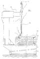
- the machine 100 briefly comprises a lower base 101 on which are associated support and locking means 102 of the rim 201 of a wheel 200 with tire 202.
- the support and locking means 102 are suitable for rotating about a vertical rotation axis Z-Z through the actuation of suitable motor means, generally arranged inside the lower base 101, per se known and not illustrated.
- a vertical post 103 integrally associated with the edge of the base 101, rises from the base 101.
- a support arm 104 extending horizontally and locked at the upper end, is associated with said post 103.
- Said arm 104 is free to slide horizontally.
- the device 1 of the present invention is associated with said support arm 104 at the end that is distal from the post 103.
- the device 1 comprises a pipe extending vertically along an axis X-X substantially parallel to the rotation axis Z-Z and associated with the support arm 104.
- a mobile shaft 2b is slidably inserted between a position away from the rim and a position close to the rim 201, when the latter is fixed to the support and locking means 102.
- the mobile shaft 2b is prism-shaped suitable for preventing it from rotating about the axis X-X.
- the mobile shaft 2b is commanded by means not illustrated in the figures.
- An articulated system 3 comprising a dismounting tool 4 is associated with the lower free end of the mobile shaft 2b.
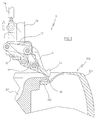
- Said articulated system 3 is actuated by a cylinder-piston group 5 that causes a roto-translation of the dismounting tool 4 between a first configuration for seeking and gripping the bead of the tire 202 (figs. 3, 4 and 5) and a second configuration for extracting said bead 202' from the rim 201 (fig. 7).
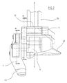
- said articulated system 3 comprises an articulated quadrilateral made up of the tool 4, the connecting rods 13 and 14 and the body 6 to which the connecting rods 13, 14 are articulated in turn fixed to the lower free end of the mobile shaft 2b, and a manoeuvring lever 7, the function of which shall become clearer later on in the description.
- the cylinder-piston group 5 is arranged next to the pipe/mobile shaft group 2, 2b and extends substantially parallel to it.
- Said cylinder-piston group 5 cooperates with the articulated quadrilateral through a gear comprising a first toothed wheel sector 8 and a second toothed wheel sector 9 that intermesh, respectively integral with the lever 7 and the connecting rod 13.
- the manoeuvring lever 7 has a first end 7' hinged through a first articulation pin 10 to the lower end of the stem 5a of the cylinder-piston group 5 and a second end 7" fitted on a first rotation shaft 11.
- the first rotation shaft 11 is arranged perpendicular to the manoeuvring lever 7 with rotation axis parallel to the rotation axis about the first pin 10 and is inserted, free to rotate in a seat formed in a bushing 12 fixed to the body 6 arranged at the lower end of the mobile shaft 2b.
- the first shaft 11 carries the first toothed wheel sector 8 at the opposite end to the one where the manoeuvring lever 7 is fitted.
- the manoeuvring lever 7 is fitted on one side of the bushing 12 and on the other side of the bushing 12 the first toothed wheel sector 8 is fitted.
- the first toothed wheel sector 8 meshes with the second toothed wheel sector 9.
- the connecting rod 13 and the connecting rod 14 are respectively fitted on a second rotation shaft 15 and a third rotation shaft.
- Said second and third shaft 15, 16 are arranged parallel to the first shaft 11 and are inserted, free to rotate, in two seats formed in the body 6 that comprises a bead-guide 20, the function of which shall be described later on, associated with the bushing 12 and able to be made in a single piece with it.
- the dismounting tool 4 constitutes one of the sides of the articulated quadrilateral and has an appendix 4a forming an angle slightly greater than 90° with the longitudinal axis of the connecting rod itself.
- the appendix 4a of the tool 4 is shaped like a hook in order to allow the bead 202' of the tire 202 that is to be dismounted to be hooked.
- the articulated quadrilateral and the first and second toothed wheel sector 8, 9 lie substantially on a common plane parallel to the plane on which the manoeuvring lever 7 lies, as can be seen in the figures.
- the bead-guide 20 has the function of easing the positioning of the dismounting tool 4 at the bead 202' of the tire 202 that is to be dismounted, as well as, in virtue of its particular configuration (see fig. 2), of easing the mounting operation of the tire 202 on the rim 201.
- the wheel 200 is positioned on the support and locking means 102 that allow the rim 201 to be firmly locked and, if actuated by the motor means, allow the wheel 200 to be rotated about the axis Z-Z.
- the pipe 2 with the inner mobile shaft 2b is arranged a distance from the post 103 such as to manage to take the tire-dismounting tool 4 onto the vertical of the edge of the rim 201.
- the mobile shaft 2b is made to slide vertically towards the edge of the rim 201 and is locked when the bead-guide 20 licks the edge of the rim 201 without touching it, to avoid possible damage, even of the elastic type.
- the stem 5a causes the oscillation of the manoeuvring lever 7 about the axis of the first shaft 11.
- the rotation of the second toothed wheel sector 9 in turn causes the rotation of the connecting rod 13 integrally associated with it and the consequent deformation of the articulated quadrilateral that transmits the roto-translating motion to the tire-dismounting tool 4, 4a that goes from the seeking configuration (figs. 3, 4) to the extraction configuration (fig. 7) after having gripped the bead 202' of the tire 202.
- the hooked appendix 4a of the tool 4 is preferably positioned, together with the bead gripped to it 202', inside the most outer circumference that envelops the rim 201.
- the support and locking means 102 are actuated as known in the field.
- the automatic device for mounting and dismounting tires according to the present invention allows the requirements to be satisfied and the drawbacks mentioned in the introductory part of the present description with reference to the prior art to be overcome.
- the automatic device for mounting and dismounting tires of the present invention is extremely simple to use as well as effective in the operations carried out, managing to carry out all of the necessary operations for the mounting/dismounting of tires, reducing the actions of the operator to a minimum.
- said automatic device for mounting and dismounting tires can also be applied to conventional tire-dismounting machines without the need for large modifications.
Landscapes
- Engineering & Computer Science (AREA)
- Mechanical Engineering (AREA)
- Automatic Assembly (AREA)
- Tires In General (AREA)
- Tyre Moulding (AREA)
- Vehicle Cleaning, Maintenance, Repair, Refitting, And Outriggers (AREA)
- Automobile Manufacture Line, Endless Track Vehicle, Trailer (AREA)
Abstract
Description
- figure 1 shows a side view of an automatic device for mounting and dismounting tires in accordance with the present invention, installed on a tire-dismounting machine;
- figure 2 shows a front view of a detail of the device of figure 1;
- figures 3 and 4 show a section view of figure 2, respectively taken along the plane III-III and IV-IV of figure 2, in the position for seeking the bead of the tire;
- figures 5, 6 and 7 show, in succession, section views of the device of the present invention during the dismounting of a tire.
Claims (10)
- Automatic device (1) for mounting and dismounting a tire (100) onto/from the rim (201) of a wheel (120) associated with a tire-dismounting machine (100) comprising a lower base (101) on which are associated rotating support and locking means (102) of the rim (201) of a wheel, a pole (103) extending vertically associated with said base (101), a horizontal support arm (104) associated with said pole (103), characterised in that it comprises a mobile shaft (2b) that can slide vertically inside a pipe (2) supported so that it can slide horizontally on said arm (104), an articulated system (3) comprising an articulated quadrilateral made up of a tire-dismounting tool (4), a pair of opposite connecting rods (13, 14) and a body (6) to which said connecting rods (13, 14) are articulated, said body (6) being fixed to the lower end of the mobile shaft (2b), and a manoeuvring lever (7) articulated with said quadrilateral and suitable for deforming it to transmit the roto-translating motion to the tool (4) that goes from a seeking configuration to an extraction configuration of the bead (202') from the rim (201).
- Device (1) according to claim 1, wherein said manoeuvring lever (7) cooperates in abutment with said articulated quadrilateral through a gear comprising a first toothed wheel sector (8) and a second toothed wheel sector (9) intermeshed with each other.
- Device (1) according to claim 2, wherein said manoeuvring lever (7) is commanded by a cylinder-piston group (5).
- Device (1) according to claim 3, wherein said manoeuvring lever (7) has a first end (7') hinged through a first articulation pin (10) to the end of the stem (5a) of said cylinder-piston group (5) and a second end (7") fitted onto a first rotation shaft (11).
- Device (1) according to claim 4, wherein said first toothed wheel sector (8) is fitted onto said first rotation shaft (11).
- Device (1) according to claim 2, wherein said connecting rods (13, 14) are respectively fitted onto a second rotation shaft (15) and a third rotation shaft (16).
- Device (1) according to claim 6, wherein said second toothed wheel sector (9) is fitted onto said second rotation shaft (15).
- Device (1) according to claim 2, wherein said articulated quadrilateral and said first toothed wheel sector (8) and second toothed wheel sector (9) lie substantially on the same plane, said plane being parallel to the plane on which said manoeuvring lever (7) lies.
- Device (1) according to claim 1, wherein said tool (4) has a hook-shaped appendix (4a).
- Device (1) according to claim 1, wherein said body (6) comprises a bead-guide (20).
Applications Claiming Priority (2)
| Application Number | Priority Date | Filing Date | Title |
|---|---|---|---|
| ITRE20040049 | 2004-05-06 | ||
| IT000049A ITRE20040049A1 (en) | 2004-05-06 | 2004-05-06 | AUTOMATIC DEVICE FOR DISASSEMBLY AND ASSEMBLY OF TIRES |
Publications (3)
| Publication Number | Publication Date |
|---|---|
| EP1593533A2 true EP1593533A2 (en) | 2005-11-09 |
| EP1593533A3 EP1593533A3 (en) | 2006-11-08 |
| EP1593533B1 EP1593533B1 (en) | 2008-03-05 |
Family
ID=34938213
Family Applications (1)
| Application Number | Title | Priority Date | Filing Date |
|---|---|---|---|
| EP05075974A Expired - Lifetime EP1593533B1 (en) | 2004-05-06 | 2005-04-25 | Automatic device for mounting and dismounting tires |
Country Status (7)
| Country | Link |
|---|---|
| US (1) | US7128119B2 (en) |
| EP (1) | EP1593533B1 (en) |
| JP (1) | JP5069845B2 (en) |
| CN (1) | CN100457480C (en) |
| DE (1) | DE602005005103T2 (en) |
| ES (1) | ES2302119T3 (en) |
| IT (1) | ITRE20040049A1 (en) |
Cited By (15)
| Publication number | Priority date | Publication date | Assignee | Title |
|---|---|---|---|---|
| EP1714807A1 (en) * | 2005-03-23 | 2006-10-25 | BUTLER ENGINEERING & MARKETING SPA | Tool for automatically assembling or disassembling a tyre to/from a wheel rim |
| EP1743782A1 (en) * | 2005-07-11 | 2007-01-17 | CORGHI S.p.A. | Method and device for dismounting run-flat tyres |
| EP1944177A1 (en) * | 2007-01-15 | 2008-07-16 | Snap-on Equipment Srl a unico socio. | Device for mounting or dismounting a pneumatic tyre from the rim of a vehicle wheel |
| EP2110270A1 (en) * | 2008-04-17 | 2009-10-21 | Snap-on Equipment Srl a unico socio. | Method of and apparatus for fitting or removing a motor vehicle tyre |
| ITBO20080540A1 (en) * | 2008-09-08 | 2010-03-09 | M & B Engineering S R L | TIRE ASSEMBLY AND DISASSEMBLY |
| ITMO20080265A1 (en) * | 2008-10-13 | 2010-04-14 | Giuliano Spa | OPERATING HEAD FOR DISASSEMBLY AND ASSEMBLY OF WHEEL TIRES FOR VEHICLES |
| ITMO20090078A1 (en) * | 2009-03-27 | 2010-09-28 | Sicam Srl | MACHINE FOR ASSEMBLY AND DISASSEMBLY OF WHEEL TIRES FOR VEHICLES |
| EP2298580A1 (en) | 2009-09-21 | 2011-03-23 | du Quesne, Bertrand | Machine for installing and removing tyres |
| EP2463125A1 (en) | 2010-12-09 | 2012-06-13 | Butler Engineering & Marketing S.p.A. | A device for demounting a tire from a rim as well as a tire demounting machine equipped with such device. |
| EP2524821A1 (en) | 2011-05-20 | 2012-11-21 | Butler Engineering & Marketing S.p.A. | Device for the automatic demounting of a tire from a rim and machine equipped with such device |
| ITMO20120009A1 (en) * | 2012-01-16 | 2013-07-17 | Gino Ferrari | EXTRACTOR DEVICE FOR REMOVAL MACHINES |
| EP2650147A1 (en) | 2012-04-11 | 2013-10-16 | CORGHI S.p.A. | A tyre removal tool for a tyre removing machine and a tyre removing machine |
| ITMO20130138A1 (en) * | 2013-05-20 | 2014-11-21 | Gino Ferrari | UNIVERSAL DEVICE FOR REMOVAL TIRE MACHINES |
| IT201900019864A1 (en) | 2019-10-28 | 2021-04-28 | Beissbarth Gmbh | TIRE CHANGING MACHINE |
| EP4011652A1 (en) | 2020-12-10 | 2022-06-15 | NEXION S.p.A. | Working head for a tyre changing apparatus |
Families Citing this family (21)
| Publication number | Priority date | Publication date | Assignee | Title |
|---|---|---|---|---|
| ITMO20060244A1 (en) * | 2006-07-28 | 2008-01-29 | Gino Ferrari | ACTUATOR GROUP |
| ITMO20070350A1 (en) * | 2007-11-21 | 2009-05-22 | Giuliano Spa | MACHINE FOR ASSEMBLY AND DISASSEMBLY OF WHEEL TIRES FOR VEHICLES |
| US8307874B1 (en) | 2008-01-25 | 2012-11-13 | Hunter Engineering Company | Tire changing method and machine with angularly positionable drive axis |
| JP5026473B2 (en) * | 2009-06-30 | 2012-09-12 | 小野谷機工株式会社 | How to remove the bead on the tire |
| JP5026477B2 (en) * | 2009-07-30 | 2012-09-12 | 小野谷機工株式会社 | Method and apparatus for removing tire bead |
| US8973640B1 (en) | 2010-12-07 | 2015-03-10 | Hunter Engineering Company | Demount tool assembly and methods for automated tire changer machine |
| IT1403494B1 (en) * | 2010-12-23 | 2013-10-17 | Butler Eng & Marketing | DISASSEMBLY DEVICE OF THE SECOND HEEL OF A TIRE FROM A RIM AND ITS RELATION METHOD |
| ITMO20110119A1 (en) * | 2011-05-20 | 2012-11-21 | Giuliano Group Spa | MACHINE FOR ASSEMBLY AND DISASSEMBLY OF WHEEL TIRES FOR VEHICLES |
| ITMO20110316A1 (en) * | 2011-12-02 | 2013-06-03 | Giuliano Group Spa | OPERATING HEAD FOR DISASSEMBLY AND ASSEMBLY OF WHEEL TIRES FOR VEHICLES |
| ITVR20120159A1 (en) * | 2012-08-01 | 2014-02-02 | Butler Engineering And Marketing S P A | DISMANTLING DEVICE OF A TIRE FROM A RIM AND METHOD OF DISASSEMBLY OF A WHEELED WHEEL |
| CA2944344C (en) | 2014-04-03 | 2019-04-16 | Bridgestone Bandag, Llc | Automatic system and method for mounting and dismounting tire casing on expandable rim hub in retreading operations |
| EP3501862B1 (en) * | 2014-05-30 | 2022-08-03 | Snap-on Equipment Srl a unico socio | Method for mounting and demounting a tyre to and from a wheel rim |
| EP2987661B1 (en) * | 2014-07-28 | 2019-10-23 | Butler Engineering & Marketing S.p.A. | Device for assembling-disassembling a tyred wheel, as well as machine comprising such a device |
| DE202014008932U1 (en) * | 2014-11-11 | 2016-03-02 | Snap-On Equipment Srl A Unico Socio | Tire mounting and dismounting tool |
| KR20180084962A (en) | 2015-12-24 | 2018-07-25 | 미츠비시 쥬고 기카이 시스템 가부시키가이샤 | Master disk, how to attach and detach it |
| TWI605242B (en) * | 2015-12-24 | 2017-11-11 | Mitsubishi Heavy Industries Machinery Tech Corporation | Master disk and its mounting method and removing method |
| CN105459743A (en) * | 2015-12-25 | 2016-04-06 | 镇江奥兰迪汽车部件有限公司 | Tire installing tool for hub |
| EP3315331B1 (en) * | 2016-10-18 | 2019-04-03 | NEXION S.p.A. | Tyre changing machine |
| CN107655679A (en) * | 2017-11-06 | 2018-02-02 | 苏州展德自动化设备有限公司 | Car seat motor loading test device |
| CN108944283A (en) * | 2018-08-02 | 2018-12-07 | 郑州精通汽车零部件有限公司 | One kind is blown out emergency safety device installation tool and its application method |
| CN110303831B (en) * | 2019-06-25 | 2021-07-20 | 北京恒通汇新能源汽车科技有限公司 | High-efficiency tire changer |
Family Cites Families (7)
| Publication number | Priority date | Publication date | Assignee | Title |
|---|---|---|---|---|
| DE3334203A1 (en) * | 1983-09-22 | 1985-04-18 | Continental Gummi-Werke Ag, 3000 Hannover | AIR TIRE ASSEMBLY DEVICE |
| IT1249760B (en) * | 1991-05-03 | 1995-03-17 | Sicesp Elettromeccaniche | HIGH-FLEXIBILITY USE BREASTER GROUP. |
| IT1310590B1 (en) * | 1999-05-14 | 2002-02-19 | Giuliano Srl | MULTIFUNCTIONAL STATION FOR THE ASSEMBLY AND DISASSEMBLY OF DIPNEUMATICS BOTH CONVENTIONAL AND SPECIAL. |
| IT1319475B1 (en) * | 2000-08-03 | 2003-10-10 | Corghi Spa | AUTOMATIC DEVICE FOR DISASSEMBLY AND ASSEMBLY OF PNEUMATICS, AND TIRE CHANGER MACHINES SO EQUIPPED |
| JP3626088B2 (en) * | 2000-11-09 | 2005-03-02 | 小野谷機工株式会社 | Automobile tire removing method and tire removing device |
| ITRE20020068A1 (en) * | 2002-09-13 | 2004-03-14 | Corghi Spa | AUTOMATIC SIMPLIFIED DEVICE FOR DISASSEMBLY |
| ITMO20030132A1 (en) * | 2003-05-09 | 2004-11-10 | Giuliano Srl | MACHINE FOR THE ASSEMBLY AND DISASSEMBLY OF TIRES AND WHEEL RIMS FOR VEHICLES. |
-
2004
- 2004-05-06 IT IT000049A patent/ITRE20040049A1/en unknown
-
2005
- 2005-04-07 JP JP2005111076A patent/JP5069845B2/en not_active Expired - Fee Related
- 2005-04-25 EP EP05075974A patent/EP1593533B1/en not_active Expired - Lifetime
- 2005-04-25 ES ES05075974T patent/ES2302119T3/en not_active Expired - Lifetime
- 2005-04-25 DE DE602005005103T patent/DE602005005103T2/en not_active Expired - Lifetime
- 2005-04-27 US US11/115,254 patent/US7128119B2/en not_active Expired - Lifetime
- 2005-04-29 CN CNB2005100741194A patent/CN100457480C/en not_active Expired - Lifetime
Cited By (32)
| Publication number | Priority date | Publication date | Assignee | Title |
|---|---|---|---|---|
| EP1714807A1 (en) * | 2005-03-23 | 2006-10-25 | BUTLER ENGINEERING & MARKETING SPA | Tool for automatically assembling or disassembling a tyre to/from a wheel rim |
| EP1743782A1 (en) * | 2005-07-11 | 2007-01-17 | CORGHI S.p.A. | Method and device for dismounting run-flat tyres |
| US7395849B2 (en) | 2005-07-11 | 2008-07-08 | Corghi S.P.A. | Method and device for dismounting self-supporting tyres |
| EP1944177A1 (en) * | 2007-01-15 | 2008-07-16 | Snap-on Equipment Srl a unico socio. | Device for mounting or dismounting a pneumatic tyre from the rim of a vehicle wheel |
| US8342223B2 (en) | 2008-04-17 | 2013-01-01 | Snap-On Equipment Srl A Unico Socio | Method of and apparatus for fitting or removing a motor vehicle tyre |
| EP2110270A1 (en) * | 2008-04-17 | 2009-10-21 | Snap-on Equipment Srl a unico socio. | Method of and apparatus for fitting or removing a motor vehicle tyre |
| ITBO20080540A1 (en) * | 2008-09-08 | 2010-03-09 | M & B Engineering S R L | TIRE ASSEMBLY AND DISASSEMBLY |
| WO2010026539A1 (en) * | 2008-09-08 | 2010-03-11 | M&B Engineering S.R.L. | Device for fitting and removing tyres |
| US9090135B2 (en) | 2008-09-08 | 2015-07-28 | M&B Engineering S.R.L. | Device for fitting and removing tyres |
| CN101722803B (en) * | 2008-10-13 | 2015-03-04 | 古丽亚诺集团股份公司 | Operating head for removing and fitting wheel tires for vehicles |
| ITMO20080265A1 (en) * | 2008-10-13 | 2010-04-14 | Giuliano Spa | OPERATING HEAD FOR DISASSEMBLY AND ASSEMBLY OF WHEEL TIRES FOR VEHICLES |
| CN101722803A (en) * | 2008-10-13 | 2010-06-09 | 古丽亚诺股份公司 | Operating head for removing and fitting wheel tires for vehicles |
| EP2174807A1 (en) * | 2008-10-13 | 2010-04-14 | Giuliano S.P.A. | Operating head for removing and fitting wheel tyres for vehicles |
| EP2233325A1 (en) | 2009-03-27 | 2010-09-29 | SICAM S.r.l. | Machine for fitting and removing the wheel tyres of vehicle |
| JP2010228750A (en) * | 2009-03-27 | 2010-10-14 | Sicam Srl | Tire attachment/detachment machine of wheel for vehicle |
| ITMO20090078A1 (en) * | 2009-03-27 | 2010-09-28 | Sicam Srl | MACHINE FOR ASSEMBLY AND DISASSEMBLY OF WHEEL TIRES FOR VEHICLES |
| US8522851B2 (en) | 2009-09-21 | 2013-09-03 | Bertrand du Quesne | Machine for fitting and removing tires |
| EP2298580A1 (en) | 2009-09-21 | 2011-03-23 | du Quesne, Bertrand | Machine for installing and removing tyres |
| EP2463125A1 (en) | 2010-12-09 | 2012-06-13 | Butler Engineering & Marketing S.p.A. | A device for demounting a tire from a rim as well as a tire demounting machine equipped with such device. |
| EP2524821A1 (en) | 2011-05-20 | 2012-11-21 | Butler Engineering & Marketing S.p.A. | Device for the automatic demounting of a tire from a rim and machine equipped with such device |
| US8752605B2 (en) | 2011-05-20 | 2014-06-17 | Butler Engineering & Marketing S.P.A. | Device for the automatic demounting of a tire from a rim and machine equipped with such device |
| ITVR20110112A1 (en) * | 2011-05-20 | 2012-11-21 | Butler Eng & Marketing | AUTOMATIC DISASSEMBLY OF A TIRE FROM A RIM AND MACHINE EQUIPPED WITH SUCH A DEVICE |
| WO2013108181A1 (en) | 2012-01-16 | 2013-07-25 | Gino Ferrari | Tyre bead extreaction device for tire - changing machines |
| ITMO20120009A1 (en) * | 2012-01-16 | 2013-07-17 | Gino Ferrari | EXTRACTOR DEVICE FOR REMOVAL MACHINES |
| US9610812B2 (en) | 2012-01-16 | 2017-04-04 | Gino Ferrari | Tire bead extraction device for tire-changing machines |
| EP2650147A1 (en) | 2012-04-11 | 2013-10-16 | CORGHI S.p.A. | A tyre removal tool for a tyre removing machine and a tyre removing machine |
| US9067467B2 (en) | 2012-04-11 | 2015-06-30 | Corghi S.P.A. | Tyre removal tool for a tyre removing machine and a tyre removing machine |
| ITMO20130138A1 (en) * | 2013-05-20 | 2014-11-21 | Gino Ferrari | UNIVERSAL DEVICE FOR REMOVAL TIRE MACHINES |
| IT201900019864A1 (en) | 2019-10-28 | 2021-04-28 | Beissbarth Gmbh | TIRE CHANGING MACHINE |
| US12246563B2 (en) | 2019-10-28 | 2025-03-11 | Sicam S.R.L. | Tyre-changing machine |
| EP4011652A1 (en) | 2020-12-10 | 2022-06-15 | NEXION S.p.A. | Working head for a tyre changing apparatus |
| US12054016B2 (en) | 2020-12-10 | 2024-08-06 | Nexion S.P.A. | Working head for a tyre changing apparatus |
Also Published As
| Publication number | Publication date |
|---|---|
| JP2005319985A (en) | 2005-11-17 |
| DE602005005103D1 (en) | 2008-04-17 |
| US7128119B2 (en) | 2006-10-31 |
| ES2302119T3 (en) | 2008-07-01 |
| CN100457480C (en) | 2009-02-04 |
| CN1695965A (en) | 2005-11-16 |
| DE602005005103T2 (en) | 2008-06-12 |
| JP5069845B2 (en) | 2012-11-07 |
| US20050247409A1 (en) | 2005-11-10 |
| ITRE20040049A1 (en) | 2004-08-06 |
| EP1593533B1 (en) | 2008-03-05 |
| EP1593533A3 (en) | 2006-11-08 |
Similar Documents
| Publication | Publication Date | Title |
|---|---|---|
| EP1593533B1 (en) | Automatic device for mounting and dismounting tires | |
| US7455096B2 (en) | Machine for fitting and removing tires and wheel rims for vehicles | |
| JP5651351B2 (en) | Vehicle wheel tire attachment / detachment machine | |
| US6880605B2 (en) | Simplified automatic tire demounting device, and tire removal machines equipped therewith | |
| JP5486794B2 (en) | Vehicle wheel tire mounting / removal device | |
| JP4836247B2 (en) | Tire removal machine | |
| EP1743782B1 (en) | Method and device for dismounting run-flat tyres | |
| US4173245A (en) | Apparatus for mounting and dismounting vehicle tires | |
| EP1897709B1 (en) | Machine for fitting and removing vehicle tyres | |
| JP2012121567A (en) | Device for demounting tire from rim and tire demounting machine equipped with such device | |
| JP4299167B2 (en) | Device for attaching / detaching tires to / from wheels | |
| ITBO20080540A1 (en) | TIRE ASSEMBLY AND DISASSEMBLY | |
| EP2927028B1 (en) | Machine for fitting/removing a tyre | |
| CN102785540A (en) | Device for the automatic demounting of a tire from a rim and machine equipped with such device | |
| WO2014129476A1 (en) | Tire securing mechanism and tire changer | |
| US9944136B2 (en) | Machine for removing and fitting wheel tyres for vehicles | |
| EP0659597B1 (en) | For tyre removal machines in general, a device for facilitating the removal and the mounting of tyres from and onto respective wheel rims | |
| CN103935202B (en) | Machine for installing and removing vehicle tyre | |
| US20050205214A1 (en) | Machine for fitting and removing tires of vehicle wheels | |
| EP2281699B1 (en) | Unit for bead breaking in tyre changing machines | |
| CN205890424U (en) | A machine that is used for dismantlement and assembly of wheel tire of vehicle | |
| CN214727975U (en) | Auxiliary device for pressing tire | |
| JP5026473B2 (en) | How to remove the bead on the tire | |
| US20110083812A1 (en) | Machine for fitting and removing tires |
Legal Events
| Date | Code | Title | Description |
|---|---|---|---|
| PUAI | Public reference made under article 153(3) epc to a published international application that has entered the european phase |
Free format text: ORIGINAL CODE: 0009012 |
|
| AK | Designated contracting states |
Kind code of ref document: A2 Designated state(s): AT BE BG CH CY CZ DE DK EE ES FI FR GB GR HU IE IS IT LI LT LU MC NL PL PT RO SE SI SK TR |
|
| AX | Request for extension of the european patent |
Extension state: AL BA HR LV MK YU |
|
| PUAL | Search report despatched |
Free format text: ORIGINAL CODE: 0009013 |
|
| AK | Designated contracting states |
Kind code of ref document: A3 Designated state(s): AT BE BG CH CY CZ DE DK EE ES FI FR GB GR HU IE IS IT LI LT LU MC NL PL PT RO SE SI SK TR |
|
| AX | Request for extension of the european patent |
Extension state: AL BA HR LV MK YU |
|
| 17P | Request for examination filed |
Effective date: 20070424 |
|
| 17Q | First examination report despatched |
Effective date: 20070608 |
|
| AKX | Designation fees paid |
Designated state(s): DE ES FR IT |
|
| GRAP | Despatch of communication of intention to grant a patent |
Free format text: ORIGINAL CODE: EPIDOSNIGR1 |
|
| GRAS | Grant fee paid |
Free format text: ORIGINAL CODE: EPIDOSNIGR3 |
|
| GRAA | (expected) grant |
Free format text: ORIGINAL CODE: 0009210 |
|
| AK | Designated contracting states |
Kind code of ref document: B1 Designated state(s): DE ES FR IT |
|
| REF | Corresponds to: |
Ref document number: 602005005103 Country of ref document: DE Date of ref document: 20080417 Kind code of ref document: P |
|
| REG | Reference to a national code |
Ref country code: ES Ref legal event code: FG2A Ref document number: 2302119 Country of ref document: ES Kind code of ref document: T3 |
|
| PLBI | Opposition filed |
Free format text: ORIGINAL CODE: 0009260 |
|
| ET | Fr: translation filed | ||
| PLAX | Notice of opposition and request to file observation + time limit sent |
Free format text: ORIGINAL CODE: EPIDOSNOBS2 |
|
| 26 | Opposition filed |
Opponent name: SNAP-ON EQUIPMENT GMBH Effective date: 20081204 |
|
| PLBB | Reply of patent proprietor to notice(s) of opposition received |
Free format text: ORIGINAL CODE: EPIDOSNOBS3 |
|
| PLCK | Communication despatched that opposition was rejected |
Free format text: ORIGINAL CODE: EPIDOSNREJ1 |
|
| PLBN | Opposition rejected |
Free format text: ORIGINAL CODE: 0009273 |
|
| STAA | Information on the status of an ep patent application or granted ep patent |
Free format text: STATUS: OPPOSITION REJECTED |
|
| 27O | Opposition rejected |
Effective date: 20110712 |
|
| REG | Reference to a national code |
Ref country code: DE Ref legal event code: R100 Ref document number: 602005005103 Country of ref document: DE Effective date: 20110712 |
|
| REG | Reference to a national code |
Ref country code: FR Ref legal event code: PLFP Year of fee payment: 12 |
|
| REG | Reference to a national code |
Ref country code: FR Ref legal event code: PLFP Year of fee payment: 13 |
|
| REG | Reference to a national code |
Ref country code: DE Ref legal event code: R082 Ref document number: 602005005103 Country of ref document: DE Representative=s name: LORENZ & KOLLEGEN PATENTANWAELTE PARTNERSCHAFT, DE Ref country code: DE Ref legal event code: R081 Ref document number: 602005005103 Country of ref document: DE Owner name: NEXION S.P.A., IT Free format text: FORMER OWNER: CORGHI S.P.A., CORREGGIO EMILIA, REGGIO EMILIA, IT |
|
| REG | Reference to a national code |
Ref country code: FR Ref legal event code: PLFP Year of fee payment: 14 |
|
| REG | Reference to a national code |
Ref country code: ES Ref legal event code: PC2A Effective date: 20180529 Ref country code: ES Ref legal event code: PC2A Owner name: NEXION S.P.A. Effective date: 20180529 |
|
| REG | Reference to a national code |
Ref country code: FR Ref legal event code: CD Owner name: NEXION S.P.A., IT Effective date: 20180620 |
|
| P01 | Opt-out of the competence of the unified patent court (upc) registered |
Effective date: 20230530 |
|
| PGFP | Annual fee paid to national office [announced via postgrant information from national office to epo] |
Ref country code: DE Payment date: 20240429 Year of fee payment: 20 |
|
| PGFP | Annual fee paid to national office [announced via postgrant information from national office to epo] |
Ref country code: ES Payment date: 20240517 Year of fee payment: 20 |
|
| PGFP | Annual fee paid to national office [announced via postgrant information from national office to epo] |
Ref country code: IT Payment date: 20240424 Year of fee payment: 20 Ref country code: FR Payment date: 20240430 Year of fee payment: 20 |
|
| REG | Reference to a national code |
Ref country code: DE Ref legal event code: R071 Ref document number: 602005005103 Country of ref document: DE |
|
| REG | Reference to a national code |
Ref country code: ES Ref legal event code: FD2A Effective date: 20250506 |
|
| PG25 | Lapsed in a contracting state [announced via postgrant information from national office to epo] |
Ref country code: ES Free format text: LAPSE BECAUSE OF EXPIRATION OF PROTECTION Effective date: 20250426 |