EP1593442A1 - Verfahren und Vorrichtung zur Herstellung eines Bohrer- oder Fräserrohlings - Google Patents
Verfahren und Vorrichtung zur Herstellung eines Bohrer- oder Fräserrohlings Download PDFInfo
- Publication number
- EP1593442A1 EP1593442A1 EP05445021A EP05445021A EP1593442A1 EP 1593442 A1 EP1593442 A1 EP 1593442A1 EP 05445021 A EP05445021 A EP 05445021A EP 05445021 A EP05445021 A EP 05445021A EP 1593442 A1 EP1593442 A1 EP 1593442A1
- Authority
- EP
- European Patent Office
- Prior art keywords
- blank
- blank portion
- cavity
- nozzle
- extrusion
- Prior art date
- Legal status (The legal status is an assumption and is not a legal conclusion. Google has not performed a legal analysis and makes no representation as to the accuracy of the status listed.)
- Granted
Links
Images



Classifications
-
- B—PERFORMING OPERATIONS; TRANSPORTING
- B21—MECHANICAL METAL-WORKING WITHOUT ESSENTIALLY REMOVING MATERIAL; PUNCHING METAL
- B21C—MANUFACTURE OF METAL SHEETS, WIRE, RODS, TUBES, PROFILES OR LIKE SEMI-MANUFACTURED PRODUCTS OTHERWISE THAN BY ROLLING; AUXILIARY OPERATIONS USED IN CONNECTION WITH METAL-WORKING WITHOUT ESSENTIALLY REMOVING MATERIAL
- B21C23/00—Extruding metal; Impact extrusion
- B21C23/02—Making uncoated products
- B21C23/04—Making uncoated products by direct extrusion
- B21C23/14—Making other products
- B21C23/147—Making drill blanks
-
- B—PERFORMING OPERATIONS; TRANSPORTING
- B23—MACHINE TOOLS; METAL-WORKING NOT OTHERWISE PROVIDED FOR
- B23Q—DETAILS, COMPONENTS, OR ACCESSORIES FOR MACHINE TOOLS, e.g. ARRANGEMENTS FOR COPYING OR CONTROLLING; MACHINE TOOLS IN GENERAL CHARACTERISED BY THE CONSTRUCTION OF PARTICULAR DETAILS OR COMPONENTS; COMBINATIONS OR ASSOCIATIONS OF METAL-WORKING MACHINES, NOT DIRECTED TO A PARTICULAR RESULT
- B23Q5/00—Driving or feeding mechanisms; Control arrangements therefor
- B23Q5/22—Feeding members carrying tools or work
- B23Q5/34—Feeding other members supporting tools or work, e.g. saddles, tool-slides, through mechanical transmission
- B23Q5/36—Feeding other members supporting tools or work, e.g. saddles, tool-slides, through mechanical transmission in which a servomotor forms an essential element
-
- B—PERFORMING OPERATIONS; TRANSPORTING
- B23—MACHINE TOOLS; METAL-WORKING NOT OTHERWISE PROVIDED FOR
- B23Q—DETAILS, COMPONENTS, OR ACCESSORIES FOR MACHINE TOOLS, e.g. ARRANGEMENTS FOR COPYING OR CONTROLLING; MACHINE TOOLS IN GENERAL CHARACTERISED BY THE CONSTRUCTION OF PARTICULAR DETAILS OR COMPONENTS; COMBINATIONS OR ASSOCIATIONS OF METAL-WORKING MACHINES, NOT DIRECTED TO A PARTICULAR RESULT
- B23Q11/00—Accessories fitted to machine tools for keeping tools or parts of the machine in good working condition or for cooling work; Safety devices specially combined with or arranged in, or specially adapted for use in connection with, machine tools
- B23Q11/08—Protective coverings for parts of machine tools; Splash guards
-
- B—PERFORMING OPERATIONS; TRANSPORTING
- B25—HAND TOOLS; PORTABLE POWER-DRIVEN TOOLS; MANIPULATORS
- B25J—MANIPULATORS; CHAMBERS PROVIDED WITH MANIPULATION DEVICES
- B25J9/00—Program-controlled manipulators
- B25J9/0009—Constructional details, e.g. manipulator supports, bases
- B25J9/0021—All motors in base
-
- Y—GENERAL TAGGING OF NEW TECHNOLOGICAL DEVELOPMENTS; GENERAL TAGGING OF CROSS-SECTIONAL TECHNOLOGIES SPANNING OVER SEVERAL SECTIONS OF THE IPC; TECHNICAL SUBJECTS COVERED BY FORMER USPC CROSS-REFERENCE ART COLLECTIONS [XRACs] AND DIGESTS
- Y10—TECHNICAL SUBJECTS COVERED BY FORMER USPC
- Y10T—TECHNICAL SUBJECTS COVERED BY FORMER US CLASSIFICATION
- Y10T29/00—Metal working
- Y10T29/49—Method of mechanical manufacture
- Y10T29/4998—Combined manufacture including applying or shaping of fluent material
- Y10T29/49988—Metal casting
-
- Y—GENERAL TAGGING OF NEW TECHNOLOGICAL DEVELOPMENTS; GENERAL TAGGING OF CROSS-SECTIONAL TECHNOLOGIES SPANNING OVER SEVERAL SECTIONS OF THE IPC; TECHNICAL SUBJECTS COVERED BY FORMER USPC CROSS-REFERENCE ART COLLECTIONS [XRACs] AND DIGESTS
- Y10—TECHNICAL SUBJECTS COVERED BY FORMER USPC
- Y10T—TECHNICAL SUBJECTS COVERED BY FORMER US CLASSIFICATION
- Y10T29/00—Metal working
- Y10T29/49—Method of mechanical manufacture
- Y10T29/4998—Combined manufacture including applying or shaping of fluent material
- Y10T29/49993—Filling of opening
Definitions
- the present invention relates to a method for manufacturing a drill blank or a mill blank by extrusion, said method comprising the forming of a first blank portion having external, helical chip flutes and the forming of a further blank portion in the shape of a shaft.
- the invention also relates to a device for manufacturing a drill blank or a mill blank. The drill blank or the mill blank is further treated in subsequent manufacturing steps to obtain a drill for chip removing machining.
- US-A-4,779,440 discloses a method for producing extruded drill blanks.
- the extruded drill blanks are equipped with external, helical grooves that serve as beginnings for the subsequent chip spaces of the drill.
- the chip spaces are produced by grinding.
- the drill blanks are obtained by extruding a heated hard metal material through a nozzle.
- the drill blanks can be joined to a handle in a manner known per se.
- WO 00/74870 discloses a method for manufacturing a rotary tool such as a helix drill or an end mill for example, the method comprising the forming of a blank by an extrusion process.
- a mixture is passed through a die which provides a cylindrical shape to the outer peripheral surface of the mixture.
- a plurality of jaws are disposed downstream of the die for conducting the mixture.
- Each jaw includes a helical ridge for engaging the outer surface of the extruded mass to cause a helical groove to be formed therein which constitutes a chip flute in the tool.
- the jaws are moved away from the mixture to terminate formation of the chip grooves, whereby a shank portion of the tool is formed.
- a primary object of the present invention is to teach a method and a device for manufacturing a drill blank or a mill blank where a portion having at least one chip flute is produced initially and a shaft portion is produced subsequently.
- a further object of the present invention is to use friction to control the formation of the shaft portion of the drill blank or the mill blank.
- a still further object of the present invention is to vary, independently of each other, the length of the drill portion and the shaft portion.
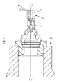
- Fig. 1 the design of a device according to the present invention is schematically disclosed, said device being used to carry out certain steps of the method according to the present invention, i.e., to produce blanks/green bodies for helical drills or milling bodies.
- the method according to the present invention comprises the preparation of a mixture of cemented carbide, cermet or ceramic powder and a carrier, feeding the mixture to the device according to Fig. 1 to produce a drill blank/green body which subsequently is sintered and machined. In this application, said mixture is called extruding mass.
- the device according to the present invention is in the shape of an extruding machine or extruder.
- the extruder according to Fig. 1 comprises a housing 1 and a nozzle 3 that is attached to the housing 1.
- a sleeve 5 is connected to the free end of the nozzle 3, said sleeve 5 defining a cavity 6 that preferably has a cylindrical cross-sectional shape.
- a lid 7 is provided, said lid 7 being displaceable in a direction perpendicular to the axial direction C-C of the sleeve 5, said axial direction C-C being the axial direction also of the nozzle 3 and the housing 1.
- the displacement of the lid 7 closes (either completely or to an essential degree) the free end of the sleeve 5.
- the suitable length of the sleeve 5 depends on various parameters, such as the consistency of the extruding mass and the internal surface friction. Generally, the length of the sleeve 5 is preferably shorter than the length of the shaft portion of the produced blank.
- the device according to the present invention also comprises means (not shown) for transferring the extruding mass from the housing 1 and through the nozzle 3 and the sleeve 5.
- the interior of the nozzle 3 has the cross-section of a drill with external flutes and the interior of the nozzle 3 is twisted in longitudinal direction of the nozzle 3.
- the interior of the nozzle 3 has the geometry of a helical drill. This is indicated in Fig. 1.
- this helical drill geometry is not indicated in the nozzle 3 in Figs. 2-8.
- the nozzle 3 is also equipped with flexible filaments, said filaments being indicated in Figs. 2-8 by dotted lines 9.
- the filaments 9 are anchored upstream of the nozzle 3 by known technique.
- the filaments 9 have a longitudinal extension all the way up to the free end of the sleeve 5 where the ends of the filaments 9 are loose.
- the object of the filaments 9 is to produce internal cooling channels 10 in the blank.
- a helical first blank portion B1 is formed in the nozzle 3, the twisted shape being achieved due to the helical shape of the interior of the nozzle 3, i.e., the mixture that is fed from the housing 1 into the nozzle 3 will be rotated and assumes the shape of a drill body having external helical chip flutes. Simultaneously the filaments 9 are given a twisted configuration inside the blank that fills the nozzle 3.
- the helical blank B1 will leave the nozzle 3 and continue into the cavity 6.
- the first blank portion B1 will have a helical configuration also in the cavity 5 and consequently the filaments 9 will have a twisted configuration in the cavity 6.
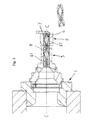
- a further continuation of the extrusion results in the helical blank projecting from the free end of the sleeve 5, see Fig. 2.
- the lid 7 is displaced to a position, see Fig. 3, where the lid 7 seals the free end of the sleeve 5.
- the lid 7 is in the shape of a shearing means that cuts off the projecting part of the helical blank, see Fig. 3. Now, the free end of the blank abuts the lid 7.
- the external, preformed chip flutes of the blank are filled up inside the cavity 6.
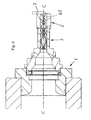
- the pressure in the cavity 6 will increase and the helical filament structure could be disturbed, this being schematically illustrated in Fig. 4.
- the second portion of the blank having a disturbed filament structure is denominated B2.
- the lid 7 seals the free end of the sleeve 5 only partially, i.e., a certain amount of extruding mass is allowed to bypass the lid 7.
- the filaments 9' Due to the non-rotational performance of the extruding mass in the cavity 6, the filaments 9' have a substantially rectilinear extension inside the cavity 6.
- the lid 7 is activated to perform its shearing function, i.e., the portion B2 is separated from the extrusion string, see Fig. 6.
- the third blank portion B3 has a length corresponding to the length of the sleeve 5, see Fig. 6.
- the length of the third blank portion B3 may exceed the length of the sleeve 5, see Fig. 7.
- the lid 7 In order to continue the extrusion process, the lid 7 must be displaced from its position according to Fig. 6 to its position according to Fig. 7.
- the length of the cylindrical third blank portion B3 is increased up to a desired value.
- the friction between the cavity 6 and the extruding mass needs to be decreased.
- a preferred way to effect this is indicated in Fig. 8, i.e., the sleeve 5 is divided into two or more parts, where said parts may be distanced from each other in radial direction relative to the longitudinal direction C-C of the blank and the device according to the present invention.
- the friction is reduced and the recreation of the first, helical blank portion B1 is effected when the extrusion process continues.
- a desired length of the first blank portion B1 has been achieved, said portion B1 is cut off in a suitable way.
- the extrusion process then produces a new first blank portion B1.
- FIG. 3 As regards the cutting off of the first portion B1 to create a drill blank and the continuation of the extrusion process, reference is made to Fig. 3.
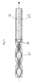
- the drill blank achieved by the extrusion process described above is shown.
- the drill blank comprises a portion B1 having helical chip flutes and a shaft portion B3, preferably of cylindrical shape.
- Internal cooling channels 10 extend along the entire length of the drill blank, said internal cooling channels 10 being essentially rectilinear in the shaft portion B3.
- the next step in the manufacturing process for the drill is to sinter the drill blank. Then the tip of the drill is machined to desired shape and dimension.
- the drill blank is equipped with internal cooling channels.
- a drill blank being void of internal cooling channels.
- the second blank portion B2 is cut off from the third blank portion B3, see Fig. 6. This step is carried out under the prerequisite that the second blank portion B2 holds a disturbed filament structure. However, if no internal cooling channels are to be produced in the blank, then there is no need to cut off the second blank portion B2. In this connection it should also be mentioned that during certain advantageous conditions it might be the case that the filaments are not disturbed when the extruding mass fills out the external flutes to produce the blank portion B2. This could be the case if rigid filaments are used for manufacturing of the internal cooling channels. In both these outlined situations the second blank portion B2 will constitute the shaft of the drill that is manufactured in accordance with the present invention.
- the internal cooling channels 10 in the shaft portion B3 are essentially rectilinear. However, within the scope of the present invention the internal cooling channels may be somewhat twisted in the shaft portion B3. This may occur if the friction between the inner wall of the sleeve 5 and the extruding mass is relatively low.
- the diameter of the blank portion B1 is equal to the diameter of the blank portion B3.
- the sleeve 5 may have a larger diameter than the diameter that is produced by the nozzle 3. It is also possible to manufacture the sleeve in a material that may be widened, e.g., polyurethane. By applying vacuum outside the sleeve 5 the internal diameter of the sleeve 5 may be increased.
- the lid 7 performs both a closing function and a cutting function.
- two separate means are provided, one performing closing and the other performing cutting.
- a blank for a helical drill is manufactured.
- the present invention may also be used to produce for instance deep hole drills that have rectilinear chip flutes and rectilinear internal cooling channels that both extend in axial direction of the drill. In such a case rigid filaments could be especially suitable.
- the cavity 6 preferably has a cylindrical cross-sectional shape. It is feasible within the scope of the present invention that the cavity has a non-cylindrical cross-sectional shape. In an exemplifying and non-restricting purpose, a hexagonal cross-sectional shape may be mentioned.
Landscapes
- Engineering & Computer Science (AREA)
- Mechanical Engineering (AREA)
- Robotics (AREA)
- Drilling Tools (AREA)
- Powder Metallurgy (AREA)
- Extrusion Of Metal (AREA)
- Drilling And Boring (AREA)
Applications Claiming Priority (2)
| Application Number | Priority Date | Filing Date | Title |
|---|---|---|---|
| SE0401150 | 2004-05-04 | ||
| SE0401150A SE527475C2 (sv) | 2004-05-04 | 2004-05-04 | Metod och anordning för tillverkning av ett borrämne eller fräsämne |
Publications (2)
| Publication Number | Publication Date |
|---|---|
| EP1593442A1 true EP1593442A1 (de) | 2005-11-09 |
| EP1593442B1 EP1593442B1 (de) | 2007-08-08 |
Family
ID=32466202
Family Applications (1)
| Application Number | Title | Priority Date | Filing Date |
|---|---|---|---|
| EP05445021A Expired - Lifetime EP1593442B1 (de) | 2004-05-04 | 2005-04-19 | Verfahren und Vorrichtung zur Herstellung eines Bohrer- oder Fräserrohlings |
Country Status (10)
| Country | Link |
|---|---|
| US (1) | US7296497B2 (de) |
| EP (1) | EP1593442B1 (de) |
| JP (1) | JP4723280B2 (de) |
| KR (1) | KR101166404B1 (de) |
| CN (1) | CN1693003B (de) |
| AT (1) | ATE369215T1 (de) |
| BR (1) | BRPI0501443B1 (de) |
| DE (1) | DE602005001886T2 (de) |
| IL (1) | IL168169A (de) |
| SE (1) | SE527475C2 (de) |
Cited By (3)
| Publication number | Priority date | Publication date | Assignee | Title |
|---|---|---|---|---|
| WO2010142458A3 (de) * | 2009-06-12 | 2011-02-17 | Sieber Forming Solutions Gmbh | Verfahren und vorrichtung zur herstellung länglicher bauteile aus metall mit wendelförmigen nuten, insbesondere spiralbohrer oder schnecken |
| EP2298491A1 (de) * | 2009-09-22 | 2011-03-23 | Firma Gühring oHG | Werkzeug mit Kühlmittelkanälen |
| WO2014141174A1 (en) * | 2013-03-15 | 2014-09-18 | Sandvik Intellectual Property Ab | Method of joining sintered parts of different sizes and shapes |
Families Citing this family (22)
| Publication number | Priority date | Publication date | Assignee | Title |
|---|---|---|---|---|
| US20080213720A1 (en) * | 2003-05-13 | 2008-09-04 | Ultradent Products, Inc. | Endodontic instruments manufactured using chemical milling |
| US7743505B2 (en) | 2005-02-23 | 2010-06-29 | Ultradent Products, Inc. | Methods for manufacturing endodontic instruments from powdered metals |
| US7665212B2 (en) * | 2005-02-23 | 2010-02-23 | Ultradent Products, Inc. | Methods for manufacturing endodontic instruments |
| US8637127B2 (en) | 2005-06-27 | 2014-01-28 | Kennametal Inc. | Composite article with coolant channels and tool fabrication method |
| US7687156B2 (en) | 2005-08-18 | 2010-03-30 | Tdy Industries, Inc. | Composite cutting inserts and methods of making the same |
| JP2009535536A (ja) | 2006-04-27 | 2009-10-01 | ティーディーワイ・インダストリーズ・インコーポレーテッド | モジュール型の固定カッターボーリングビット、モジュール型の固定カッターボーリングビット本体及びそれに関連する方法 |
| WO2008051588A2 (en) | 2006-10-25 | 2008-05-02 | Tdy Industries, Inc. | Articles having improved resistance to thermal cracking |
| CN102112642B (zh) | 2008-06-02 | 2013-11-06 | Tdy工业有限责任公司 | 烧结碳化物-金属合金复合物 |
| US8790439B2 (en) | 2008-06-02 | 2014-07-29 | Kennametal Inc. | Composite sintered powder metal articles |
| US8025112B2 (en) | 2008-08-22 | 2011-09-27 | Tdy Industries, Inc. | Earth-boring bits and other parts including cemented carbide |
| IL198375A (en) * | 2009-04-26 | 2013-07-31 | Iscar Ltd | Process for making cutting tools |
| US8272816B2 (en) | 2009-05-12 | 2012-09-25 | TDY Industries, LLC | Composite cemented carbide rotary cutting tools and rotary cutting tool blanks |
| US8308096B2 (en) | 2009-07-14 | 2012-11-13 | TDY Industries, LLC | Reinforced roll and method of making same |
| US9643236B2 (en) | 2009-11-11 | 2017-05-09 | Landis Solutions Llc | Thread rolling die and method of making same |
| US8800848B2 (en) | 2011-08-31 | 2014-08-12 | Kennametal Inc. | Methods of forming wear resistant layers on metallic surfaces |
| US9016406B2 (en) | 2011-09-22 | 2015-04-28 | Kennametal Inc. | Cutting inserts for earth-boring bits |
| EP2596876A1 (de) * | 2011-11-24 | 2013-05-29 | Sandvik Intellectual Property AB | Vorgearbeitetes Rondenwerkzeug sowie Verfahren und Vorrichtung zu seiner Herstellung |
| US10010948B1 (en) * | 2014-10-14 | 2018-07-03 | Matthew W. Hayden | Near-net shaped cutting tools and processes and devices for making the same |
| DE102017212054B4 (de) * | 2017-07-13 | 2019-02-21 | Kennametal Inc. | Verfahren zur Herstellung eines Schneidkopfes sowie Schneidkopf |
| DE102018202941B4 (de) | 2018-02-27 | 2024-01-25 | Kennametal Inc. | Verfahren zur Herstellung eines Rohlings aus Extrusionsmasse sowie Extruder |
| CN112077370B (zh) | 2019-06-13 | 2024-10-01 | 肯纳金属印度有限公司 | 可转位钻头刀片 |
| CN115703157A (zh) | 2021-08-17 | 2023-02-17 | 肯纳金属印度有限公司 | 具有冷却剂系统的可转位钻头组件 |
Citations (2)
| Publication number | Priority date | Publication date | Assignee | Title |
|---|---|---|---|---|
| DE3636798A1 (de) * | 1986-10-29 | 1988-04-07 | Krupp Gmbh | Verfahren zur herstellung von einteiligen gesinterten schneidwerkzeugen in schaftausfuehrung |
| WO2000074870A1 (en) * | 1999-06-03 | 2000-12-14 | Seco Tools Ab (Publ) | Tool, and a method and device for its manufacturing |
Family Cites Families (13)
| Publication number | Priority date | Publication date | Assignee | Title |
|---|---|---|---|---|
| US2954121A (en) * | 1955-03-14 | 1960-09-27 | Donald O Benson | Extrusion of spirally formed article |
| US3422648A (en) * | 1961-10-02 | 1969-01-21 | Jerome H Lemelson | Extrusion apparatus |
| ATE53782T1 (de) * | 1985-10-31 | 1990-06-15 | Krupp Gmbh | Strangpresswerkzeug zur herstellung eines hartmetall- oder keramik-bohrerrohlings. |
| DE3600681A1 (de) | 1985-10-31 | 1987-05-07 | Krupp Gmbh | Hartmetall- oder keramikbohrerrohling sowie verfahren und strangpresswerkzeug zu seiner herstellung |
| DE3714479A1 (de) * | 1987-04-30 | 1988-11-17 | Krupp Gmbh | Strangpresswerkzeug zur herstellung eines bohrerrohlings mit mindestens einer innenliegenden, wendelfoermig verlaufenden spuelbohrung |
| JPH0325251U (de) * | 1989-07-22 | 1991-03-15 | ||
| DE4120166C2 (de) * | 1991-06-19 | 1994-10-06 | Friedrichs Konrad Kg | Strangpreßwerkzeug zur Herstellung eines Hartmetall- oder Keramikstabes mit gedrallten Innenbohrungen |
| JPH05138448A (ja) * | 1991-11-21 | 1993-06-01 | Daido Steel Co Ltd | 油穴付きドリルの製造方法 |
| JPH08225809A (ja) * | 1995-02-23 | 1996-09-03 | Hitachi Metals Ltd | 可塑性混練体の押出し方法 |
| JP3025251U (ja) * | 1995-11-29 | 1996-06-11 | オーエスジー株式会社 | ねじれ流体供給穴付きエンドミル |
| JPH09241706A (ja) * | 1996-03-04 | 1997-09-16 | Toshiba Tungaloy Co Ltd | 孔付き切削工具用焼結体の製造方法 |
| SE514558C2 (sv) * | 1999-07-02 | 2001-03-12 | Seco Tools Ab | Metod och anordning för att tillverka ett verktyg |
| JP3932529B2 (ja) * | 2002-04-26 | 2007-06-20 | 日本ハードメタル株式会社 | 丸棒状回転切削工具用素材及びその製法 |
-
2004
- 2004-05-04 SE SE0401150A patent/SE527475C2/sv unknown
-
2005
- 2005-04-19 DE DE602005001886T patent/DE602005001886T2/de not_active Expired - Lifetime
- 2005-04-19 EP EP05445021A patent/EP1593442B1/de not_active Expired - Lifetime
- 2005-04-19 AT AT05445021T patent/ATE369215T1/de active
- 2005-04-21 IL IL168169A patent/IL168169A/en not_active IP Right Cessation
- 2005-04-29 BR BRPI0501443-3A patent/BRPI0501443B1/pt not_active IP Right Cessation
- 2005-05-02 JP JP2005134249A patent/JP4723280B2/ja not_active Expired - Fee Related
- 2005-05-03 KR KR1020050036914A patent/KR101166404B1/ko not_active Expired - Fee Related
- 2005-05-04 US US11/121,125 patent/US7296497B2/en not_active Expired - Lifetime
- 2005-05-08 CN CN2005100699178A patent/CN1693003B/zh not_active Expired - Fee Related
Patent Citations (2)
| Publication number | Priority date | Publication date | Assignee | Title |
|---|---|---|---|---|
| DE3636798A1 (de) * | 1986-10-29 | 1988-04-07 | Krupp Gmbh | Verfahren zur herstellung von einteiligen gesinterten schneidwerkzeugen in schaftausfuehrung |
| WO2000074870A1 (en) * | 1999-06-03 | 2000-12-14 | Seco Tools Ab (Publ) | Tool, and a method and device for its manufacturing |
Cited By (9)
| Publication number | Priority date | Publication date | Assignee | Title |
|---|---|---|---|---|
| WO2010142458A3 (de) * | 2009-06-12 | 2011-02-17 | Sieber Forming Solutions Gmbh | Verfahren und vorrichtung zur herstellung länglicher bauteile aus metall mit wendelförmigen nuten, insbesondere spiralbohrer oder schnecken |
| CN102802827A (zh) * | 2009-06-12 | 2012-11-28 | 西伯制造有限公司 | 带螺旋槽的金属纵向件特别是螺旋钻头或螺杆的制造方法和装置 |
| EP2298491A1 (de) * | 2009-09-22 | 2011-03-23 | Firma Gühring oHG | Werkzeug mit Kühlmittelkanälen |
| WO2011035769A1 (de) * | 2009-09-22 | 2011-03-31 | Gühring Ohg | Rohling und werkzeug mit kühlkanälen |
| JP2013505141A (ja) * | 2009-09-22 | 2013-02-14 | グーリング オーハーゲー | ブランク及び冷却チャンネル付き工具 |
| US8998543B2 (en) | 2009-09-22 | 2015-04-07 | Guehring Ohg | Blank and tool with cooling channels |
| WO2014141174A1 (en) * | 2013-03-15 | 2014-09-18 | Sandvik Intellectual Property Ab | Method of joining sintered parts of different sizes and shapes |
| US9498824B2 (en) | 2013-03-15 | 2016-11-22 | Sanfvik Intellectual Property Ab | Method of joining sintered parts of different sizes and shapes |
| US10265813B2 (en) | 2013-03-15 | 2019-04-23 | Sandvik Intellectual Property | Method of joining sintered parts of different sizes and shapes |
Also Published As
| Publication number | Publication date |
|---|---|
| EP1593442B1 (de) | 2007-08-08 |
| KR20060047698A (ko) | 2006-05-18 |
| IL168169A (en) | 2009-09-22 |
| US20060027046A1 (en) | 2006-02-09 |
| BRPI0501443A (pt) | 2006-01-10 |
| CN1693003B (zh) | 2012-11-07 |
| SE527475C2 (sv) | 2006-03-21 |
| CN1692998A (zh) | 2005-11-09 |
| DE602005001886D1 (de) | 2007-09-20 |
| DE602005001886T2 (de) | 2008-04-17 |
| ATE369215T1 (de) | 2007-08-15 |
| SE0401150D0 (sv) | 2004-05-04 |
| KR101166404B1 (ko) | 2012-07-23 |
| US7296497B2 (en) | 2007-11-20 |
| JP2005324321A (ja) | 2005-11-24 |
| BRPI0501443B1 (pt) | 2015-07-28 |
| SE0401150L (sv) | 2005-11-05 |
| JP4723280B2 (ja) | 2011-07-13 |
Similar Documents
| Publication | Publication Date | Title |
|---|---|---|
| EP1593442B1 (de) | Verfahren und Vorrichtung zur Herstellung eines Bohrer- oder Fräserrohlings | |
| EP2424710B1 (de) | Verfahren zur herstellung eines schneidwerkzeugs | |
| CN101795812B (zh) | 用于机床的钻孔工具及其制造方法 | |
| US9302332B2 (en) | Twist drill assembly, components for same and method for making same | |
| EP0265445B1 (de) | Kombiniertes bohr- und gewindebohrwerkzeug | |
| EP2596877B1 (de) | Verfahren und Vorrichtung zur Herstellung eines Rohlings für ein rundes Werkzeug | |
| CN101443528B (zh) | 阴型部件和制造阴型部件的方法 | |
| JP2007503322A (ja) | 切れ刃を有するドリルボディ及びその製造方法並びにそのドリルボディを備える穴明け工具 | |
| US20090321145A1 (en) | Threaded nozzle for a cutter bit | |
| KR101086663B1 (ko) | 회전 공구 및 블랭크 | |
| CN118215551A (zh) | 用于钻孔以及去毛刺的组合刀具 | |
| CN1802231B (zh) | 可旋转刀具及坯体 | |
| CN101351614A (zh) | 钻岩刀具、岩钻钻头和生产方法 | |
| JP2003277807A (ja) | 超硬合金製油穴付きドリルの製造方法および超硬合金製油穴付きドリル | |
| JPH026802B2 (de) | ||
| HU207960B (en) | Rotary cutting tool particularly drill, mill and/or reamer and method for producing such tool | |
| CZ355787A3 (en) | Rotary cutting tool and process for producing thereof |
Legal Events
| Date | Code | Title | Description |
|---|---|---|---|
| PUAI | Public reference made under article 153(3) epc to a published international application that has entered the european phase |
Free format text: ORIGINAL CODE: 0009012 |
|
| AK | Designated contracting states |
Kind code of ref document: A1 Designated state(s): AT BE BG CH CY CZ DE DK EE ES FI FR GB GR HU IE IS IT LI LT LU MC NL PL PT RO SE SI SK TR |
|
| AX | Request for extension of the european patent |
Extension state: AL BA HR LV MK YU |
|
| 17P | Request for examination filed |
Effective date: 20060509 |
|
| AKX | Designation fees paid |
Designated state(s): AT BE BG CH CY CZ DE DK EE ES FI FR GB GR HU IE IS IT LI LT LU MC NL PL PT RO SE SI SK TR |
|
| GRAP | Despatch of communication of intention to grant a patent |
Free format text: ORIGINAL CODE: EPIDOSNIGR1 |
|
| GRAS | Grant fee paid |
Free format text: ORIGINAL CODE: EPIDOSNIGR3 |
|
| GRAA | (expected) grant |
Free format text: ORIGINAL CODE: 0009210 |
|
| AK | Designated contracting states |
Kind code of ref document: B1 Designated state(s): AT BE BG CH CY CZ DE DK EE ES FI FR GB GR HU IE IS IT LI LT LU MC NL PL PT RO SE SI SK TR |
|
| REG | Reference to a national code |
Ref country code: GB Ref legal event code: FG4D |
|
| REG | Reference to a national code |
Ref country code: CH Ref legal event code: EP |
|
| REG | Reference to a national code |
Ref country code: IE Ref legal event code: FG4D |
|
| REF | Corresponds to: |
Ref document number: 602005001886 Country of ref document: DE Date of ref document: 20070920 Kind code of ref document: P |
|
| REG | Reference to a national code |
Ref country code: CH Ref legal event code: NV Representative=s name: BOVARD AG PATENTANWAELTE |
|
| REG | Reference to a national code |
Ref country code: SE Ref legal event code: TRGR |
|
| ET | Fr: translation filed | ||
| PG25 | Lapsed in a contracting state [announced via postgrant information from national office to epo] |
Ref country code: FI Free format text: LAPSE BECAUSE OF FAILURE TO SUBMIT A TRANSLATION OF THE DESCRIPTION OR TO PAY THE FEE WITHIN THE PRESCRIBED TIME-LIMIT Effective date: 20070808 Ref country code: IS Free format text: LAPSE BECAUSE OF FAILURE TO SUBMIT A TRANSLATION OF THE DESCRIPTION OR TO PAY THE FEE WITHIN THE PRESCRIBED TIME-LIMIT Effective date: 20071208 Ref country code: BG Free format text: LAPSE BECAUSE OF FAILURE TO SUBMIT A TRANSLATION OF THE DESCRIPTION OR TO PAY THE FEE WITHIN THE PRESCRIBED TIME-LIMIT Effective date: 20071108 Ref country code: LT Free format text: LAPSE BECAUSE OF FAILURE TO SUBMIT A TRANSLATION OF THE DESCRIPTION OR TO PAY THE FEE WITHIN THE PRESCRIBED TIME-LIMIT Effective date: 20070808 Ref country code: ES Free format text: LAPSE BECAUSE OF FAILURE TO SUBMIT A TRANSLATION OF THE DESCRIPTION OR TO PAY THE FEE WITHIN THE PRESCRIBED TIME-LIMIT Effective date: 20071119 Ref country code: NL Free format text: LAPSE BECAUSE OF FAILURE TO SUBMIT A TRANSLATION OF THE DESCRIPTION OR TO PAY THE FEE WITHIN THE PRESCRIBED TIME-LIMIT Effective date: 20070808 |
|
| NLV1 | Nl: lapsed or annulled due to failure to fulfill the requirements of art. 29p and 29m of the patents act | ||
| PG25 | Lapsed in a contracting state [announced via postgrant information from national office to epo] |
Ref country code: PL Free format text: LAPSE BECAUSE OF FAILURE TO SUBMIT A TRANSLATION OF THE DESCRIPTION OR TO PAY THE FEE WITHIN THE PRESCRIBED TIME-LIMIT Effective date: 20070808 |
|
| PG25 | Lapsed in a contracting state [announced via postgrant information from national office to epo] |
Ref country code: BE Free format text: LAPSE BECAUSE OF FAILURE TO SUBMIT A TRANSLATION OF THE DESCRIPTION OR TO PAY THE FEE WITHIN THE PRESCRIBED TIME-LIMIT Effective date: 20070808 |
|
| PG25 | Lapsed in a contracting state [announced via postgrant information from national office to epo] |
Ref country code: GR Free format text: LAPSE BECAUSE OF FAILURE TO SUBMIT A TRANSLATION OF THE DESCRIPTION OR TO PAY THE FEE WITHIN THE PRESCRIBED TIME-LIMIT Effective date: 20071109 Ref country code: DK Free format text: LAPSE BECAUSE OF FAILURE TO SUBMIT A TRANSLATION OF THE DESCRIPTION OR TO PAY THE FEE WITHIN THE PRESCRIBED TIME-LIMIT Effective date: 20070808 |
|
| PG25 | Lapsed in a contracting state [announced via postgrant information from national office to epo] |
Ref country code: SK Free format text: LAPSE BECAUSE OF FAILURE TO SUBMIT A TRANSLATION OF THE DESCRIPTION OR TO PAY THE FEE WITHIN THE PRESCRIBED TIME-LIMIT Effective date: 20070808 Ref country code: CZ Free format text: LAPSE BECAUSE OF FAILURE TO SUBMIT A TRANSLATION OF THE DESCRIPTION OR TO PAY THE FEE WITHIN THE PRESCRIBED TIME-LIMIT Effective date: 20070808 Ref country code: PT Free format text: LAPSE BECAUSE OF FAILURE TO SUBMIT A TRANSLATION OF THE DESCRIPTION OR TO PAY THE FEE WITHIN THE PRESCRIBED TIME-LIMIT Effective date: 20080108 |
|
| PLBE | No opposition filed within time limit |
Free format text: ORIGINAL CODE: 0009261 |
|
| STAA | Information on the status of an ep patent application or granted ep patent |
Free format text: STATUS: NO OPPOSITION FILED WITHIN TIME LIMIT |
|
| PG25 | Lapsed in a contracting state [announced via postgrant information from national office to epo] |
Ref country code: RO Free format text: LAPSE BECAUSE OF FAILURE TO SUBMIT A TRANSLATION OF THE DESCRIPTION OR TO PAY THE FEE WITHIN THE PRESCRIBED TIME-LIMIT Effective date: 20070808 |
|
| 26N | No opposition filed |
Effective date: 20080509 |
|
| PG25 | Lapsed in a contracting state [announced via postgrant information from national office to epo] |
Ref country code: MC Free format text: LAPSE BECAUSE OF NON-PAYMENT OF DUE FEES Effective date: 20080430 |
|
| PG25 | Lapsed in a contracting state [announced via postgrant information from national office to epo] |
Ref country code: EE Free format text: LAPSE BECAUSE OF FAILURE TO SUBMIT A TRANSLATION OF THE DESCRIPTION OR TO PAY THE FEE WITHIN THE PRESCRIBED TIME-LIMIT Effective date: 20070808 |
|
| PG25 | Lapsed in a contracting state [announced via postgrant information from national office to epo] |
Ref country code: IE Free format text: LAPSE BECAUSE OF NON-PAYMENT OF DUE FEES Effective date: 20080421 |
|
| PG25 | Lapsed in a contracting state [announced via postgrant information from national office to epo] |
Ref country code: SI Free format text: LAPSE BECAUSE OF FAILURE TO SUBMIT A TRANSLATION OF THE DESCRIPTION OR TO PAY THE FEE WITHIN THE PRESCRIBED TIME-LIMIT Effective date: 20070808 |
|
| PG25 | Lapsed in a contracting state [announced via postgrant information from national office to epo] |
Ref country code: CY Free format text: LAPSE BECAUSE OF FAILURE TO SUBMIT A TRANSLATION OF THE DESCRIPTION OR TO PAY THE FEE WITHIN THE PRESCRIBED TIME-LIMIT Effective date: 20070808 |
|
| PG25 | Lapsed in a contracting state [announced via postgrant information from national office to epo] |
Ref country code: LU Free format text: LAPSE BECAUSE OF NON-PAYMENT OF DUE FEES Effective date: 20080419 Ref country code: HU Free format text: LAPSE BECAUSE OF FAILURE TO SUBMIT A TRANSLATION OF THE DESCRIPTION OR TO PAY THE FEE WITHIN THE PRESCRIBED TIME-LIMIT Effective date: 20080209 |
|
| PG25 | Lapsed in a contracting state [announced via postgrant information from national office to epo] |
Ref country code: TR Free format text: LAPSE BECAUSE OF FAILURE TO SUBMIT A TRANSLATION OF THE DESCRIPTION OR TO PAY THE FEE WITHIN THE PRESCRIBED TIME-LIMIT Effective date: 20070808 |
|
| REG | Reference to a national code |
Ref country code: CH Ref legal event code: PFA Owner name: SANDVIK INTELLECTUAL PROPERTY AB Free format text: SANDVIK INTELLECTUAL PROPERTY AB# #811 81 SANDVIKEN (SE) -TRANSFER TO- SANDVIK INTELLECTUAL PROPERTY AB# #811 81 SANDVIKEN (SE) |
|
| PGFP | Annual fee paid to national office [announced via postgrant information from national office to epo] |
Ref country code: SE Payment date: 20150413 Year of fee payment: 11 |
|
| REG | Reference to a national code |
Ref country code: FR Ref legal event code: PLFP Year of fee payment: 12 |
|
| REG | Reference to a national code |
Ref country code: SE Ref legal event code: EUG |
|
| PG25 | Lapsed in a contracting state [announced via postgrant information from national office to epo] |
Ref country code: SE Free format text: LAPSE BECAUSE OF NON-PAYMENT OF DUE FEES Effective date: 20160420 |
|
| REG | Reference to a national code |
Ref country code: FR Ref legal event code: PLFP Year of fee payment: 13 |
|
| REG | Reference to a national code |
Ref country code: FR Ref legal event code: PLFP Year of fee payment: 14 |
|
| PGFP | Annual fee paid to national office [announced via postgrant information from national office to epo] |
Ref country code: GB Payment date: 20220303 Year of fee payment: 18 Ref country code: CH Payment date: 20220314 Year of fee payment: 18 |
|
| PGFP | Annual fee paid to national office [announced via postgrant information from national office to epo] |
Ref country code: IT Payment date: 20220310 Year of fee payment: 18 Ref country code: FR Payment date: 20220321 Year of fee payment: 18 |
|
| PGFP | Annual fee paid to national office [announced via postgrant information from national office to epo] |
Ref country code: DE Payment date: 20220302 Year of fee payment: 18 |
|
| PGFP | Annual fee paid to national office [announced via postgrant information from national office to epo] |
Ref country code: AT Payment date: 20220325 Year of fee payment: 18 |
|
| REG | Reference to a national code |
Ref country code: DE Ref legal event code: R119 Ref document number: 602005001886 Country of ref document: DE |
|
| REG | Reference to a national code |
Ref country code: CH Ref legal event code: PL |
|
| REG | Reference to a national code |
Ref country code: AT Ref legal event code: MM01 Ref document number: 369215 Country of ref document: AT Kind code of ref document: T Effective date: 20230419 |
|
| GBPC | Gb: european patent ceased through non-payment of renewal fee |
Effective date: 20230419 |
|
| PG25 | Lapsed in a contracting state [announced via postgrant information from national office to epo] |
Ref country code: GB Free format text: LAPSE BECAUSE OF NON-PAYMENT OF DUE FEES Effective date: 20230419 |
|
| PG25 | Lapsed in a contracting state [announced via postgrant information from national office to epo] |
Ref country code: LI Free format text: LAPSE BECAUSE OF NON-PAYMENT OF DUE FEES Effective date: 20230430 Ref country code: GB Free format text: LAPSE BECAUSE OF NON-PAYMENT OF DUE FEES Effective date: 20230419 Ref country code: FR Free format text: LAPSE BECAUSE OF NON-PAYMENT OF DUE FEES Effective date: 20230430 Ref country code: DE Free format text: LAPSE BECAUSE OF NON-PAYMENT OF DUE FEES Effective date: 20231103 Ref country code: CH Free format text: LAPSE BECAUSE OF NON-PAYMENT OF DUE FEES Effective date: 20230430 Ref country code: AT Free format text: LAPSE BECAUSE OF NON-PAYMENT OF DUE FEES Effective date: 20230419 |
|
| PG25 | Lapsed in a contracting state [announced via postgrant information from national office to epo] |
Ref country code: IT Free format text: LAPSE BECAUSE OF NON-PAYMENT OF DUE FEES Effective date: 20230419 |