EP1593095B1 - Methode et procede de tomographie optique en espace libre de milieux diffus - Google Patents
Methode et procede de tomographie optique en espace libre de milieux diffus Download PDFInfo
- Publication number
- EP1593095B1 EP1593095B1 EP04708596.4A EP04708596A EP1593095B1 EP 1593095 B1 EP1593095 B1 EP 1593095B1 EP 04708596 A EP04708596 A EP 04708596A EP 1593095 B1 EP1593095 B1 EP 1593095B1
- Authority
- EP
- European Patent Office
- Prior art keywords
- light
- model
- optical
- processor
- sensors
- Prior art date
- Legal status (The legal status is an assumption and is not a legal conclusion. Google has not performed a legal analysis and makes no representation as to the accuracy of the status listed.)
- Expired - Lifetime
Links
- 230000003287 optical effect Effects 0.000 title claims description 112
- 238000000034 method Methods 0.000 title claims description 57
- 238000003325 tomography Methods 0.000 title claims description 41
- 238000012545 processing Methods 0.000 claims description 99
- 238000003384 imaging method Methods 0.000 claims description 34
- 230000004044 response Effects 0.000 claims description 15
- 238000004441 surface measurement Methods 0.000 claims description 15
- 238000013480 data collection Methods 0.000 claims description 14
- 230000008569 process Effects 0.000 claims description 7
- 238000005259 measurement Methods 0.000 description 55
- 239000013598 vector Substances 0.000 description 29
- 239000007787 solid Substances 0.000 description 22
- 230000006870 function Effects 0.000 description 20
- 239000002131 composite material Substances 0.000 description 13
- 210000001519 tissue Anatomy 0.000 description 11
- 238000009543 diffuse optical tomography Methods 0.000 description 10
- 238000010521 absorption reaction Methods 0.000 description 8
- 238000010586 diagram Methods 0.000 description 8
- 238000001514 detection method Methods 0.000 description 6
- 239000011159 matrix material Substances 0.000 description 6
- 239000013307 optical fiber Substances 0.000 description 5
- 230000009466 transformation Effects 0.000 description 5
- 241001465754 Metazoa Species 0.000 description 4
- 238000011961 computed axial tomography Methods 0.000 description 4
- 230000014509 gene expression Effects 0.000 description 4
- 238000004458 analytical method Methods 0.000 description 3
- 238000013459 approach Methods 0.000 description 3
- 238000009792 diffusion process Methods 0.000 description 3
- 201000010099 disease Diseases 0.000 description 3
- 208000037265 diseases, disorders, signs and symptoms Diseases 0.000 description 3
- 239000000835 fiber Substances 0.000 description 3
- 230000004907 flux Effects 0.000 description 3
- 206010028980 Neoplasm Diseases 0.000 description 2
- 230000005856 abnormality Effects 0.000 description 2
- 230000005540 biological transmission Effects 0.000 description 2
- 238000012512 characterization method Methods 0.000 description 2
- 239000002872 contrast media Substances 0.000 description 2
- 238000011161 development Methods 0.000 description 2
- 230000018109 developmental process Effects 0.000 description 2
- 230000000694 effects Effects 0.000 description 2
- 230000005284 excitation Effects 0.000 description 2
- 239000007850 fluorescent dye Substances 0.000 description 2
- 238000001727 in vivo Methods 0.000 description 2
- 230000010354 integration Effects 0.000 description 2
- 230000000644 propagated effect Effects 0.000 description 2
- 230000001902 propagating effect Effects 0.000 description 2
- 238000000926 separation method Methods 0.000 description 2
- 238000012546 transfer Methods 0.000 description 2
- 238000001429 visible spectrum Methods 0.000 description 2
- 206010006187 Breast cancer Diseases 0.000 description 1
- 208000026310 Breast neoplasm Diseases 0.000 description 1
- 102000001554 Hemoglobins Human genes 0.000 description 1
- 108010054147 Hemoglobins Proteins 0.000 description 1
- 238000000862 absorption spectrum Methods 0.000 description 1
- 230000004913 activation Effects 0.000 description 1
- 206010003246 arthritis Diseases 0.000 description 1
- 210000004556 brain Anatomy 0.000 description 1
- 238000004364 calculation method Methods 0.000 description 1
- 201000011510 cancer Diseases 0.000 description 1
- 230000004640 cellular pathway Effects 0.000 description 1
- 230000008859 change Effects 0.000 description 1
- 238000003271 compound fluorescence assay Methods 0.000 description 1
- 239000012141 concentrate Substances 0.000 description 1
- 238000010276 construction Methods 0.000 description 1
- 238000013501 data transformation Methods 0.000 description 1
- 238000002059 diagnostic imaging Methods 0.000 description 1
- 229910003460 diamond Inorganic materials 0.000 description 1
- 239000010432 diamond Substances 0.000 description 1
- BFMYDTVEBKDAKJ-UHFFFAOYSA-L disodium;(2',7'-dibromo-3',6'-dioxido-3-oxospiro[2-benzofuran-1,9'-xanthene]-4'-yl)mercury;hydrate Chemical compound O.[Na+].[Na+].O1C(=O)C2=CC=CC=C2C21C1=CC(Br)=C([O-])C([Hg])=C1OC1=C2C=C(Br)C([O-])=C1 BFMYDTVEBKDAKJ-UHFFFAOYSA-L 0.000 description 1
- 239000000975 dye Substances 0.000 description 1
- 238000005516 engineering process Methods 0.000 description 1
- 238000009472 formulation Methods 0.000 description 1
- 238000011223 gene expression profiling Methods 0.000 description 1
- 238000000338 in vitro Methods 0.000 description 1
- 238000011835 investigation Methods 0.000 description 1
- 239000000203 mixture Substances 0.000 description 1
- 210000003205 muscle Anatomy 0.000 description 1
- 230000009826 neoplastic cell growth Effects 0.000 description 1
- 238000012634 optical imaging Methods 0.000 description 1
- 238000006213 oxygenation reaction Methods 0.000 description 1
- 238000005192 partition Methods 0.000 description 1
- 230000037361 pathway Effects 0.000 description 1
- 230000006916 protein interaction Effects 0.000 description 1
- 210000001747 pupil Anatomy 0.000 description 1
- 230000005855 radiation Effects 0.000 description 1
- 239000000523 sample Substances 0.000 description 1
- 230000035945 sensitivity Effects 0.000 description 1
- 150000003384 small molecules Chemical class 0.000 description 1
- 230000003595 spectral effect Effects 0.000 description 1
- 238000012360 testing method Methods 0.000 description 1
- 238000004613 tight binding model Methods 0.000 description 1
- 230000001131 transforming effect Effects 0.000 description 1
Images


Classifications
-
- A—HUMAN NECESSITIES
- A61—MEDICAL OR VETERINARY SCIENCE; HYGIENE
- A61B—DIAGNOSIS; SURGERY; IDENTIFICATION
- A61B5/00—Measuring for diagnostic purposes; Identification of persons
- A61B5/0059—Measuring for diagnostic purposes; Identification of persons using light, e.g. diagnosis by transillumination, diascopy, fluorescence
- A61B5/0062—Arrangements for scanning
- A61B5/0066—Optical coherence imaging
-
- A—HUMAN NECESSITIES
- A61—MEDICAL OR VETERINARY SCIENCE; HYGIENE
- A61B—DIAGNOSIS; SURGERY; IDENTIFICATION
- A61B5/00—Measuring for diagnostic purposes; Identification of persons
- A61B5/0059—Measuring for diagnostic purposes; Identification of persons using light, e.g. diagnosis by transillumination, diascopy, fluorescence
- A61B5/0071—Measuring for diagnostic purposes; Identification of persons using light, e.g. diagnosis by transillumination, diascopy, fluorescence by measuring fluorescence emission
-
- A—HUMAN NECESSITIES
- A61—MEDICAL OR VETERINARY SCIENCE; HYGIENE
- A61B—DIAGNOSIS; SURGERY; IDENTIFICATION
- A61B5/00—Measuring for diagnostic purposes; Identification of persons
- A61B5/0059—Measuring for diagnostic purposes; Identification of persons using light, e.g. diagnosis by transillumination, diascopy, fluorescence
- A61B5/0073—Measuring for diagnostic purposes; Identification of persons using light, e.g. diagnosis by transillumination, diascopy, fluorescence by tomography, i.e. reconstruction of 3D images from 2D projections
-
- A—HUMAN NECESSITIES
- A61—MEDICAL OR VETERINARY SCIENCE; HYGIENE
- A61B—DIAGNOSIS; SURGERY; IDENTIFICATION
- A61B5/00—Measuring for diagnostic purposes; Identification of persons
- A61B5/103—Detecting, measuring or recording devices for testing the shape, pattern, colour, size or movement of the body or parts thereof, for diagnostic purposes
- A61B5/107—Measuring physical dimensions, e.g. size of the entire body or parts thereof
- A61B5/1076—Measuring physical dimensions, e.g. size of the entire body or parts thereof for measuring dimensions inside body cavities, e.g. using catheters
-
- A—HUMAN NECESSITIES
- A61—MEDICAL OR VETERINARY SCIENCE; HYGIENE
- A61B—DIAGNOSIS; SURGERY; IDENTIFICATION
- A61B5/00—Measuring for diagnostic purposes; Identification of persons
- A61B5/103—Detecting, measuring or recording devices for testing the shape, pattern, colour, size or movement of the body or parts thereof, for diagnostic purposes
- A61B5/107—Measuring physical dimensions, e.g. size of the entire body or parts thereof
- A61B5/1077—Measuring of profiles
Definitions
- This invention relates generally to tomography and, more particularly, to optical tomography.
- tomography is often used in construction of detailed images of internal structures of objects.
- Tomography relies upon a selected form of energy being directed toward and passing through the object at more than one angle.
- the energy from the various angles is collected and processed to provide a tomographic image.
- the received signals are typically less intense (i.e., darker) where the object is thicker or more dense, and more intense (i.e., brighter) where the object is thinner or less dense.
- a signal received by a single energy sensor does not contain sufficient information to generate either a two-dimensional or a three-dimensional representation of internal structures of the object.
- signals received by energy sensors arranged in a plane or volume provide sufficient information to generate a three-dimensional representation of internal structures of the object.
- Tomography is used in a variety of systems with a variety of types of transmitted and received energy.
- x-ray Computed Axial Tomography CAT
- x-ray energy is projected through an object, typically at a variety of angles, and a variety of x-ray receivers, at a corresponding variety of angles, are used to receive the x-ray energy.
- a computer is used to generate an image of internal structures of the object in three dimensions from signals received by the variety of x-ray receivers. It should be recognized that x-rays tend to pass through the object in straight lines with relatively little attenuation.
- x-ray CAT system One type of x-ray CAT system is used for medical imaging and the object through which the x-rays are projected is a person. However, the x-ray CAT system can be used to image internal structures of other objects, for example, luggage at an airport.
- optical tomography uses one or more wavelengths of visible or invisible light rather than x-rays.
- x-ray tomography for which x-rays tend to pass through an object in a straight line with relatively little attenuation, light tends to be absorbed and to scatter when passing though an object. Therefore, light does not travel in straight lines when passing through the object. Light also tends to attenuate and to scatter more when passing though a relatively thick object having a relatively non-homogeneous medium, than it tends to attenuate and to scatter when passing through a relatively thin object having a relatively homogeneous medium.
- Diffuse Optical Tomography (DOT) and Fluorescence Molecular Tomography (FMT) are known optical imaging techniques that allow optical tomography imaging of internal structure of body parts of animals and humans.
- DOT is an effective imaging technique capable of imaging hemoglobin concentration and oxygenation.
- DOT can increase the specificity in detecting disease when used in combination with more established examinations (for example for cancer or arthritis detection and characterization).
- DOT is used to study brain activation and to study exercising muscle.
- FMT uses fluorochromes, which absorb light propagating inside of an object and emit light at a longer wavelength (lower energy) than the absorbed light inside of the object, allowing non-invasive in-vivo investigation of functional and molecular signatures in whole tissues of animals and humans.
- FMT enables molecular imaging, i.e., it can probe molecular abnormalities that are the basis of a disease, rather than imaging the end-anatomical effects of the molecular abnormalities as with conventional imaging approaches.
- Specific imaging of molecular targets provides earlier detection and characterization of a disease, as well as earlier and direct molecular assessment of treatment efficacy.
- FMT technology can also transfer typical in-vitro fluorescence assays, such as gene-expression profiling, elucidating cellular pathways or sensing small molecule protein interaction to in-vivo non-invasive imaging applications of large tissues.
- NIR near infrared
- Some conventional optical tomography systems use near infrared (near-IR or NIR) light, instead of light in the visible spectrum when passing through animal tissues, since NIR tends to attenuate less than visible light.
- NIR light instead of light in the visible spectrum provides the ability to image deeper tissues, i.e., thicker tissues, or with higher sensitivity than in the visible light region.
- highly efficient fluorescent probes i.e., appropriately engineered fluorochromes with high molecular specificity emitting in the NIR, has also enabled FMT imaging of deeper tissues.
- Diffuse Optical Tomography uses multiple projections and de-convolves the scattering effect of tissue.
- Conventional DOT and FMT systems include a light source (such as a diode laser and appropriate driver), and an optical switch, which provides light to a group of optical pathways, for example, optical fibers.
- the optical switch directs the light source to selected ones of the optical fibers, one at a time, in a sequence.
- the optical fibers are in direct contact with a diffuse medium to be imaged.
- the single laser source is directed to selected points on the surface of the diffuse medium.
- Light is collected with the use of fiber bundles, placed at multiple points, also in direct contact with the surface of the diffuse medium, and the light is directed though the fiber bundles from the diffuse medium to appropriate light sensors.
- a computer performs tomographic data transformations to provide images for display and storage.
- DOT and FMT systems employ light sources and light sensors in direct contact with the object to be imaged, providing direct contact systems.
- exemplary optical tomography system see D. J. Hawrysz and E. M. Sevick-Muraca, "Developments Toward Diagnostic Breast Cancer Imaging Using Near-Infrared Optical Measurements and Fluorescent Contrast Agents," Neoplasia, vol. 2, pp. 388-417, 2000 .
- the contact light sensors each receive light essentially from a single respective point on the surface of the object.
- Direct contact systems tend to reduce system versatility, limiting the shapes, sizes, and geometries of objects that can be tomograhically imaged with any particular DOT or FMT system.
- Direct contact systems when used to image body parts of a patient, also tend to limit patient comfort.
- Some optical tomography systems can only be used to image objects having a particular shape.
- Wake et al. U.S. patent number 6,211,512 , describes an optical tomography system for use only with objects having a cylindrical geometry.
- WO 2004/008123 describes a method and apparatus for 3-D imaging of internal light sources.
- a method of generating a tomographic image of an object using light energy is provided by generating a mathematical description of at least a portion of the surface of the object and using the mathematical description to generate optical models. At least one of the one or more light sources and/or the light sensors can be spaced apart from the object.
- an optical tomography system 10 includes a data collection system 12 having one or more light sources 14 spaced from an object 18 under test. Each of the one or more light sources 14 projects light 16 toward the object 18. Portions (not shown) of the light 16 which pass through the object 18 are received by one or more light sensors 20 which are disposed proximate, but spaced apart from, the object 18. It should be appreciated that sensors 20 are disposed about the object 20 such that the sensors 20 can receive light, which propagates through the object 18. In one particular exemplary embodiment, the light sensors 20 are disposed to be approximately one centimeter apart from the object 18, proximate a side of the object 18 which is substantially opposite from the side of the object upon which the light 16 is directed.
- the one or more light sensors 20 can be disposed more that one centimeter or less than one centimeter apart from object 18, and can be disposed apart from any side of the object.
- the light sensors are disposed to be between five and twenty-five centimeters from the surface of the object. The separation between the surface of the object and the light sensors is selected in accordance with a variety of factors, including, but not limited to, a distance that can achieve a proper focal depth, while maximizing light collection capacity.
- the light sensors 20 receive the light, which passes through the object 18. Necessarily, since the one or more light sensors 20 are spaced from the object, the light propagates in free space prior to reaching the sensors 20
- the one or more light sensors 20 provide corresponding light sensor signals (e.g. in the form of electrical or other types of signals) to a data processor 24.
- the data processor 24 digitizes, formats, and combines the digitized and formatted light sensor signals into vectors for subsequent processing, the functions of which are described in more detail in conjunction with FIGS. 4A and 5A .
- the light sensors 20 are also adapted to receive fluorescent light generated by fluorochromes internal to the object 18, for example from fluorescent probes injected into the object 18 which tend to coalesce in particular structures or molecules within the object 18.
- the data collection system 12 is coupled to a solution processor 40 and, in the exemplary embodiment of FIG. 1 , the data collection system 12 provides measured optical data to the solution processor 40 through the data processor 24.
- the solution processor 40 provides a solution to an "image problem" described more fully below, which provides image data corresponding to internal structures in the object 18.
- the optical tomography system 10 also includes a surface capture system 28 having one or more surface light sources 30 spaced from the object 16.
- the one or more surface light sources 30 project surface light 32 at the object 18. Portions of the surface light 32 reflect from the surface of the object 18 and are received by one or more surface light sensors 34.
- the one or more surface light sensors 34 receive the surface light reflected from the object 18 and provide corresponding surface light sensor signals (e.g. in the form of electrical or other types of signals) to a surface capture processor 36.
- the surface capture processor 36 In response to the surface light sensor signals, the surface capture processor 36 generates a model (e.g., a mathematical description) of at least a portion of the surface of the object 18 from which the surface light reflects.
- a model e.g., a mathematical description
- the term "mathematical description" can refer to an algorithmic description formed by equations, a numerical description formed by numbers, or both, and is also referred to herein as a model of the surface of the object.
- One surface capture system 28 generates the surface light 32 in a predetermined spatial pattern which is received by the one or more surface light sensors 34 provided as one or more three-dimensional cameras.
- the surface capture system 28 is coupled to a model processor 39.
- the model processor 39 generates one or more optical models.
- the optical models are described more fully below. However, let it suffice here to say that, where the object 18 is diffuse to the propagation of the light 18 through the object, a first optical model generated by the model processor 39 can model the light 16 in the object 18. Furthermore, the first optical model can assume that the object 16 is not only diffuse but also that the object 16 is homogeneous vis-à-vis propagation of the light 16 within the object. In other words, the first optical model can assume that the object 16 has no internal structures.
- optical models referred to herein collectively as a second optical model, which can be generated by the model processor 39 include, but are not limited to, a model of the light 16 as it passes from inside of the object through the surface of the object, a model of the light 16 as it propagates through free space toward the one or more light sensors 20, and a model of optical characteristics of each of the one or more light sensors 16.
- the model processor 39 provides the one or more optical models described above to the solution processor 40. Therefore, the solution processor receives the one or more light sensor signals (e.g., electrical signals) from the data processor and the one or more optical models from the model processor.
- the solution processor receives the one or more light sensor signals (e.g., electrical signals) from the data processor and the one or more optical models from the model processor.
- the solution processor 40 is described more fully in conjunction with FIG. 4A .
- the one or more electrical signals provided by the data processor can correspond to measured optical data associated with the light 16 which has propagated through the object 18 and through free space before being collected by the one or more light sensors 20.
- the one or more optical models provided by the model processor 39 can correspond to a theoretically derived "expected" response of the one or more light sensors 20 assuming that the object 18 is both internally diffuse and also homogeneous, e.g., having no internal structures.
- the solution processor 40 can solve for the unknown distribution in order to establish physical positions and characteristics of the internal structures in the object 18.
- the solution processor 40 provides an output to an image processor 41, which in turn provides data to a display 42.
- the display 42 can provide tomographic images of the internal structures of the object 18.
- the solution processor 40 processes data and optionally can provide the data to the model processor 38.
- the model processor 38 can use the data from the solution processor 40 to adjust the one or more optical models provided by the model processor 39 to the solution processor 40.
- data can be shared between the model processor 39 and the data collection data processor 24.
- the one or more optical models provided by the model processor 39 can be used to adjust the electrical signals provided by data processor 24. This alternate embodiment is described more fully in conjunction with FIGS. 5 and 5A .
- data collection light sources 14 and surface light sources 30 may be provided from the same light hardware which is controlled differently so that the light hardware provides light having different patterns (or characteristics) depending upon the intended purpose (or function) of the light hardware at a particular point in time. For example, if the light hardware were functioning as a data collection system light source 14, the light hardware would provide light having a first pattern or characteristic appropriate for the data collection system function. However, if the same light hardware were functioning as a surface capture system light source 30, the light hardware would provide light having a second pattern or characteristic appropriate for the surface capture system function.
- the light hardware may be provided, for example, as a programmable light source.
- the one or more light sources 14 and the one or more light sensors 20 are adapted to transmit and receive light having wavelengths above or below the wavelength of NIR light, including visible light and including infrared light.
- light sources 14 generate NIR light having a wavelength in the range of about 0.630 to 0.950 microns.
- light sources 14 generate IR light having a wavelength in the range of about 0.950 to 2.0 microns.
- light sources 14 generate visible light having a wavelength in the range of about 0.450 to 0.630 microns.
- the light provided by the one or more light sources 14 can be at the same wavelength or a different wavelength than the light emitted by fluorochromes described above.
- One of ordinary skill in the art will appreciate how to select a particular wavelength of light (or range of wavelengths) for a particular application.
- the one or more surface light sources 30 generate light in the near infrared (NIR), and the one or more surface light sensors 34 are adapted to receive the NIR light accordingly.
- the surface light sources 30 and the surface light sensors 34 are adapted to transmit and receive light having wavelengths above or below the wavelength of NIR light, including visible light and including infrared light.
- light sources 30 generate NIR light having a wavelength in the range of about 0.630 to 0.950 microns.
- light sources 30 generate IR light having a wavelength in the range of about 0.950 to 2.0 microns.
- light sources 30 generate visible light having a wavelength in the range of about 0.450 to 0.630 microns.
- One of ordinary skill in the art will appreciate how to select a particular wavelength of light (or range of wavelengths) for a particular application.
- the one or more light sources 14, when used in the data collection system 12, provide continuous wave (CW) light.
- the one or more light sources 14 are modulated (e.g., in the range of Hz to kHz) or are pulsed (e.g., having pulse widths in the range of microseconds to seconds) to enable source multiplexing and/or background and ambient light separation.
- Corresponding light detection schemes can also be used.
- frequency domain sources i.e., intensity modulated light in one or multiple frequencies (e.g., in the range of MHz to GHz) or time-domain sources, for example pulses of light having different pulse durations (for example, having pulses in the range of femtoseconds to nanoseconds) and corresponding detection systems can be used.
- the one or more light sources 14 provide a planar light source, which illuminates at least a portion of the surface of the object 18. In another embodiment, the one or more light sources 14 illuminate simultaneously a plurality of spots on a surface of the object.
- the one or more light sources 14 illuminate simultaneously a plurality of spots on a surface of the object.
- projection patterns may also include appropriate masks or spatial attenuation patterns (not shown) to interface to the light sensors 16, the light sensors 16 having a dynamic range pertinent to the detection system.
- a mask for example, a stray beam of light cannot directly hit and damage or saturate the light sensors 16.
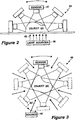
- a portion 43 of an exemplary tomography system includes one or more light sources 46 to provide light 45, which is directed at an object 44.
- the one or more light sources 46 provide a plurality of light beams 45.
- the light 45 is directed from the sources 46 toward the object from one direction.
- the light sources 46 are shown below the object.
- One or more light sensors 47 are disposed above the object to receive the transmitted light 45 having passed through the object 44 and from the object 44 through free space to the one or more light sensors 47.
- the one or more light sensors 47 may be moved to a plurality of different locations as indicated by sensors 47 shown in phantom to receive the light 45.
- the light sources 46 may direct light toward the object from above the object or beside the object in which cases the sensors 47 may be stationary or may be moved, scanning the diffuse pattern of light propagating inside the object 44 and exiting from the surface of the object 44 at different angles.
- a plurality of different light sensors 47 may be disposed in particular locations above the object to receive the light 45. It should be appreciated that the one or more light sensors 47 can be spaced apart from a surface of the object 44.
- a portion 48 of another exemplary optical tomography system includes one or more light sensors 47' and one or more light sources 46'.
- a single light source 46' can be moved to project light about all surfaces of an object 44', and that the sensors 47' are appropriately positioned to receive the light 45' having passed through the object 44' and from the object 44' through free space to the one or more light sensors 47'.
- light 45 may be provided from an array of light sources 46' and the light sensors may be provided from an array of light sensors 47'.
- the light sources 46', 46 ( FIG. 2 ) and the light sensors 47', 47 ( FIG 2 ) are disposed on substantially the same side of the object 44', 44 ( FIG. 2 ). It should be apparent that the light sources 46', 46 and the light sensors can be moved or sequenced in tandem or separately. Also, in yet another embodiment, only the light sensors 47', 47 are moved or sequenced while the light sources 46', 46 remain stationary.
- FIGS. 4-5A are a series of flow diagrams which describe processing performed by a system, which may be similar, for example, to the system described above in conjunction with FIG. 1 , having portions such as those described in conjunction with FIGS. 2 and 3 .
- rectangular elements are herein denoted “processing blocks” and represent processor instructions or groups of instructions (e.g., computer programming code), which may be executed by a processing device (e.g., a personal computer, a general purpose computer or any other type of suitable processor).
- Diamond shaped elements are herein denoted “decision blocks,” and represent processor instructions or groups of instructions (e.g., computer programming code) which affect the execution of the instructions represented by the processing blocks.
- the processing and decision blocks represent steps performed by functionally equivalent circuits such as a digital signal processor circuit or an application specific integrated circuit (ASIC).
- ASIC application specific integrated circuit
- the flow diagrams do not depict the syntax of any particular programming language. Rather, the flow diagrams illustrate the functional information one of ordinary skill in the art requires to fabricate circuits or to generate computer software or other instruction sets needed to perform the processing required as described hereinbelow. It should be noted that many routine program elements, such as initialization of loops and variables and the use of temporary variables are not shown. It will be appreciated by those of ordinary skill in the art that unless otherwise indicated herein, the particular sequence of steps described is illustrative only and can be varied without departing from the spirit of the invention. Thus, unless otherwise stated, the steps described below are unordered meaning that, when possible, the steps can be performed in any convenient or desirable order.
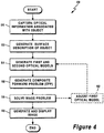
- FIG. 4 a flow diagram 49, which illustrates an exemplary process to generate a tomographic image with a composite forward model (CFP) method begins as shown in processing block 50 in which optical information associated with an object, for example, the object 18 of FIG. 1 , is captured.
- the optical information can include, for example, information provided by the light sensors 20 and the surface light sensors 34 of FIG. 1 .
- Processing then proceeds to processing block 52 in which a surface model (e.g., a three-dimensional mathematical description) of the surface of the object image is generated.
- a surface model e.g., a three-dimensional mathematical description
- One of ordinary skill in the art will understand that there are a variety of ways to optically generate the three-dimensional mathematical description of the surface.
- First and second optical models are generated as shown in processing block 54.
- the first optical model describes light transmission through the object and the second optical model describes light propagation through the surface of the object, in free space about the object and characteristics of light sensors used to capture the optical information captured in processing block 50.
- a composite forward problem is generated as a combination of the first and second optical models provided in processing block 54.
- the CFP and optical information associated with the object are used to solve an image problem as shown in processing block 58.
- processing may proceed to processing block 62 in which the first optical model is adjusted and processing blocks 54-58 are repeated.
- processing flows to processing block 60 where a tomographic image is generated in displayed. Processing then ends.
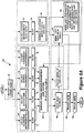
- an exemplary process 63 for generating a tomographic image using a composite for a problem (CFP) approach begins by collecting a series of measurements as shown in processing blocks 66-74.
- calibration measurements, c are collected in processing block 66
- background measurements, B are collected in processing block 68
- intrinsic measurements, I are collected in processing block 70
- fluorescent measurements, F are collected in processing block 72
- surface measurements, R of the object are collected in processing block 74.
- the data collected at processing blocks 66, 70, 72, and 74 is collected in the presence of light generated at processing block 64, which is directed toward the object
- the background measurements collected at processing block 68 can be collected in the absence of the light generated at the processing block 64.
- Calibration measurements can be collected at block 66, where the object, for example the object 18 of FIG. 1 , can be replaced with an object having known characteristics.
- the object can be replaced with an object having a homogeneous internal structure without internal structures.
- the object can be replaced with an object having known internal structures.
- the calibration measurements thus obtained can be compared later in the process 63 with tomographic images generated for the calibration object and the process 63 can be adjusted accordingly.
- the calibration measurements can be collected, for example, with the light sensors 20 of FIG. 1 .
- Background measurements can be collected in processing block 68 in order to record ambient light in the absence of the light transmitted at step 64. Background light signals, corresponding to the background light can be subtracted or otherwise cancelled from subsequent measurements in which with light is transmitted at processing block 64, including from the calibration measurements obtained at processing block 66.
- the background measurements can be collected, for example, with the light sensors 20 of FIG. 1 .
- Intrinsic measurements collected at processing block 70 can include measurements of the light that is generated at processing block 64, the light having passed through the object and having propagated in free space adjacent to the object 18.
- the intrinsic measurements can be collected, for example, with the light sensors 20 of FIG. 1 .
- Fluorescent measurements collected at processing block 72 can include measurements of fluorescent light generated by fluorochromes from within the object, such as that described in conjunction with FIG. 1 .
- the fluorescent measurements can be collected, for example, with the light sensors 20 of FIG. 1 , with or without the presence of the light transmitted at the processing block 64.
- Surface measurements collected at processing block 74 can include measurements of light patterns generated at processing block 64.
- the surface measurements can be collected, for example, with the surface light sensors 34 of FIG. 1 .
- the surface measurements can be collected with the light sensors 20 of FIG. 1 .
- Each of the measurements collected at processing blocks 66-74 are then appropriately digitized and filtered as shown in processing blocks 76-84.
- the surface measurements of the object having been appropriately digitized and filtered at processing block 84 are used to generate a surface model (e.g., a three-dimensional (3D) mathematical description) of a surface the object as shown in processing block 88.
- the three-dimensional surface description of the object is then used to provide a first optical model at processing block 90 as a model of a light field in an object having a shape as described by the three-dimensional surface description.
- the first optical model can assume an object having the shape of the actual object to be imaged, the shape provided by the three-dimensional surface description, and it can assume an object diffuse to the propagation of light like the actual object. However, as described above, the first optical model can assume that the object is homogeneous, having no internal structures.
- Green's function solutions can be updated iteratively or, can use a-priori information to represent solutions that model heterogeneous media as well.
- the first optical model can be calculated based on analytical methods, for example the Born or Rytov approximation.
- analytical methods for example the Born or Rytov approximation.
- different light field models of light in the diffuse medium based on analytical or numerical methods can also be used.
- the three-dimensional surface description of the object provided at the processing block 88 is also used at processing block 92 to provide a second optical model, including, but not limited to, a model of light propagation through the boundary of the surface of the object, a model of light propagation between the object and light receiver, and a model of characteristics of the light receiver.
- the second optical model is further described in conjunction with FIGS. 4A and 6-7E .
- the first and second optical models are then combined to generate a composite forward problem (CFP) as shown in processing block 94.
- CFP composite forward problem
- the CFP can be used to predict the output of the light sensors, for example the light sensors 20 of FIG. 1 , when the object being scanned is homogeneous and has no internal structures.
- the tomographic imaging system 63 is used to scan an object that is not homogeneous or which has internal structures, the measurements collected at the processing block 70 will not agree with the prediction made by the CFP.
- the first optical model generated at the processing block 90 corresponds to a light field description, W.
- the second optical model generated at the processing block 92 corresponds to an operator, T, associated with models of the propagation of light passing through a surface of the object, propagation of the light in free space between the object and the light sensors, and characteristics of the light sensors.
- the three-dimensional surface description of the object generated at the processing block 88 corresponds to a description, S, of the object surface having a data set, R.
- the unknown distribution of optical properties described above, i.e., structures in the diffuse object can be written as a factor, X, corresponding to the unknown distribution above.
- the functions q or g may be analytical or discrete.
- the unknown distribution, X can be minimized, for example, by an iterative solution to the image problem.
- the function, g can be inverted to extract the unknown distribution, X, from the set of measurements, M.
- Other methods can also be used.
- both T and W or W'(s) can be determined theoretically as first and second optical models at processing blocks 90 and 92, whereas measurement vectors, M, can include measured values provided at the processing clock 86.
- M in another method, referred to as a diffuse surface measurement (DSM) method described in conjunction with FIGS. 5 and 5A , provides that measurement vectors, M, can be adjusted with theoretical predictions as well (i.e., the measurement vectors, M, are scaled by a theoretical calculated function or constant associated with an optical model).
- the operators T, W or W'(s), associated with the first and/or the second optical models can be experimentally determined.
- the model of the light field may be adjusted at processing block 98 and processing blocks 90, 92, and 94 may be repeated.
- processing blocks 90, 92, and 94 may be repeated.
- composite measurement vectors, M, provided at processing block 86 are associated with measurements taken with a variety of relative angles between light sources and light sensors, in order to provide tomographic image processing at processing block 100.
- the first optical model generated at block 90 and used to calculate the light field, W, in the object can be calculated based on analytical methods, for example the Born or Rytov approximation.
- the first optical model of the light field in the object can be based upon other analytical or numerical methods.
- a light source can be considered, at position, r s emitting light of wavelength, ⁇ 1 , creating an average intensity, U 0 , within an arbitrarily shaped diffuse volume, V , of average absorption coefficient, ⁇ a , and reduced scattering coefficient, ⁇ s '.
- the normalized Born intensity U (in either absorption/scattering or fluorescence mode) is measured by a light sensor at position r d ⁇ V, also within the volume.
- U 1 , U 2 are two diffuse photon fields measured experimentally.
- U 1 is the fluorescence field and U 2 is the field measured at the excitation wavelength.
- U 1 and U 2 can be a photon field measured before and after the administration of a contrast agent respectively.
- U 2 can be a calibration field measured in a calibration phantom.
- the theoretically calculated fields, U 3 and U 4 can be correspondingly calculated according to an assumption that U 1 , U 2 are the Green's function solutions from the source to the detector, r d , or to a voxel, r, respectively.
- p is an "offset" field typically representing some offset in the data due to detection associated offsets or CD levels.
- the photon propagation wave numbers k 1 (- v ⁇ a 1 / D 1 ) 1/2
- the factor, G is the system's Green function, which describes light propagation from a unit point source to a light sensor and can be written for homogeneous or heterogeneous media.
- the function O ( r ) is the unknown quantity reconstructed (this being the unknown scattering, absorption of fluorochrome mass) and A 0 is a multiplicative factor associated with system gain factors and light propagation constants such as the speed of light.
- DSM diffuse surface measurement
- a flow diagram 120 which illustrates an exemplary process for generating a tomographic image with a diffuse surface measurement (DSM) technique begins as shown at processing block 122 in which optical information associated with an object, for example, the object 18 of FIG. 1 , is captured.
- the optical information can include, for example, information provided by the light sensors 20 and the surface light sensors 34 of FIG. 1 .
- the processing performed at block 122 can be the same as or similar to the processing performed at block 50 of FIG. 4 .
- Processing then proceeds to processing block 124, in which a portion of the optical information collected at block 122 is adjusted to provide altered measured data referred to herein as diffuse surface measurements (DSMs).
- DSMs diffuse surface measurements
- the measured data can be altered in conjunction with the first optical model as described below.
- Processing then proceeds to processing block 126, in which a surface model (e.g., a three-dimensional mathematical description) of the surface of the object image is generated.
- a surface model e.g., a three-dimensional mathematical description
- the processing performed at block 126 can be the same as or similar to the processing performed at block 52 of FIG. 4 .
- the first and second optical models are generated as shown in processing block 128, the first optical model to describe light transmission through the object, and the second optical model to describe light propagation through the surface of the object, in free space about the object, and to describe characteristics of light sensors used to capture the optical information at block 122.
- the first optical model can be used to adjust the measured data at block 124 to provide the DSM.
- the first and second optical models can be the same as or similar to the optical models generated at block 54 of FIG. 4 .
- processing may proceed to processing block 134 in which the first optical model is adjusted in accordance with the image problem and processing blocks 128 and 130 are repeated.
- processing blocks 128 and 130 are repeated.
- processing flows to processing block 132 where a tomographic image is generated and displayed. Processing then ends.
- FIG. 5A in which like elements of FIG. 4A are shown having like reference designations, a DSM method is shown to have many processing blocks which are the same as or similar to processing blocks of the CFP method of FIG. 4A .
- the processing blocks 152-156 can be different.
- DSM diffuse surface measurements
- the composite measurement vectors represent actual measurements of light collected at blocks 66-72.
- the composite measurement vectors are used in an image problem at block 96 of FIG. 4A in order to solve for the unknown distribution, which corresponds to internal structures in the object.
- the image problem solved at processing block 156 receives the diffuse measurement vectors instead of the composite measurement vectors.
- the second optical model 154 or portions of the second model 154 can provide model information to the processing performed at processing block 152.
- the model information provided for this purpose essentially moves the measurements collected at one or more of the processing blocks 66-72 by the light sensors at a reference position apart from the object to a new reference position on the object, as if the measurements had been collected by light sensors on the surface of the object. Therefore, the DSM vectors correspond to calculated measurements of the light as if the measurements had been collected by light sensors on the surface of the object.
- This form has the same form as that described above for the CFP method of FIGS. 4 and 4A , and can be solved using the same methods.
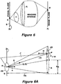
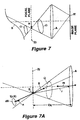
- an imaging system having an aperture, A, corresponding to a solid angle, ⁇ generates an image point, R', of a point R lying on a surface, S.
- the surface, S is a planar surface lying coincident with a focal plane, Z f , associated with the imaging system.
- the image point, R' lies on an image plane, Z i
- the point, R lies on the focal plane, Z f .
- the "stop,” (for example, f-stop in conventional photography) of the imaging system is defined by the smallest aperture at an entrance to the imaging system.
- the aperture, A having an area also denoted as A, delimits the angle of acceptance of the imaging system .
- the plane, S having the point R, again is coincident with the focal plane, Z f , of the imaging system. Therefore, the point, R is in focus in the imaging system ( FIG. 6 ).
- the image plane, Z i of FIG. 6 is not explicitly shown.
- the aperture, A corresponds to an aperture provided within the imaging system of FIG. 6 , and in front of (to the left of) the image plane of FIG. 6 .
- the planar surface, S is located exactly at the focal plane, Z f .
- the planar surface, S includes a differential surface area, dB, about the point, R.
- the differential surface area, dB is shown having a differential surface normal, n.
- the differential surface area, dB, about the point, R is associated with a differential surface area, dA, at the aperture, A.
- the differential surface area, dA is shown having a differential surface normal, m.
- a distance, Z A corresponds to a distance from the focal plane, Z f , to the aperture, A.
- the differential surface area, dB is also shown having a vector, s, in a direction of the differential surface area, dA
- the differential surface area, dA is shown having a vector, u r'-R , in a parallel direction, each corresponding to an intensity of light passing through the respective differential surface area.
- the aperture, A can be off-axis with respect to the differential surface normal, n, or it can be on-axis.
- a vector, r' represents a point corresponding to the point, R, but at the differential surface area dA.
- a vector, O represents the center of the aperture having area, A.
- a total power measured at the image point, R' ( FIG. 6 ), due to the differential surface area, dB, is equivalent to the total power, P , at the point, R, (for example, in Watts) irradiated into the solid angle, ⁇ ( FIG. 6 ):
- P R ⁇ ⁇ I r s n ⁇ s ⁇ d ⁇ B ⁇ d ⁇ ⁇ , ⁇ s ⁇ ⁇
- the vector, n is the differential surface normal to the differential surface area dB
- I ( r,s ) represents the amount of power that at point r flows within a certain solid angle defined by unit vector s for each existing wavelength.
- I ( r,s ) is commonly referred to as the specific intensity. I(r,s) is shown in FIG. 6A .
- the differential surface area, dB may be seen as a "detector area" at the image plane ( FIG. 6 ).
- the differential surface area, dB represents an image of the detector area at the focal plane, Z f .
- the solid angle, ⁇ , ( FIG. 6 ) corresponds to the aperture, A, (i.e., the entrance pupil, lens, etc.) and to the point, R.
- m is the differential surface normal at the aperture, A
- u r ′ ⁇ R r ′ ⁇ R /
- r' is the vector that defines a point in the aperture, A.
- Equation (0.5) represents the exact solution within the Radiative Transfer formulation for the power, P (R'), (by using Equation (0.2)) measured by a light sensor corresponding to the differential surface area, dB', ( dB' ⁇ M 2 dB ), where the prime symbol indicates that the differential surface area dB is the detector area measures at the imaging plane.
- FIG. 6B a small aperture, A, is shown, where the vector, O, represents a center of the aperture, A. Again, the point, R, is in focus in the imaging system ( FIG. 6 ).
- O the vector that represents the center of the aperture, A
- cos ⁇ ⁇ n ⁇ u O ⁇ R
- cos ⁇ ′ m ⁇ u R ⁇ O
- ⁇ is the angle between the normal, n, of the differential surface area, dB, and the unit vector pointing from O towards R
- ⁇ ' is the angle between the surface normal, m, of aperture area, A, and the unit vector pointing from R towards O.
- the above approximation is equivalent, for example, to a light fiber having the aperture, A, and surface normal, m, located a distance, O-R, from a radiating source.
- Equation (0.8) is general for any angular dependence of light radiated from the image plane, i.e., from the surface, S .
- the in focal plane, Z f may be seen as a collection of virtual light sensors (e.g., optical fibers) each having a differential surface area, dB, and each in contact with the surface, S .
- the solid angle integral of the above equation will not be in the whole hemisphere (2 ⁇ ) + and an angular dependence will appear.
- FIG. 6C in which like elements of FIGS. 6-6B are shown having like reference designations, again, the point, R, is in focus in the imaging system ( FIG. 6 ).
- the aperture, A is associated with the imagining system of FIG. 6 .
- the focal plane does not lie on a surface, S, of an object being imaged. Therefore, the surface, S, is substantially out of focus. Also, the in-focus point R is not on the surface, S, to be imaged.
- the total collected power at the point, R' is equivalent to the total power radiated by the point, R, into the solid angle, ⁇ , defined by point, R, and the area, A, of the aperture, A.
- a differential surface area, dS which is out of focus, contributes light energy to point, R'. It will be understood that all of the power that leaves the differential surface area, dS, and passes through the point, R, within the solid angle, ⁇ , is detected at the point, R'.
- the total power measured at the point, R' ( FIG. 7 ), is equivalent to the power that traverses the differential surface area, dB, within the solid angle, ⁇ .
- this virtual surface represents the image of the light sensor at the point, R'.
- the contribution of the differential surface area, dS can be calculated. It will be appreciated that the power radiated must equal the power received. That is, the differential surface area, dS, radiates a certain power into the differential solid angle, ⁇ ⁇ '. From this differential radiation, only those values that fall within the solid angle, ⁇ , will contribute to the total power. Therefore, the differential power measured at the point, R' ( FIG.
- dP R ⁇ ⁇ ′ I f R s m ⁇ s ⁇ d ⁇ B ⁇ d ⁇ ⁇ ′ , ⁇ s ⁇ ⁇
- I f is the specific intensity at the focal plane, Z f
- the surface normal, m is the surface normal of the differential surface area, dB
- the solid angle, ⁇ ⁇ ' is defined by the differential surface area, dS, and the point, R.
- Equation (0.13) the only values of, s, that contribute to the solid angle integral in Equation (0.13) are those that fall within the solid angle, ⁇ ( FIG. 7B ). It should be appreciated that the above equation corresponds to the total power received at the point, R' ( FIG. 7 ), due to a differential surface area, dS.
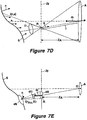
- FIG. 7D in which like elements of FIGS. 6-6C and 7-7C are shown having like reference designations the total power takes into account the complete surface, for those values that fall within the solid angle, ⁇ ( FIGS. 7 and 7B ) through the differential surface area, dB ( FIG. 7B ). This is schematically represented in Fig. 7D .
- FIG. 7E in which like elements of FIGS. 6-6C and 7-7D are shown having like reference designations, for a small aperture, where Z A >>R A , and an out of focus surface, S, it is convenient to return to the contribution of a single differential surface area, dS, given in Equation (0.13).
- dP R I r s n ⁇ s ⁇ ⁇ s ⁇ u r ⁇ O ⁇ s ⁇ u O ⁇ R dS m ⁇ s ⁇ dB
- r RO is the point where the surface, S, and the line given by RO intersect. That is, from Equation (0.18) it is clear that in the case of a small aperture only one element of the surface, S, will contribute to the intensity at a certain pixel. What this represents is that for a very small aperture, A, all of surface, S, will be in focus.
- the differential surface area, dB represents the image of the light sensor at the focal plane, Z f .
- n and m represent the surface normal, n, and the detector normal, m, respectively, as before.
- Function ⁇ is a visibility factor that discards surface points not visible from the light sensor, whereas function f includes the angles of acceptance of the aperture, A, with regards to each surface component, defined by n and m.
- Equation (0.21) may also be envisaged as a convolution of the surface values with the transformation function ⁇ ( r b , r d ).
- Equation (0.21) makes no assumptions regarding the position, orientation, or area of the surface elements or the light detectors but explicitly models these parameters through Equation(0.20).
- Equation (0.21) can be rewritten as a matrix equation where U nc ⁇ R
- describe an imaging system with
- Each matrix element ( b , s ) in U contains the average intensity on a surface element r b ⁇ S created by a source r s as described by Equation (0.1).
- Equation (0.22) can be considered to be the product of a matrix W ⁇ R
- U nc Wc.
- W tends to be very large, the inversion cannot be performed directly.
- iterative techniques such as the algebraic reconstruction technique with randomized projection order (R-ART) can be used, conjugate minimization methods, or other methods.
Claims (29)
- Système (10) de tomographie optique d'un objet (18), comprenant :un système de collecte de données (12) pour recueillir une lumière s'étant déplacée à travers l'objet et dans un espace libre autour de l'objet et pour générer un ou plusieurs signaux en réponse à la lumière, le système de collecte de données comprenant :une ou plusieurs sources lumineuses (14) pour émettre une lumière dirigée pour se propager à travers l'objet, l'objet étant diffus à la propagation de la lumière à travers l'objet ;un ou plusieurs photodétecteurs (20) disposés pour recevoir la lumière qui est passée à travers l'objet, où au moins l'une de l'une ou des plusieurs sources lumineuses et l'un de l'un ou des plusieurs photodétecteurs sont disposés à l'écart de l'objet ; etun processeur de données (24) pour générer l'un ou les plusieurs signaux électriques en réponse à la lumière reçue par l'un ou les plusieurs photodétecteurs.un système de captage de surface (28) pour recevoir une lumière superficielle réfléchie d'une surface de l'objet et pour générer un modèle de surface d'au moins une portion de la surface de l'objet en réponse à la lumière superficielle ;un processeur de modèles (39) couplé au système de captage de surface pour fournir un ou plusieurs modèles optiques associés au modèle de surface ; l'un ou les plusieurs modèles optiques comprenant un modèle de la propagation de la lumière dans l'espace libre entre l'objet et l'un ou les plusieurs photodétecteurs ; etun processeur de solution (40) couplé au système de collecte de données et au processeur de modèles pour fournir une image tomographique de l'objet en réponse au un ou aux plusieurs signaux et au un ou aux plusieurs modèles optiques.
- Système selon la revendication 1, dans lequel l'un ou les plusieurs photodétecteurs correspondent à un photodétecteur.
- Système selon la revendication 1, dans lequel l'une ou les plusieurs sources lumineuses correspondent à une source lumineuse.
- Système selon la revendication 1, dans lequel l'un ou les plusieurs photodétecteurs sont adaptés pour recevoir une lumière fluorescente émise par des fluorochromes à l'intérieur de l'objet.
- Système selon la revendication 1, dans lequel l'un ou les plusieurs modèles optiques comprennent un premier modèle optique pour fournir une description de la lumière dans l'objet en supposant que l'objet est homogène et diffus à la propagation de la lumière, et un deuxième modèle optique formé en modélisant au moins l'un d'entre : la propagation de la lumière associée à la lumière passant à travers la surface de l'objet, et l'un ou les plusieurs photodétecteurs.
- Système selon la revendication 5, dans lequel le processeur de modèles comprend un processeur de problème direct composite (CFP) pour combiner le premier modèle optique et le deuxième modèle optique.
- Système selon la revendication 6, dans lequel le processeur de solution fournit une solution d'image en associant le CFP au un ou aux plusieurs signaux électriques.
- Système selon la revendication 5, dans lequel le processeur de données comprend une processeur de mesure de surface diffuse (DSM) pour ajuster l'un ou les plusieurs signaux électriques en réponse à la sortie du deuxième modèle optique.
- Système selon la revendication 1, dans lequel le système de captage de surface comprend :une source lumineuse de surface pour émettre une lumière superficielle dirigée vers la surface de l'objet ;l'un ou les plusieurs photodétecteurs étant disposés pour recevoir la lumière superficielle réfléchie de la surface de l'objet afin de fournir un ou plusieurs signaux d'image ; etun processeur de captage de surface pour générer le modèle de surface en réponse au un ou aux plusieurs signaux d'image.
- Système selon la revendication 1, dans lequel le système de captage de surface comprend :une source lumineuse de surface pour émettre une lumière superficielle dirigée vers une surface de l'objet ;un photodétecteur de surface disposé pour recevoir la lumière superficielle réfléchie de la surface de l'objet afin de fournir un ou plusieurs signaux d'image ; etun processeur de captage de surface pour générer le modèle de surface en réponse au un ou aux plusieurs signaux d'image.
- Système selon la revendication 1, dans lequel la lumière est une lumière proche de l'infrarouge (NIR) ayant une longueur d'onde d'entre environ 0,630 et 0,950 microns.
- Système selon la revendication 1, dans lequel la lumière est une lumière infrarouge (IR) ayant une longueur d'onde d'entre environ 0,950 et 2,0 microns.
- Système selon la revendication 1, dans lequel la lumière est une lumière visible ayant une longueur d'onde d'entre environ 0,450 et 0,630 microns.
- Système selon la revendication 1, dans lequel le processeur de solution est adapté pour fournir l'image tomographique pour l'objet ayant une forme arbitraire.
- Système selon la revendication 1, comprenant en outre :un processeur d'image couplé au processeur de solution pour traiter l'image tomographique ; etun affichage couplé au processeur d'image pour afficher l'image tomographique.
- Procédé d'imagerie d'un objet par tomographie optique mis en oeuvre par ordinateur, comprenant :capter une lumière s'étant déplacée à travers l'objet et dans un espace libre autour de l'objet, où le fait de capter une lumière comprend :émettre une lumière avec une ou plusieurs sources lumineuses, la lumière étant dirigée pour se propager à travers l'objet, l'objet étant diffus à la propagation de la lumière à travers l'objet ;recevoir une lumière avec un ou plusieurs photodétecteurs, la lumière étant dirigée vers l'objet, où au moins l'une de l'une ou des plusieurs sources lumineuses et l'un de l'un ou des plusieurs photodétecteurs sont disposés à l'écart de l'objet ; ettraiter les sorties de l'un ou des plusieurs photodétecteurs pour générer un ou plusieurs signaux électriques en réponse à la lumière ;générer un ou plusieurs signaux en réponse à la lumière ;générer un modèle de surface d'au moins une portion d'une surface de l'objet ;générer un ou plusieurs modèles optiques associés au modèle de surface, où l'un ou les plusieurs modèles optiques comprennent un modèle de la propagation de la lumière dans l'espace libre entre l'objet et l'un ou les plusieurs détecteurs ; etgénérer une image tomographique de l'objet en réponse au un ou aux plusieurs signaux et au un ou aux plusieurs modèles optiques.
- Procédé selon la revendication 16, dans lequel l'un ou les plusieurs photodétecteurs correspondent à un photodétecteur.
- Procédé selon la revendication 16, dans lequel l'une ou les plusieurs sources lumineuses correspondent à une source lumineuse.
- Procédé selon la revendication 16, comprenant en outre recevoir avec l'un ou les plusieurs photodétecteurs, la lumière fluorescente émise par des fluorochromes à l'intérieur de l'objet.
- Procédé selon la revendication 16, dans lequel générer l'un ou les plusieurs modèles optiques comprend :modéliser, en tant que premier modèle optique, la lumière dans l'objet en supposant que l'objet est homogène et diffus à la propagation de la lumière ; etmodéliser, en tant que deuxième modèle optique, au moins l'un d'entre : la propagation de la lumière associée à la lumière passant à travers la surface de l'objet, et l'un ou les plusieurs photodétecteurs.
- Procédé selon la revendication 20, comprenant en outre combiner le premier modèle optique et le deuxième modèle optique pour fournir un problème direct composite (CFP).
- Procédé selon la revendication 21, dans lequel générer l'image tomographique comprend fournir une solution d'image en associant le CFP au un ou aux plusieurs signaux électriques.
- Procédé selon la revendication 20, comprenant en outre ajuster l'un ou les plusieurs signaux électriques en réponse à la sortie du deuxième modèle optique pour fournir une mesure de surface diffuse (DSM).
- Procédé selon la revendication 16, dans lequel générer le modèle de surface comprend :émettre une lumière superficielle avec une source lumineuse de surface, la lumière superficielle étant dirigée vers la surface de l'objet ;recevoir la lumière superficielle réfléchie de la surface de l'objet avec l'un ou les plusieurs photodétecteurs pour générer un ou plusieurs signaux d'image ;générer le modèle de surface de la au moins une portion de la surface de l'objet en réponse au un ou aux plusieurs signaux d'image.
- Procédé selon la revendication 16, dans lequel générer le modèle de surface comprend :émettre une lumière superficielle avec une source lumineuse de surface, la lumière superficielle étant dirigée vers une surface de l'objet ;recevoir la lumière superficielle réfléchie de la surface de l'objet avec un photodétecteur tridimensionnel pour générer un ou plusieurs signaux d'image ;générer le modèle de surface de la au moins une portion de la surface de l'objet en réponse au un ou aux plusieurs signaux d'image.
- Procédé selon la revendication 16, dans lequel la lumière est une lumière proche de l'infrarouge (NIR) ayant une longueur d'onde d'entre environ 0,630 et 0,950 microns.
- Procédé selon la revendication 16, dans lequel la lumière est une lumière infrarouge (IR) ayant une longueur d'onde d'entre environ 0,950 et 2,0 microns.
- Procédé selon la revendication 16, dans lequel la lumière est une lumière visible ayant une longueur d'onde d'entre environ 0,450 et 0,630 microns.
- Procédé selon la revendication 16, dans lequel la génération de l'image tomographique de l'objet fournit l'image tomographique pour l'objet ayant une forme arbitraire.
Applications Claiming Priority (3)
| Application Number | Priority Date | Filing Date | Title |
|---|---|---|---|
| US44501603P | 2003-02-05 | 2003-02-05 | |
| US445016P | 2003-02-05 | ||
| PCT/US2004/003229 WO2004072906A1 (fr) | 2003-02-05 | 2004-02-05 | Methode et procede de tomographie optique en espace libre de milieux diffus |
Publications (2)
| Publication Number | Publication Date |
|---|---|
| EP1593095A1 EP1593095A1 (fr) | 2005-11-09 |
| EP1593095B1 true EP1593095B1 (fr) | 2019-04-17 |
Family
ID=32869305
Family Applications (1)
| Application Number | Title | Priority Date | Filing Date |
|---|---|---|---|
| EP04708596.4A Expired - Lifetime EP1593095B1 (fr) | 2003-02-05 | 2004-02-05 | Methode et procede de tomographie optique en espace libre de milieux diffus |
Country Status (3)
| Country | Link |
|---|---|
| US (3) | US7647091B2 (fr) |
| EP (1) | EP1593095B1 (fr) |
| WO (1) | WO2004072906A1 (fr) |
Families Citing this family (88)
| Publication number | Priority date | Publication date | Assignee | Title |
|---|---|---|---|---|
| US7383076B2 (en) | 2000-11-27 | 2008-06-03 | The General Hospital Corporation | Fluorescence-mediated molecular tomography |
| EP1402243B1 (fr) | 2001-05-17 | 2006-08-16 | Xenogen Corporation | Procede et appareil pour determiner la profondeur, la brillance et la dimension d'une cible dans une zone du corps humain |
| US7298415B2 (en) | 2001-07-13 | 2007-11-20 | Xenogen Corporation | Structured light imaging apparatus |
| EP2410315B1 (fr) | 2002-06-04 | 2020-04-01 | Visen Medical, Inc. | Volumes d'imagerie avec des géométries arbitraires en tomographie à contact et non contact |
| US7616985B2 (en) * | 2002-07-16 | 2009-11-10 | Xenogen Corporation | Method and apparatus for 3-D imaging of internal light sources |
| US7599731B2 (en) | 2002-07-16 | 2009-10-06 | Xenogen Corporation | Fluorescent light tomography |
| EP1593095B1 (fr) | 2003-02-05 | 2019-04-17 | The General Hospital Corporation | Methode et procede de tomographie optique en espace libre de milieux diffus |
| US7693318B1 (en) | 2004-01-12 | 2010-04-06 | Pme Ip Australia Pty Ltd | Method and apparatus for reconstruction of 3D image volumes from projection images |
| WO2005089637A2 (fr) * | 2004-03-11 | 2005-09-29 | The General Hospital Corporation | Procede et systeme d'imagerie tomographique au moyen de proteines fluorescentes |
| EP1797818A3 (fr) * | 2004-03-11 | 2008-02-13 | The General Hospital Corporation | Procédé et système d'imagerie tomographique utilisant des protéines fluorescentes |
| US8189002B1 (en) | 2004-10-29 | 2012-05-29 | PME IP Australia Pty, Ltd. | Method and apparatus for visualizing three-dimensional and higher-dimensional image data sets |
| US7778392B1 (en) | 2004-11-02 | 2010-08-17 | Pme Ip Australia Pty Ltd | Method of reconstructing computed tomography (CT) volumes suitable for execution on commodity central processing units (CPUs) and graphics processors, and apparatus operating in accord with those methods (rotational X-ray on GPUs) |
| JP4851723B2 (ja) | 2005-03-04 | 2012-01-11 | 富士通株式会社 | 内部構造画像取得装置、内部構造画像取得方法および内部構造画像取得プログラム |
| US8044996B2 (en) * | 2005-05-11 | 2011-10-25 | Xenogen Corporation | Surface construction using combined photographic and structured light information |
| US7947256B2 (en) * | 2005-09-02 | 2011-05-24 | Visen Medical, Inc. | Biocompatible fluorescent imaging agents |
| EP1934202B1 (fr) | 2005-09-02 | 2019-01-09 | Visen Medical, Inc. | Fluorophores proches infrarouge derives d'acide nicotinique et d'acide picolinique |
| WO2007028037A1 (fr) | 2005-09-02 | 2007-03-08 | Visen Medical, Inc. | Marqueurs colorants fluorescents contenant du sulfamide n,n-disubstitue biocompatible |
| US8050735B2 (en) * | 2005-09-08 | 2011-11-01 | Carestream Health, Inc. | Apparatus and method for multi-modal imaging |
| US20090281383A1 (en) * | 2005-09-08 | 2009-11-12 | Rao Papineni | Apparatus and method for external fluorescence imaging of internal regions of interest in a small animal using an endoscope for internal illumination |
| US8041409B2 (en) * | 2005-09-08 | 2011-10-18 | Carestream Health, Inc. | Method and apparatus for multi-modal imaging |
| US20100220836A1 (en) | 2005-09-08 | 2010-09-02 | Feke Gilbert D | Apparatus and method for multi-modal imaging |
| US8660631B2 (en) * | 2005-09-08 | 2014-02-25 | Bruker Biospin Corporation | Torsional support apparatus and method for craniocaudal rotation of animals |
| US8203132B2 (en) * | 2005-09-08 | 2012-06-19 | Carestream Health, Inc. | Apparatus and method for imaging ionizing radiation |
| DE602006020618D1 (de) | 2005-12-22 | 2011-04-21 | Visen Medical Inc | Kombiniertes röntgen- und optisches tomographie-bildgebungssystem |
| FR2898412B1 (fr) | 2006-03-10 | 2008-10-17 | Commissariat Energie Atomique | Procede de reconstruction d'une image de tomographie optique par fluorescence d'un objet a contour quelconque |
| GB0616685D0 (en) * | 2006-08-23 | 2006-10-04 | Warwick Warp Ltd | Retrospective shading approximation from 2D and 3D imagery |
| US10335038B2 (en) | 2006-08-24 | 2019-07-02 | Xenogen Corporation | Spectral unmixing for in-vivo imaging |
| US10775308B2 (en) * | 2006-08-24 | 2020-09-15 | Xenogen Corporation | Apparatus and methods for determining optical tissue properties |
| US20080129961A1 (en) * | 2006-11-30 | 2008-06-05 | Abraham Schwartz | Method and apparatus for measuring quantity of a fluorochrome in a biological environment |
| US7983740B2 (en) * | 2006-12-22 | 2011-07-19 | Washington University | High performance imaging system for diffuse optical tomography and associated method of use |
| US9767599B2 (en) * | 2006-12-29 | 2017-09-19 | X-Rite Inc. | Surface appearance simulation |
| US8019151B2 (en) | 2007-06-11 | 2011-09-13 | Visualization Sciences Group, Inc. | Methods and apparatus for image compression and decompression using graphics processing unit (GPU) |
| US8392529B2 (en) | 2007-08-27 | 2013-03-05 | Pme Ip Australia Pty Ltd | Fast file server methods and systems |
| DE102007042963A1 (de) * | 2007-09-10 | 2009-03-12 | Steinbichler Optotechnik Gmbh | Verfahren und Vorrichtung zur dreidimensionalen Digitalisierung von Objekten |
| US8492734B2 (en) | 2007-10-19 | 2013-07-23 | Visen Medical, Inc. | Imaging systems featuring waveguiding compensation |
| US10311541B2 (en) | 2007-11-23 | 2019-06-04 | PME IP Pty Ltd | Multi-user multi-GPU render server apparatus and methods |
| US8319781B2 (en) | 2007-11-23 | 2012-11-27 | Pme Ip Australia Pty Ltd | Multi-user multi-GPU render server apparatus and methods |
| US9904969B1 (en) | 2007-11-23 | 2018-02-27 | PME IP Pty Ltd | Multi-user multi-GPU render server apparatus and methods |
| US9019287B2 (en) | 2007-11-23 | 2015-04-28 | Pme Ip Australia Pty Ltd | Client-server visualization system with hybrid data processing |
| WO2009067680A1 (fr) | 2007-11-23 | 2009-05-28 | Mercury Computer Systems, Inc. | Procédés et appareil de segmentation automatique d'image |
| WO2009077931A1 (fr) * | 2007-12-17 | 2009-06-25 | Koninklijke Philips Electronics N.V. | Procédé d'évaluation de la qualité d'une mesure et dispositif d'imagerie de l'intérieur d'un milieu |
| WO2009077626A1 (fr) * | 2007-12-19 | 2009-06-25 | Fundacion Para La Investigacion Biomedica Del Hospital Gregorio Marañon | Couveuse pour imagerie à rayonnement non ionisant |
| WO2009120758A1 (fr) | 2008-03-25 | 2009-10-01 | Visen Medical, Inc. | Porte-animal pour imagerie tomographique in vivo avec modes d’application multiples |
| US9480425B2 (en) * | 2008-04-17 | 2016-11-01 | Washington University | Task-less optical mapping of dynamic brain function using resting state functional connectivity |
| CA3162577C (fr) | 2008-05-20 | 2023-09-26 | University Health Network | Dispositif et procede pour imagerie et surveillance par fluorescence |
| EP2344019B1 (fr) | 2008-07-25 | 2013-11-27 | Helmholtz Zentrum München Deutsches Forschungszentrum für Gesundheit und Umwelt (GmbH) | Tomographie opto-acoustique multi-spectrale quantitative (msot) de biomarqueurs tissulaires |
| WO2010064200A1 (fr) * | 2008-12-05 | 2010-06-10 | Koninklijke Philips Electronics N.V. | Procédé et dispositif pour l'examen optique de l'état des articulations |
| EP2449362B1 (fr) | 2009-06-29 | 2016-09-28 | Helmholtz Zentrum München Deutsches Forschungszentrum für Gesundheit und Umwelt (GmbH) | Imagerie thermoacoustique avec extraction quantitative d'une carte d'absorption |
| JP5808741B2 (ja) | 2009-07-27 | 2015-11-10 | ヘルムホルツ・ツェントルム・ミュンヒェン・ドイチェス・フォルシュンクスツェントルム・フューア・ゲズントハイト・ウント・ウムベルト(ゲーエムベーハー)Helmholtz Zentrum MuenchenDeutsches Forschungszentrum fuer Gesundheit und Umwelt (GmbH) | 小動物の光音響イメージング用画像化装置及び画像化方法 |
| AU2010286592B2 (en) | 2009-08-28 | 2015-08-13 | Visen Medical, Inc. | Systems and methods for tomographic imaging in diffuse media using a hybrid inversion technique |
| JP5945226B2 (ja) * | 2009-09-22 | 2016-07-05 | ビセン メディカル, インコーポレイテッド | 拡散媒質の仮想屈折率整合のためのシステムおよび方法 |
| US9220412B2 (en) * | 2009-11-19 | 2015-12-29 | Modulated Imaging Inc. | Method and apparatus for analysis of turbid media via single-element detection using structured illumination |
| US8187002B2 (en) * | 2010-06-29 | 2012-05-29 | Mcneil-Ppc, Inc. | Method for cleaning the oral cavity |
| EP2651309B1 (fr) * | 2010-12-13 | 2020-10-14 | The Trustees of Columbia University in the City of New York | Dispositifs, procédés et systèmes d'imagerie médicale |
| WO2012083349A1 (fr) * | 2010-12-19 | 2012-06-28 | Darling Matthew Ross | Système pour analyse de plaie intégrée |
| US10221159B2 (en) | 2011-05-09 | 2019-03-05 | Visen Medical, Inc. | Carbonic anhydrase targeting agents and methods of using same |
| TWI433051B (zh) | 2011-10-06 | 2014-04-01 | Univ Nat Central | 影像重建方法 |
| US10743768B2 (en) | 2012-10-15 | 2020-08-18 | Visen Medical, Inc. | Systems, methods, and apparatus for imaging of diffuse media featuring cross-modality weighting of fluorescent and bioluminescent sources |
| EP2898326B1 (fr) | 2012-11-07 | 2018-03-14 | Modulated Imaging Inc. | Imagerie modulée efficace |
| EP2742854B1 (fr) | 2012-12-11 | 2021-03-10 | iThera Medical GmbH | Dispositif portatif et procédé pour imagerie opto-acoustique tomographique d'un objet |
| EP2754388B1 (fr) | 2013-01-15 | 2020-09-09 | Helmholtz Zentrum München Deutsches Forschungszentrum für Gesundheit und Umwelt GmbH | Système et procédé pour imagerie opto-acoustique à haut débit de meilleure qualité d'un objet |
| US11244495B2 (en) | 2013-03-15 | 2022-02-08 | PME IP Pty Ltd | Method and system for rule based display of sets of images using image content derived parameters |
| CA2901000C (fr) | 2013-03-15 | 2023-03-14 | Visen Medical, Inc. | Colorants d'heptamethine cyanine pontee par cyclohexyle 4,4-disubstitue et leurs utilisations |
| US8976190B1 (en) | 2013-03-15 | 2015-03-10 | Pme Ip Australia Pty Ltd | Method and system for rule based display of sets of images |
| US10070839B2 (en) | 2013-03-15 | 2018-09-11 | PME IP Pty Ltd | Apparatus and system for rule based visualization of digital breast tomosynthesis and other volumetric images |
| US9509802B1 (en) | 2013-03-15 | 2016-11-29 | PME IP Pty Ltd | Method and system FPOR transferring data to improve responsiveness when sending large data sets |
| US10540803B2 (en) | 2013-03-15 | 2020-01-21 | PME IP Pty Ltd | Method and system for rule-based display of sets of images |
| US11183292B2 (en) | 2013-03-15 | 2021-11-23 | PME IP Pty Ltd | Method and system for rule-based anonymized display and data export |
| US9750413B2 (en) * | 2013-10-03 | 2017-09-05 | National Technology & Engineering Solutions Of Sandia, Llc | Massively parallel diffuse optical tomography |
| JP6769949B2 (ja) | 2014-07-24 | 2020-10-14 | ユニバーシティー ヘルス ネットワーク | 診断目的のためのデータの収集および解析 |
| US11599672B2 (en) | 2015-07-31 | 2023-03-07 | PME IP Pty Ltd | Method and apparatus for anonymized display and data export |
| US9984478B2 (en) | 2015-07-28 | 2018-05-29 | PME IP Pty Ltd | Apparatus and method for visualizing digital breast tomosynthesis and other volumetric images |
| US9730649B1 (en) | 2016-09-13 | 2017-08-15 | Open Water Internet Inc. | Optical imaging of diffuse medium |
| US10909679B2 (en) | 2017-09-24 | 2021-02-02 | PME IP Pty Ltd | Method and system for rule based display of sets of images using image content derived parameters |
| US20210327107A1 (en) * | 2018-03-30 | 2021-10-21 | Perkinelmer Health Sciences, Inc. | Systems and Methods for 3D Reconstruction of Anatomical Organs and Inclusions Using Short-Wave Infrared (SWIR) Projection Tomography |
| US10506181B2 (en) | 2018-03-31 | 2019-12-10 | Open Water Internet Inc. | Device for optical imaging |
| US10778911B2 (en) | 2018-03-31 | 2020-09-15 | Open Water Internet Inc. | Optical transformation device for imaging |
| US10778912B2 (en) | 2018-03-31 | 2020-09-15 | Open Water Internet Inc. | System and device for optical transformation |
| US10966612B2 (en) | 2018-06-14 | 2021-04-06 | Open Water Internet Inc. | Expanding beam optical element |
| US10962929B2 (en) | 2018-09-14 | 2021-03-30 | Open Water Internet Inc. | Interference optics for optical imaging device |
| US10874370B2 (en) | 2019-01-28 | 2020-12-29 | Open Water Internet Inc. | Pulse measurement in optical imaging |
| US10955406B2 (en) | 2019-02-05 | 2021-03-23 | Open Water Internet Inc. | Diffuse optical imaging with multiple beams |
| US11320370B2 (en) | 2019-06-26 | 2022-05-03 | Open Water Internet Inc. | Apparatus for directing optical and acoustic signals |
| US11581696B2 (en) | 2019-08-14 | 2023-02-14 | Open Water Internet Inc. | Multi-channel laser |
| US11622686B2 (en) | 2019-11-22 | 2023-04-11 | Open Water Internet, Inc. | Optical imaging with unshifted reference beam |
| US11819318B2 (en) | 2020-04-27 | 2023-11-21 | Open Water Internet Inc. | Optical imaging from light coherence |
| US11259706B2 (en) | 2020-05-19 | 2022-03-01 | Open Water Internet Inc. | Dual wavelength imaging and out of sample optical imaging |
| US11559208B2 (en) | 2020-05-19 | 2023-01-24 | Open Water Internet Inc. | Imaging with scattering layer |
Family Cites Families (40)
| Publication number | Priority date | Publication date | Assignee | Title |
|---|---|---|---|---|
| US4281645A (en) | 1977-06-28 | 1981-08-04 | Duke University, Inc. | Method and apparatus for monitoring metabolism in body organs |
| JP2645718B2 (ja) | 1988-02-17 | 1997-08-25 | 住友電気工業株式会社 | 光ct装置 |
| US4920491A (en) * | 1988-05-16 | 1990-04-24 | General Electric Company | Enhancement of image quality by utilization of a priori information |
| US5090415A (en) | 1989-02-14 | 1992-02-25 | Hamamatsu Photonics Kabushiki Kaisha | Examination apparatus |
| US5070455A (en) | 1989-11-22 | 1991-12-03 | Singer Imaging, Inc. | Imaging system and method using scattered and diffused radiation |
| US5699798A (en) | 1990-08-10 | 1997-12-23 | University Of Washington | Method for optically imaging solid tumor tissue |
| JPH04122248A (ja) | 1990-09-13 | 1992-04-22 | Res Dev Corp Of Japan | 光断層像画像化装置 |
| JP3217107B2 (ja) | 1992-02-14 | 2001-10-09 | 科学技術振興事業団 | 蛍光断層像測定装置 |
| EP0559978B1 (fr) * | 1992-03-12 | 1998-08-05 | International Business Machines Corporation | Procédé de traitement d'images |
| US6304771B1 (en) | 1993-10-29 | 2001-10-16 | The Trustees Of The University Of Pennsylvania | Systems and methods for imaging fluorophores |
| JP3433508B2 (ja) * | 1993-12-01 | 2003-08-04 | 浜松ホトニクス株式会社 | 散乱吸収体計測方法及び散乱吸収体計測装置 |
| US5391877A (en) | 1994-01-26 | 1995-02-21 | Marks; Michael A. | Combined imaging scanner |
| US5590660A (en) | 1994-03-28 | 1997-01-07 | Xillix Technologies Corp. | Apparatus and method for imaging diseased tissue using integrated autofluorescence |
| JPH08131445A (ja) | 1994-11-14 | 1996-05-28 | Hitachi Ltd | 光計測装置 |
| DE4445214C2 (de) | 1994-12-17 | 2000-06-29 | Laser & Med Tech Gmbh | Verfahren zur Bestimmung und Rekonstruktion räumlicher Verteilungen und Intensitäten von Fluoreszenzfarbstoffen und Vorrichtung zur Durchführung des Verfahrens |
| CN1230118C (zh) | 1995-01-03 | 2005-12-07 | 无创伤诊断技术公司 | 用于生物组织体内测量的光耦合器 |
| JP3819032B2 (ja) | 1995-08-24 | 2006-09-06 | ザ・テキサス・エイ・アンド・エム・ユニバーシティ・システム | 組織およびその他のランダム媒体における蛍光寿命に基づく撮像および分光分析 |
| JP3662376B2 (ja) | 1996-05-10 | 2005-06-22 | 浜松ホトニクス株式会社 | 内部特性分布の計測方法および装置 |
| JP3654325B2 (ja) | 1997-02-13 | 2005-06-02 | 富士写真フイルム株式会社 | 蛍光検出装置 |
| US5762607A (en) * | 1997-03-19 | 1998-06-09 | Schotland; John Carl | Emission tomography system and method using direct reconstruction of scattered radiation |
| US6041132A (en) * | 1997-07-29 | 2000-03-21 | General Electric Company | Computed tomography inspection of composite ply structure |
| US6081322A (en) | 1997-10-16 | 2000-06-27 | Research Foundation Of State Of New York | NIR clinical opti-scan system |
| JP3771364B2 (ja) | 1997-12-12 | 2006-04-26 | 浜松ホトニクス株式会社 | 光ct装置及び画像再構成方法 |
| US6205347B1 (en) | 1998-02-27 | 2001-03-20 | Picker International, Inc. | Separate and combined multi-modality diagnostic imaging system |
| US6377842B1 (en) | 1998-09-22 | 2002-04-23 | Aurora Optics, Inc. | Method for quantitative measurement of fluorescent and phosphorescent drugs within tissue utilizing a fiber optic probe |
| US6205353B1 (en) | 1998-12-22 | 2001-03-20 | Research Foundation Of Cuny | Time-resolved optical backscattering tomographic image reconstruction in scattering turbid media |
| US6028790A (en) | 1999-01-07 | 2000-02-22 | Macronix International Co., Ltd. | Method and device for programming a non-volatile memory cell by controlling source current pulldown rate |
| US6219279B1 (en) | 1999-10-29 | 2001-04-17 | Zilog, Inc. | Non-volatile memory program driver and read reference circuits |
| US7581191B2 (en) | 1999-11-15 | 2009-08-25 | Xenogen Corporation | Graphical user interface for 3-D in-vivo imaging |
| US6377841B1 (en) | 2000-03-31 | 2002-04-23 | Vanderbilt University | Tumor demarcation using optical spectroscopy |
| US7383076B2 (en) | 2000-11-27 | 2008-06-03 | The General Hospital Corporation | Fluorescence-mediated molecular tomography |
| US6615063B1 (en) | 2000-11-27 | 2003-09-02 | The General Hospital Corporation | Fluorescence-mediated molecular tomography |
| US6825928B2 (en) | 2001-12-19 | 2004-11-30 | Wisconsin Alumni Research Foundation | Depth-resolved fluorescence instrument |
| EP2410315B1 (fr) | 2002-06-04 | 2020-04-01 | Visen Medical, Inc. | Volumes d'imagerie avec des géométries arbitraires en tomographie à contact et non contact |
| US7616985B2 (en) * | 2002-07-16 | 2009-11-10 | Xenogen Corporation | Method and apparatus for 3-D imaging of internal light sources |
| EP1593095B1 (fr) | 2003-02-05 | 2019-04-17 | The General Hospital Corporation | Methode et procede de tomographie optique en espace libre de milieux diffus |
| US20080312540A1 (en) | 2004-12-08 | 2008-12-18 | Vasilis Ntziachristos | System and Method for Normalized Flourescence or Bioluminescence Imaging |
| DE602006020618D1 (de) | 2005-12-22 | 2011-04-21 | Visen Medical Inc | Kombiniertes röntgen- und optisches tomographie-bildgebungssystem |
| WO2009009178A2 (fr) | 2007-04-06 | 2009-01-15 | The General Hospital Corporation | Systèmes et procédés pour une imagerie optique utilisant des photons arrivant de manière précoce |
| US8492734B2 (en) | 2007-10-19 | 2013-07-23 | Visen Medical, Inc. | Imaging systems featuring waveguiding compensation |
-
2004
- 2004-02-05 EP EP04708596.4A patent/EP1593095B1/fr not_active Expired - Lifetime
- 2004-02-05 US US10/543,728 patent/US7647091B2/en active Active
- 2004-02-05 WO PCT/US2004/003229 patent/WO2004072906A1/fr active Application Filing
-
2009
- 2009-12-07 US US12/632,150 patent/US7962200B2/en not_active Expired - Lifetime
-
2011
- 2011-05-03 US US13/099,929 patent/US8326406B2/en not_active Expired - Lifetime
Non-Patent Citations (1)
| Title |
|---|
| None * |
Also Published As
| Publication number | Publication date |
|---|---|
| US20100262015A1 (en) | 2010-10-14 |
| US7962200B2 (en) | 2011-06-14 |
| US20110301453A1 (en) | 2011-12-08 |
| US7647091B2 (en) | 2010-01-12 |
| EP1593095A1 (fr) | 2005-11-09 |
| US8326406B2 (en) | 2012-12-04 |
| WO2004072906A1 (fr) | 2004-08-26 |
| US20060173354A1 (en) | 2006-08-03 |
Similar Documents
| Publication | Publication Date | Title |
|---|---|---|
| EP1593095B1 (fr) | Methode et procede de tomographie optique en espace libre de milieux diffus | |
| EP1968431B1 (fr) | Systeme combine d'imagerie tomographique a rayons x et optique | |
| US9964747B2 (en) | Imaging system and method for imaging an object | |
| US7804075B2 (en) | Method and system for tomographic imaging using fluorescent proteins | |
| Chaudhari et al. | Hyperspectral and multispectral bioluminescence optical tomography for small animal imaging | |
| CN101460091B (zh) | 组织的拉曼分析 | |
| US8817257B2 (en) | Method for reconstructing the optical properties of a medium using a combination of a plurality of mellin-laplace transforms of a magnitude comprising a time distribution of a received signal, and associated reconstruction system | |
| US7242997B2 (en) | Diffuse optical tomography system and method of use | |
| US5694938A (en) | Methodology and apparatus for diffuse photon mimaging | |
| US9709733B2 (en) | Hand-held optical probe based imaging system with 3D tracking facilities | |
| US20090240138A1 (en) | Diffuse Optical Tomography System and Method of Use | |
| EP0791207B1 (fr) | Procede et dispositif de representation en image de l'interieur d'un milieu trouble | |
| WO2005089637A9 (fr) | Procede et systeme d'imagerie tomographique au moyen de proteines fluorescentes | |
| US20070146719A1 (en) | Scanning apparatus for optically scanning surfaces | |
| Guggenheim et al. | Multi-modal molecular diffuse optical tomography system for small animal imaging | |
| JP2003532873A (ja) | 不透明媒体における光学式コンピューター断層撮影 | |
| KR20080104307A (ko) | 혼탁한 매체를 이미징하기 위한 디바이스 | |
| EP1797818A2 (fr) | Procédé et système d'imagerie tomographique utilisant des protéines fluorescentes | |
| CN113331788B (zh) | 一种mfmt-xct双模式系统 | |
| US7505135B2 (en) | Method and apparatus for imaging through scattering or obstructing media | |
| Ai | Photoacoustic tomography for prostate imaging by transurethral illumination | |
| Bentz | In Vivo Optical Imaging for Targeted Drug Kinetics and Localization for Oral Surgery and Super-Resolution, Facilitated by Printed Phantoms | |
| Pöschinger | Non-Contact Optical Fluorescence Tomography for Small Animal Imaging: System Development and Multispectral Applications | |
| Pu et al. | Three dimensional localization of cancerous prostate tissue using backscattering scanning polarization imaging and independent component analysis | |
| Wu | Time reversal optical tomography and decomposition methods for detection and localization of targets in highly scattering turbid media |
Legal Events
| Date | Code | Title | Description |
|---|---|---|---|
| PUAI | Public reference made under article 153(3) epc to a published international application that has entered the european phase |
Free format text: ORIGINAL CODE: 0009012 |
|
| 17P | Request for examination filed |
Effective date: 20050905 |
|
| AK | Designated contracting states |
Kind code of ref document: A1 Designated state(s): AT BE BG CH CY CZ DE DK EE ES FI FR GB GR HU IE IT LI LU MC NL PT RO SE SI SK TR |
|
| AX | Request for extension of the european patent |
Extension state: AL LT LV MK |
|
| DAX | Request for extension of the european patent (deleted) | ||
| RIN1 | Information on inventor provided before grant (corrected) |
Inventor name: RIPOLL, JORGE Inventor name: NTZIACHRISTOS, VASILIS |
|
| RIC1 | Information provided on ipc code assigned before grant |
Ipc: G06T 11/00 20060101ALI20130326BHEP Ipc: A61B 5/00 20060101AFI20130326BHEP |
|
| GRAP | Despatch of communication of intention to grant a patent |
Free format text: ORIGINAL CODE: EPIDOSNIGR1 |
|
| INTG | Intention to grant announced |
Effective date: 20130701 |
|
| TPAC | Observations filed by third parties |
Free format text: ORIGINAL CODE: EPIDOSNTIPA |
|
| GRAS | Grant fee paid |
Free format text: ORIGINAL CODE: EPIDOSNIGR3 |
|
| 17Q | First examination report despatched |
Effective date: 20131122 |
|
| INTC | Intention to grant announced (deleted) | ||
| STAA | Information on the status of an ep patent application or granted ep patent |
Free format text: STATUS: GRANT OF PATENT IS INTENDED |
|
| GRAP | Despatch of communication of intention to grant a patent |
Free format text: ORIGINAL CODE: EPIDOSNIGR1 |
|
| INTG | Intention to grant announced |
Effective date: 20180928 |
|
| RIC1 | Information provided on ipc code assigned before grant |
Ipc: A61B 5/00 20060101AFI20130326BHEP Ipc: G06T 11/00 20060101ALI20130326BHEP |
|
| GRAS | Grant fee paid |
Free format text: ORIGINAL CODE: EPIDOSNIGR3 |
|
| GRAA | (expected) grant |
Free format text: ORIGINAL CODE: 0009210 |
|
| STAA | Information on the status of an ep patent application or granted ep patent |
Free format text: STATUS: THE PATENT HAS BEEN GRANTED |
|
| AK | Designated contracting states |
Kind code of ref document: B1 Designated state(s): AT BE BG CH CY CZ DE DK EE ES FI FR GB GR HU IE IT LI LU MC NL PT RO SE SI SK TR |
|
| REG | Reference to a national code |
Ref country code: GB Ref legal event code: FG4D |
|
| REG | Reference to a national code |
Ref country code: CH Ref legal event code: EP |
|
| REG | Reference to a national code |
Ref country code: DE Ref legal event code: R096 Ref document number: 602004053893 Country of ref document: DE |
|
| REG | Reference to a national code |
Ref country code: AT Ref legal event code: REF Ref document number: 1120661 Country of ref document: AT Kind code of ref document: T Effective date: 20190515 Ref country code: IE Ref legal event code: FG4D |
|
| REG | Reference to a national code |
Ref country code: CH Ref legal event code: NV Representative=s name: ING. MARCO ZARDI C/O M. ZARDI AND CO. S.A., CH |
|
| REG | Reference to a national code |
Ref country code: NL Ref legal event code: MP Effective date: 20190417 |
|
| PG25 | Lapsed in a contracting state [announced via postgrant information from national office to epo] |
Ref country code: NL Free format text: LAPSE BECAUSE OF FAILURE TO SUBMIT A TRANSLATION OF THE DESCRIPTION OR TO PAY THE FEE WITHIN THE PRESCRIBED TIME-LIMIT Effective date: 20190417 |
|
| PG25 | Lapsed in a contracting state [announced via postgrant information from national office to epo] |
Ref country code: PT Free format text: LAPSE BECAUSE OF FAILURE TO SUBMIT A TRANSLATION OF THE DESCRIPTION OR TO PAY THE FEE WITHIN THE PRESCRIBED TIME-LIMIT Effective date: 20190819 Ref country code: SE Free format text: LAPSE BECAUSE OF FAILURE TO SUBMIT A TRANSLATION OF THE DESCRIPTION OR TO PAY THE FEE WITHIN THE PRESCRIBED TIME-LIMIT Effective date: 20190417 Ref country code: ES Free format text: LAPSE BECAUSE OF FAILURE TO SUBMIT A TRANSLATION OF THE DESCRIPTION OR TO PAY THE FEE WITHIN THE PRESCRIBED TIME-LIMIT Effective date: 20190417 Ref country code: FI Free format text: LAPSE BECAUSE OF FAILURE TO SUBMIT A TRANSLATION OF THE DESCRIPTION OR TO PAY THE FEE WITHIN THE PRESCRIBED TIME-LIMIT Effective date: 20190417 |
|
| PG25 | Lapsed in a contracting state [announced via postgrant information from national office to epo] |
Ref country code: BG Free format text: LAPSE BECAUSE OF FAILURE TO SUBMIT A TRANSLATION OF THE DESCRIPTION OR TO PAY THE FEE WITHIN THE PRESCRIBED TIME-LIMIT Effective date: 20190717 Ref country code: GR Free format text: LAPSE BECAUSE OF FAILURE TO SUBMIT A TRANSLATION OF THE DESCRIPTION OR TO PAY THE FEE WITHIN THE PRESCRIBED TIME-LIMIT Effective date: 20190718 |
|
| REG | Reference to a national code |
Ref country code: AT Ref legal event code: MK05 Ref document number: 1120661 Country of ref document: AT Kind code of ref document: T Effective date: 20190417 |
|
| REG | Reference to a national code |
Ref country code: DE Ref legal event code: R097 Ref document number: 602004053893 Country of ref document: DE |
|
| PG25 | Lapsed in a contracting state [announced via postgrant information from national office to epo] |
Ref country code: SK Free format text: LAPSE BECAUSE OF FAILURE TO SUBMIT A TRANSLATION OF THE DESCRIPTION OR TO PAY THE FEE WITHIN THE PRESCRIBED TIME-LIMIT Effective date: 20190417 Ref country code: DK Free format text: LAPSE BECAUSE OF FAILURE TO SUBMIT A TRANSLATION OF THE DESCRIPTION OR TO PAY THE FEE WITHIN THE PRESCRIBED TIME-LIMIT Effective date: 20190417 Ref country code: CZ Free format text: LAPSE BECAUSE OF FAILURE TO SUBMIT A TRANSLATION OF THE DESCRIPTION OR TO PAY THE FEE WITHIN THE PRESCRIBED TIME-LIMIT Effective date: 20190417 Ref country code: AT Free format text: LAPSE BECAUSE OF FAILURE TO SUBMIT A TRANSLATION OF THE DESCRIPTION OR TO PAY THE FEE WITHIN THE PRESCRIBED TIME-LIMIT Effective date: 20190417 Ref country code: RO Free format text: LAPSE BECAUSE OF FAILURE TO SUBMIT A TRANSLATION OF THE DESCRIPTION OR TO PAY THE FEE WITHIN THE PRESCRIBED TIME-LIMIT Effective date: 20190417 Ref country code: EE Free format text: LAPSE BECAUSE OF FAILURE TO SUBMIT A TRANSLATION OF THE DESCRIPTION OR TO PAY THE FEE WITHIN THE PRESCRIBED TIME-LIMIT Effective date: 20190417 |
|
| PLBE | No opposition filed within time limit |
Free format text: ORIGINAL CODE: 0009261 |
|
| STAA | Information on the status of an ep patent application or granted ep patent |
Free format text: STATUS: NO OPPOSITION FILED WITHIN TIME LIMIT |
|
| PG25 | Lapsed in a contracting state [announced via postgrant information from national office to epo] |
Ref country code: IT Free format text: LAPSE BECAUSE OF FAILURE TO SUBMIT A TRANSLATION OF THE DESCRIPTION OR TO PAY THE FEE WITHIN THE PRESCRIBED TIME-LIMIT Effective date: 20190417 |
|
| 26N | No opposition filed |
Effective date: 20200120 |
|
| PG25 | Lapsed in a contracting state [announced via postgrant information from national office to epo] |
Ref country code: TR Free format text: LAPSE BECAUSE OF FAILURE TO SUBMIT A TRANSLATION OF THE DESCRIPTION OR TO PAY THE FEE WITHIN THE PRESCRIBED TIME-LIMIT Effective date: 20190417 |
|
| PG25 | Lapsed in a contracting state [announced via postgrant information from national office to epo] |
Ref country code: SI Free format text: LAPSE BECAUSE OF FAILURE TO SUBMIT A TRANSLATION OF THE DESCRIPTION OR TO PAY THE FEE WITHIN THE PRESCRIBED TIME-LIMIT Effective date: 20190417 |
|
| REG | Reference to a national code |
Ref country code: BE Ref legal event code: MM Effective date: 20200229 |
|
| PG25 | Lapsed in a contracting state [announced via postgrant information from national office to epo] |
Ref country code: MC Free format text: LAPSE BECAUSE OF FAILURE TO SUBMIT A TRANSLATION OF THE DESCRIPTION OR TO PAY THE FEE WITHIN THE PRESCRIBED TIME-LIMIT Effective date: 20190417 Ref country code: LU Free format text: LAPSE BECAUSE OF NON-PAYMENT OF DUE FEES Effective date: 20200205 |
|
| PG25 | Lapsed in a contracting state [announced via postgrant information from national office to epo] |
Ref country code: IE Free format text: LAPSE BECAUSE OF NON-PAYMENT OF DUE FEES Effective date: 20200205 |
|
| PG25 | Lapsed in a contracting state [announced via postgrant information from national office to epo] |
Ref country code: BE Free format text: LAPSE BECAUSE OF NON-PAYMENT OF DUE FEES Effective date: 20200229 |
|
| PG25 | Lapsed in a contracting state [announced via postgrant information from national office to epo] |
Ref country code: CY Free format text: LAPSE BECAUSE OF FAILURE TO SUBMIT A TRANSLATION OF THE DESCRIPTION OR TO PAY THE FEE WITHIN THE PRESCRIBED TIME-LIMIT Effective date: 20190417 |
|
| PGFP | Annual fee paid to national office [announced via postgrant information from national office to epo] |
Ref country code: FR Payment date: 20230223 Year of fee payment: 20 Ref country code: CH Payment date: 20230307 Year of fee payment: 20 |
|
| PGFP | Annual fee paid to national office [announced via postgrant information from national office to epo] |
Ref country code: GB Payment date: 20230227 Year of fee payment: 20 Ref country code: DE Payment date: 20230223 Year of fee payment: 20 |
|
| REG | Reference to a national code |
Ref country code: DE Ref legal event code: R071 Ref document number: 602004053893 Country of ref document: DE |
|
| REG | Reference to a national code |
Ref country code: CH Ref legal event code: PL |
|
| REG | Reference to a national code |
Ref country code: GB Ref legal event code: PE20 Expiry date: 20240204 |