EP1591995B1 - Innenraum-Nachrichtübertragungssystem für eine Fahrzeugkabine - Google Patents
Innenraum-Nachrichtübertragungssystem für eine Fahrzeugkabine Download PDFInfo
- Publication number
- EP1591995B1 EP1591995B1 EP04010231.1A EP04010231A EP1591995B1 EP 1591995 B1 EP1591995 B1 EP 1591995B1 EP 04010231 A EP04010231 A EP 04010231A EP 1591995 B1 EP1591995 B1 EP 1591995B1
- Authority
- EP
- European Patent Office
- Prior art keywords
- test signal
- communication system
- indoor communication
- transfer function
- signal
- Prior art date
- Legal status (The legal status is an assumption and is not a legal conclusion. Google has not performed a legal analysis and makes no representation as to the accuracy of the status listed.)
- Expired - Lifetime
Links
- 238000004891 communication Methods 0.000 title claims description 53
- 238000012360 testing method Methods 0.000 claims description 68
- 238000012546 transfer Methods 0.000 claims description 46
- 238000000034 method Methods 0.000 claims description 45
- 238000012545 processing Methods 0.000 claims description 36
- 230000003321 amplification Effects 0.000 claims description 20
- 238000003199 nucleic acid amplification method Methods 0.000 claims description 20
- 230000003044 adaptive effect Effects 0.000 claims description 13
- 238000001228 spectrum Methods 0.000 claims description 11
- 230000004044 response Effects 0.000 claims description 7
- 238000005314 correlation function Methods 0.000 claims description 5
- 238000005311 autocorrelation function Methods 0.000 claims description 4
- 230000008569 process Effects 0.000 claims description 3
- 238000004590 computer program Methods 0.000 claims description 2
- 230000006870 function Effects 0.000 description 37
- 238000003491 array Methods 0.000 description 23
- 230000005540 biological transmission Effects 0.000 description 8
- 230000000694 effects Effects 0.000 description 6
- 238000012986 modification Methods 0.000 description 3
- 230000004048 modification Effects 0.000 description 3
- 230000008901 benefit Effects 0.000 description 2
- 238000010586 diagram Methods 0.000 description 2
- 238000001914 filtration Methods 0.000 description 2
- 230000005236 sound signal Effects 0.000 description 2
- 230000002123 temporal effect Effects 0.000 description 2
- 230000009471 action Effects 0.000 description 1
- 230000002238 attenuated effect Effects 0.000 description 1
- 230000015572 biosynthetic process Effects 0.000 description 1
- 230000006835 compression Effects 0.000 description 1
- 238000007906 compression Methods 0.000 description 1
- 238000013461 design Methods 0.000 description 1
- 238000001514 detection method Methods 0.000 description 1
- 238000003780 insertion Methods 0.000 description 1
- 230000037431 insertion Effects 0.000 description 1
- 230000008092 positive effect Effects 0.000 description 1
- 238000012805 post-processing Methods 0.000 description 1
- 230000002787 reinforcement Effects 0.000 description 1
- 238000005070 sampling Methods 0.000 description 1
- 230000008054 signal transmission Effects 0.000 description 1
- 238000003786 synthesis reaction Methods 0.000 description 1
Images

Classifications
-
- H—ELECTRICITY
- H03—ELECTRONIC CIRCUITRY
- H03G—CONTROL OF AMPLIFICATION
- H03G5/00—Tone control or bandwidth control in amplifiers
- H03G5/16—Automatic control
- H03G5/165—Equalizers; Volume or gain control in limited frequency bands
-
- H—ELECTRICITY
- H04—ELECTRIC COMMUNICATION TECHNIQUE
- H04R—LOUDSPEAKERS, MICROPHONES, GRAMOPHONE PICK-UPS OR LIKE ACOUSTIC ELECTROMECHANICAL TRANSDUCERS; DEAF-AID SETS; PUBLIC ADDRESS SYSTEMS
- H04R29/00—Monitoring arrangements; Testing arrangements
- H04R29/001—Monitoring arrangements; Testing arrangements for loudspeakers
-
- H—ELECTRICITY
- H04—ELECTRIC COMMUNICATION TECHNIQUE
- H04R—LOUDSPEAKERS, MICROPHONES, GRAMOPHONE PICK-UPS OR LIKE ACOUSTIC ELECTROMECHANICAL TRANSDUCERS; DEAF-AID SETS; PUBLIC ADDRESS SYSTEMS
- H04R3/00—Circuits for transducers, loudspeakers or microphones
- H04R3/02—Circuits for transducers, loudspeakers or microphones for preventing acoustic reaction, i.e. acoustic oscillatory feedback
-
- H—ELECTRICITY
- H04—ELECTRIC COMMUNICATION TECHNIQUE
- H04R—LOUDSPEAKERS, MICROPHONES, GRAMOPHONE PICK-UPS OR LIKE ACOUSTIC ELECTROMECHANICAL TRANSDUCERS; DEAF-AID SETS; PUBLIC ADDRESS SYSTEMS
- H04R2499/00—Aspects covered by H04R or H04S not otherwise provided for in their subgroups
- H04R2499/10—General applications
- H04R2499/13—Acoustic transducers and sound field adaptation in vehicles
-
- H—ELECTRICITY
- H04—ELECTRIC COMMUNICATION TECHNIQUE
- H04R—LOUDSPEAKERS, MICROPHONES, GRAMOPHONE PICK-UPS OR LIKE ACOUSTIC ELECTROMECHANICAL TRANSDUCERS; DEAF-AID SETS; PUBLIC ADDRESS SYSTEMS
- H04R5/00—Stereophonic arrangements
- H04R5/02—Spatial or constructional arrangements of loudspeakers
Definitions
- the invention is directed to an indoor communication system for a vehicular cabin and to a method for automatically determining an equalizing filter characteristic for an indoor communication system of a vehicular cabin.
- a noisy environment can render communication between different persons very difficult or almost impossible, particularly if the noise is at a similar loudness level as the speech.
- a strong background noise is present in a vehicular cabin (such as the passenger compartment of a car) due to engine and wind noise.
- Further possible noise sources that can deteriorate the mutual understanding of the people are the loudspeakers of a car radio or a handsfree telephone system. Due to the multitude of different noise sources, a communication both between the front seat and back seat passengers and between the driver and the front seat passenger, for example, is very difficult, in particular when the vehicle is moving at a high speed.
- US 4 739 513 A discloses an apparatus for measuring and correcting characteristics in sound fields.
- a sound field output by an audio system of a vehicle is optimized for a listener.
- EP 0 898 364 A discloses systems and methods for measuring and correcting acoustic characteristics in sound fields.
- US 5 386 478 A a system and a method to reduce noise inside a motor car passenger compartment is described.
- US 5 170 433 A teaches provision of a microphone array in a vehicle cabin and beamforming of the microphones.
- US 6 674 865 B1 discloses an automatic gain control for a cabin communication system for improving clarity of a voice spoken within a movable interior cabin having ambient noise includes a microphone for receiving the spoken voice and the ambient noise and for converting the spoken voice and the ambient noise into a first audio signal having a first component corresponding to the spoken voice and a second component corresponding to the ambient noise.
- EP 1 077 584 A2 discloses a signal loss compensation method that determines the acoustic signal transmission path between a pair of spaced intercom points within an automobile passenger compartment, for providing a transmission function parameter, which is used for controlling the acoustic signal level at a given position of the acoustic signal path.
- WO 03/010996 A2 discloses a sound reinforcement system comprising an equalizing means, an adaptive echo cancelling filter and a beamformer wherein a noise signal is used for estimating a transfer function.
- JP 2050 090856 A teaches the determination of a transfer function of an indoor communication system based on a test signal and various combinations of loudspeakers and microphones.
- JP 1992 047787 A teaches a sound field control system comprising means for measuring a transfer function and adapted to reduce howling effects.
- an indoor communication system for cars has been proposed to improve communication between people located in a passenger compartment.
- one microphone is associated with each passenger seat, including the driver's seat. This means that in the vicinity of each seat or in the vicinity of a passenger's head sitting on a seat, a microphone is arranged.
- Each microphone records the speech of the respective passenger and the corresponding signals are output via loudspeakers in the car.
- the loudspeakers already present in the car can be associated to the different passenger seats. For example, if a loudspeaker is mounted in each door, the respective loudspeaker can be associated to the person sitting next to it. This allows for outputting the speech signals mainly at loudspeakers corresponding to passengers other than the current speaker. For example, if the driver is speaking, the corresponding speech signal may be output at the different loudspeakers except the for the driver's loudspeaker(s).
- This object is solved by a method for automatically determining an equalizing filter characteristic for an indoor communication system of a vehicular cabin according to claim 1 and by an indoor communication system for a vehicular cabin according to claim 12.
- the invention provides a method for automatically determining an equalizing filter characteristic for an indoor communication system of a vehicular cabin, the indoor communication system comprising at least one loudspeaker and at least one microphone array connected to a beamformer, the at least one loudspeaker associated with the at least one microphone array and a corresponding speaker position, comprising the steps of:
- a frequency for which the transfer function has a (global or local) maximum is considered as possible feedback frequency.
- microphone (if not explicitly used in the context of microphone arrays) is used to denote a single microphone or, in other words, a microphone not being part of a microphone array.
- a loudspeaker may comprise several components such as a high-frequency and a low-frequency unit.
- a transfer function is a function characterizing the transmission properties of a transmission path. These transmission properties can result from the geometry of the room where the test signal is transmitted from one or several loudspeakers to one or several microphones and/or microphone arrays and possible objects located therein. Furthermore, the transmission properties can also be influenced by electronic components along the signal path, e.g., between the signal generator and the loudspeaker.
- the received signal is a function, namely the transfer function, of the original test signal.
- the test signal is a signal as generated by a signal generator.
- a beamformer processes signals emanating from a microphone array to obtain a combined signal.
- beamforming comprises delay compensation and summing of the signals. Beamforming allows providing a specific directivity pattern for a microphone array.
- a test signal is used to determine the transmission properties of the signal path as a function in the frequency domain. Based on these transmission properties, an equalizing filter characteristic is determined.
- this method allows for the detection of possible feedback frequencies via the transfer function that can be used for an appropriate modification of a signal to be output in order to reduce the occurrence of feedback effects.
- the indoor communication system for which this method is used can comprise one or several (single) microphones and/or one or several microphone arrays. Such a microphone or microphone array can be associated to a potential speaker (passenger) and be mounted at appropriate positions. Furthermore, the indoor communication system can also comprise one or several loudspeakers associated with a microphone or microphone array and the corresponding speaker position.
- the predetermined test signal can be emitted by (exactly) one loudspeaker.
- a transfer function is obtained and a corresponding equalizing filter characteristic can be determined such that for each pair, an appropriate equalizing filter is provided.
- the test signal can be received simultaneously by each microphone or microphone array. This allows to determine in parallel an equalizing filter characteristic for each of these microphones or microphone arrays with respect to a given loudspeaker.
- Step a) can comprise emitting binary white noise or colored noise, particularly pink noise.
- white noise all frequencies (in the present context, usually, only frequencies within the range of human hearing are considered) are present and uniformly distributed. This enables a comparison of original test signal and received test signal in a very simple way. A more pleasing sound for people being present in the vehicular cabin is obtained using colored noise, particularly pink noise. Pink noise can be obtained by filtering white noise to reduce the volume at each octave.
- Step c) can comprise processing the test signal and the received test signal in the time domain, in particular, using an adaptive filter or using an estimation method based on a periodogram, an autocorrelation function or cross-correlation function.
- Processing in the time domain is particularly useful when using broadband test signals.
- an NLMS (normalized least means squared) algorithm as described, e.g., in S. Haykin, B. Widrow, Least-Mean-Square Adaptive Filtering, John Wiley and Sons, 2003 ) can be used After processing in the time domain, the impulse response is to be transformed into the frequency domain so as to obtain the transfer function.
- step a) can comprise emitting band pass noise with variable center frequency. In this case, however, all frequency ranges should be activated.
- step c) can comprise determining the square root of the quotient of the short time power spectrum of the received test signal and the short time power spectrum of the test signal for each band pass noise.
- the transfer function can also be obtained in this way.
- Step d) can comprise determining a global extremum of the magnitude of the transfer function.
- the global maximum with respect to the overall frequency range to be considered has a high probability of constituting a feedback frequency.
- Step d) can further comprise determining a local extremum for which the magnitude of the transfer function differs not more than a predetermined amount from the magnitude of the transfer function at a global extremum. Particularly in the case of local maxima, other frequencies (in addition to the global maximum) are also considered as possible feedback frequencies.
- Step d) can further comprise providing an attenuation of a predetermined frequency band of a signal being centered at a determined maximum and/or providing an amplification of a predetermined frequency band being centered at a determined minimum.
- the (broadband) stability limit can be improved by the value corresponding to the applied attenuation. Particularly if a small attenuation bandwidth is chosen, the acoustic impression of an audio signal in the vehicular cabin will hardly differ.
- the attenuating step can be performed using a nonlinear phase filter. This has the advantage that inserting small delay time differences when reproducing mono signals can improve the subjective quality impression of the signal.
- the invention also provides a method for automatically determining a maximum amplification value of an indoor communication system of a vehicular cabin, comprising the steps of: automatically determining an equalizing filter characteristic using the method of one of the above-described embodiments for a predetermined loudspeaker.
- the invention provides a computer program product comprising one or more computer readable media having computer-executable instructions for performing the steps of the above-described methods.
- an indoor communication system for a vehicular cabin comprising:
- each microphone array is connected to the signal processing means via a beamformer. It is to be understood that microphones and microphone arrays can both be used in a vehicular cabin. For example, microphone arrays can be provided for the front passengers whereas for back passengers, only single microphones are present.
- the indoor communication system can comprise at least two loudspeakers and the signal generator can be connected to the at least two loudspeakers in such a way that the test signal can be separately emitted by each loudspeaker. This allows to separately perform the previously described methods for each loudspeaker independently of the other loudspeakers.
- the signal generator can be configured to emit binary white noise or colored noise, particularly pink noise.
- the signal processing means of the indoor communication system can be configured to process the test signal and the received test signal in the time domain, in particular, using an adaptive filter or using an estimation method based on a periodogram, an autocorrelation function or a cross-correlation function.
- the signal processing means can comprise an NLMS (normalized least means squared) adaptive filter.
- the signal generator can be configured to emit band pass noise with variable center frequency.
- the signal processing means can be configured to determine the square root of the quotient of the short time power spectrum of the received test signal and the short time power spectrum of the test signal for each band pass noise.
- the signal processing means can be configured to determine a global extremum of the magnitude of the transfer function.
- the signal processing means can be configured to further determine a local extremum for which the magnitude of the transfer function differs not more than a predetermined amount from the magnitude of the transfer function and a global extremum.
- the signal processing means can be configured to automatically attenuate a predetermined frequency band being centered at a determined maximum and/or to amplify a predetermined frequency band being centered at a determined minimum.
- the signal processing means can comprise a nonlinear phase filter for attenuating a predetermined frequency band.
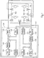
- the vehicular cabin 100 comprises four passengers' seats (not shown) and four passengers 101. With each passenger, a microphone array comprising two microphones 102 and a loudspeaker 103 are associated. For the front passengers, the microphone arrays are arranged in the center between the passengers. They can be provided at the car roof, for example. At the rear seats, the microphone arrays are provided at the left and right side of the passengers, respectively, for example, in the car door.
- Each loudspeaker can comprise a high-frequency and a low-frequency unit, for example.
- the microphone arrays record signals.
- the signals emanating from the microphone arrays enter a digital signal processing means 104 and 104'.
- a first signal processing means 104 is responsible for processing the signals emanating from the microphones associated with the rear passengers and a second digital signal processing means 104' is associated with the signals emanating from the microphones associated with the front passengers.
- the signals emanating from the microphone arrays are processed by an analog/digital converter (not shown). This is followed by a beamformer 105 and 105'.
- the beamformers serve to obtain information on the temporal signal behavior and also spatial information about the signal sources of both wanted (e.g. passengers) and noise signal sources (e.g. car radio loudspeakers). Different types of beamformers (e.g., adaptive beamformers) can be used for the present invention.
- echo and feedback components are subtracted from the signal via adaptive echo cancellation 106 and 106' and feedback cancellation 107 and 107'.
- Adaptive notch filters 108 and 108' can detect potential feedback frequencies and attenuate these.
- Attenuators are controlled such that, for example, only the loudest speaker is switched through.
- a post processing 109 and 109' can apply a boundary characteristic.
- the output signals of the digital signal processing means 104 and 104' are fed, first of all, to corresponding loudspeakers 103.
- signals emanating from rear microphone arrays can only be output by front loudspeakers and vice versa.
- the system can also be configured, for example, such that the processed signals can be output by all loudspeakers except the loudspeakers corresponding to the microphone array of the input signals.
- the processed signals are also fed to feedback cancellation 107 and 107' of the same digital signal processing means and also to echo cancellation means 106 and 106' of the other digital signal processing means.
- directional microphones can be used instead of microphone arrays.
- FIG. 2 An example of an indoor communication system and the method for operating the same is illustrated in Fig. 2 . Again, a vehicular cabin 100 and a passenger 101 (and possible other passengers) are shown. In the illustrated example, the method for determining an equalizing filter characteristic is performed for only one active loudspeaker 103; the other loudspeakers that are not active are indicated by dashed lines.
- a signal generator 201 is present for providing a test signal x ( n ). Such a test signal is passed through a D/A converter and amplifier 202. Each loudspeaker can be addressed independently of the other loudspeakers, which is indicated by a switch 203.
- the test signal emitted by loudspeaker 103 is recorded by the microphone arrays 102. In particular, the test signal can be recorded by all microphone arrays simultaneously; however, it is also possible to successively record the signal by the different microphone arrays.
- the signals emanating from the microphone arrays are passed through an A/D converter and amplifier 204. After that, beamforming is performed in beamformer 205 yielding a beamformed signal y ( n ) . This signal is passed to signal processing means 206 that is not only connected to the microphone array but also to signal generator 201 to receive the test signal x ( n ) .
- the signal processing means 206 that is responsible for determining an equalizing filter characteristic can be part of signal processing means 104 or 104' of Fig. 1 . However, it is also possible to provide this signal processing means 206 as a separate unit. This is particularly useful for later equipping a vehicle that already has an indoor communication system mounted therein.
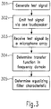
- a test signal is generated.
- different test signals are possible.
- binary white noise can be used as test signal. This is an advantageous choice since all frequencies are present and uniformly distributed.
- colored noise can also be used. For example, pink noise can be generated. As long as all frequencies are sufficiently activated, other colored noises can also be used.
- narrowband test signals such as band pass noise with variable center frequency. In this case, all frequency ranges should be activated successively.
- the test signal is emitted by one of the loudspeakers. This corresponds to the configuration of Fig. 2 . However, two or more loudspeakers can alternatively emit the test signal in parallel.
- the test signal is received by a microphone array, particularly by all microphone arrays.
- the signal emanating from the microphone array and having passed through the beamformer is fed to a signal processing means where the test signal and the received test signal are used to automatically determine a transfer function in the frequency domain in step 304.
- the transmission behavior can be determined in the time domain, for example, using an adaptive filter.
- the normalized least mean square (NLMS) algorithm with small increments can be adopted.
- the impulse response is to be transformed to the frequency domain to obtain the transfer function H ( e j ⁇ ).
- adaptive filters one can also use estimation methods based on periodograms or on autocorrelation or cross-correlation functions.
- the transfer function can be determined as the square root of the quotient of the short time power spectra ⁇ y 2 n / ⁇ x 2 n .
- Both short time power spectra are determined for each band pass noise so as to obtain sampling points at the center frequencies of the band pass signals.
- an equalizing filter characteristic is determined such that an equalizing filter for microphone array/loudspeaker pair is obtained resulting in a reduced feedback risk for this pair of components.
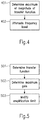
- Fig. 4 illustrates an example of how to determine (at least parts of) an equalizing filter characteristic in step 305 of Fig. 3 .
- This is particularly useful, when determining the transfer function using adaptive filters as described above.
- one or several maxima of the transfer function H ( e j ⁇ ) are determined in step 401, in other words, a maximum frequency ⁇ max
- ⁇ ⁇ ⁇ max max is determined.
- the number of frequencies determined in this way particularly depends on the design principle of the equalization filters. For example, 3 - 5 frequency values can be determined if these frequencies are sufficiently separated. If this is not the case, one can also determine more than 5 frequency values.
- the frequencies ⁇ max or the band pass ranges with the largest quotient are determined based on the above described short time power spectra.
- an attenuation is provided for one or several frequency bands (depending on the number of possible feedback frequencies) in step 402.
- attenuations are applied in small bands around the determined frequencies ⁇ max .
- attenuations of some dB can be inserted whereas the remaining frequency ranges are not attenuated.
- Corresponding steps can be performed for amplifying minima of the transfer function. In such a case, minimum frequencies are to be determined and corresponding amplifications are to be applied. In this way, an output signal is considered louder by the listener.
- Fig. 5 illustrates a modification of the maximum amplification (stability limit) of an indoor communication system after having determined the transfer function in step 501 as described above.
- This reciprocal value can be determined for each loudspeaker/microphone array pair.
- this stability limit can be individually determined for each vehicle (and each loudspeaker and microphone or microphone array mounted therein) and can be used to correct (increase) the maximum amplification as originally set by the manufacturer. In this way, the quality of indoor communication systems can further be improved.
- equalizing filters are used for reproducing signals of the indoor communication system, the equalizing filters should be placed before the mixing matrices of the audio amplifiers. In this case, the equalizing filters do not modify the sound of other audio sources of the vehicle.
- the previously described methods can also be used to improve the audio output of other audio components such as handsfree systems or speech recognition. If it is detected by the method that the so-called center loudspeaker being located at the vicinity of the front microphones creates larger microphone signals than the other loudspeakers, its output power can be reduced correspondingly. An overdriving of the microphones due to the audio output can be avoided in this way, which increases the performance of the handsfree system or the speech recognition system.
Claims (21)
- Verfahren zum automatischen Bestimmen einer Entzerrungsfiltereigenschaft für ein Innenraum-Nachrichtenübertragungssystem einer Fahrzeugkabine (100), wobei das Innenraum-Nachrichtenübertragungssystem mindestens einen Lautsprecher (103) und mindestens eine Mikrofonanordnung, die mit einer Strahlenbildungsvorrichtung (105; 105') verbunden ist, umfasst, wobei der mindestens eine Lautsprecher (103) der mindestens einen Mikrofonanordnung und einer entsprechenden Lautsprecherposition zugeordnet ist, die folgenden Schritte umfassend:a) Ausgeben eines vorbestimmten Testsignals durch einen Lautsprecher, insbesondere durch einen Lautsprecher des Innenraum-Nachrichtenübertragungssystems,b) Empfangen des Testsignals durch eine Mikrofonanordnung des Innenraum-Nachrichtenübertragungssystems und Strahlenbilden des Signals, das von der Mikrofonanordnung ausgeht, unter Verwendung der Strahlenbildungsvorrichtung, die damit verbunden ist, um ein empfangenes Testsignal zu erhalten,c) automatisches Bestimmen einer Übertragungsfunktion in dem Frequenzbereich auf Grundlage des Testsignals und des empfangenen Testsignals,dadurch gekennzeichnet, dass das Verfahren ferner die folgenden Schritte umfasst:d) automatisches Bestimmen einer Entzerrungsfiltereigenschaft auf Grundlage eines Bestimmens eines Extremwerts, insbesondere eines Maximalwerts des Betrags der Übertragungsfunktion; unde) automatisches Bestimmen eines maximalen Verstärkungswerts als

- Verfahren nach Anspruch 1, wobei Schritt a) das Ausgeben eines binären weißen Rauschens oder eines farbigen Rauschens, insbesondere eines rosa Rauschens, umfasst.
- Verfahren nach einem der vorhergehenden Ansprüche, wobei Schritt c) das Verarbeiten des Testsignals und des empfangenen Testsignals in dem Zeitbereich umfasst, insbesondere unter Verwendung eines adaptiven Filters oder unter Verwendung eines Schätzverfahrens auf Grundlage eines Periodogramms, einer Autokorrelationsfunktion oder einer Kreuzkorrelationsfunktion.
- Verfahren nach Anspruch 1, wobei Schritt a) das Ausgeben eines Bandpassrauschens mit variabler Mittelfrequenz umfasst.
- Verfahren nach Anspruch 4, wobei Schritt c) ein Bestimmen der Quadratwurzel des Quotienten des Kurzzeitleistungsspektrums des empfangenen Testsignals und des Kurzzeitleistungsspektrums des Testsignals für jedes Bandpassrauschen umfasst.
- Verfahren nach Anspruch 1, wobei Schritt d) ein Bestimmen eines globalen Extremwerts des Betrags der Übertragungsfunktion umfasst.
- Verfahren nach Anspruch 6, wobei Schritt d) ferner ein Bestimmen eines lokalen Extremwerts umfasst, bei dem sich der Betrag der Übertragungsfunktion nicht mehr als ein vorbestimmtes Maß von dem Betrag der Übertragungsfunktion an einem globalen Extremwert unterscheidet.
- Verfahren nach einem der Ansprüche 1 und 7, wobei Schritt d) ferner ein Bereitstellen einer Abschwächung eines vorbestimmten Frequenzbands, das an einem bestimmten Maximalwert zentriert ist, und/oder ein Bereitstellen einer Verstärkung eines vorbestimmen Frequenzbands, das an einem bestimmten Minimalwert zentriert ist, umfasst.
- Verfahren nach Anspruch 8, wobei eine Abschwächung unter Verwendung eines nichtlinearen Phasenfilters bereitgestellt ist.
- Verfahren zum automatischen Bestimmen eines maximalen Verstärkungswerts eines Innenraum-Nachrichtenübertragungssystems einer Fahrzeugkabine, Folgendes umfassend:
automatisches Bestimmen einer Entzerrungsfiltereigenschaft unter Verwendung des Verfahrens eines der Ansprüche 1-9 für einen vorbestimmten Lautsprecher. - Computerprogrammprodukt, das eines oder mehrere computerlesbare Medien umfasst, die computerlesbare Anweisungen zum Durchführen der Schritte des Verfahrens eines der vorhergehenden Ansprüche aufweisen.
- Innenraum-Nachrichtenübertragungssystem für eine Fahrzeugkabine (100), Folgendes umfassend:eine Signalerzeugungsvorrichtung, die dazu konfiguriert ist, ein vorbestimmtes Testsignal zu erzeugen,mindestens einen Lautsprecher (103), der mit der Signalerzeugungsvorrichtung zum Ausgeben eines vorbestimmten Testsignals verbunden ist,mindestens eine Mikrofonanordnung zum Empfangen des ausgegebenen Testsignals,eine Strahlenbildungsvorrichtung (105; 105') für jede Mikrofonanordnung zum Strahlenbilden des Signals, das von einer Mikrofonanordnung ausgeht, um ein empfangenes Testsignal bereitzustellen,ein Signalverarbeitungsmittel (104; 104'), das mit der Signalerzeugungsvorrichtung und mit der mindestens einen Mikrofonanordnung verbunden ist, wobei das Signalverarbeitungsmittel (104; 104') dazu konfiguriert ist, automatisch eine Übertragungsfunktion in dem Frequenzbereich auf Grundlage des Testsignals und des empfangenen Testsignals zu bestimmen, und automatisch eine Entzerrungsfiltereigenschaft auf Grundlage der Übertragungsfunktion zu bestimmen,wobei der mindestens eine Lautsprecher (103) der mindestens einen Mikrofonanordnung und einer entsprechenden Lautsprecherposition zugeordnet ist;dadurch gekennzeichnet, dass das Innenraum-Nachrichtenübertragungssystem ferner Folgendes umfasst:
wobei das Signalverarbeitungsmittel (104; 104') dazu konfiguriert ist, einen Extremwert, insbesondere einen Maximalwert, des Betrags der Übertragungsfunktion automatisch zu bestimmen und eine maximale Verstärkung automatisch als zu bestimmen, wobei H(e jΩ) die Übertragungsfunktion und G(e jΩ) die Frequenzantwort des Entzerrungsfilters ist.
 - Innenraum-Nachrichtenübertragungssystem nach Anspruch 12, das mindestens zwei Lautsprecher umfasst und wobei die Signalerzeugungsvorrichtung mit den mindestens zwei Lautsprechern derart verbunden ist, dass das Testsignal von jedem Lautsprecher separat ausgegeben werden kann.
- Innenraum-Nachrichtenübertragungssystem nach einem der Ansprüche 12-13, wobei die Signalerzeugungsvorrichtung dazu konfiguriert ist, ein binäres weißes Rauschen oder ein farbiges Rauschen, insbesondere ein rosa Rauschen, auszugeben.
- Innenraum-Nachrichtenübertragungssystem nach einem der Ansprüche 12-14, wobei das Signalverarbeitungsmittel dazu konfiguriert ist, das Testsignal und das empfangene Testsignal in dem Zeitbereich zu verarbeiten, insbesondere unter Verwendung eines adaptiven Filters oder unter Verwendung eines Schätzverfahrens auf Grundlage eines Periodogramms, einer Autorkorrelationsfunktion oder einer Kreuzkorrelationsfunktion.
- Innenraum-Nachrichtenübertragungssystem nach einem der Ansprüche 12-15, wobei die Signalerzeugungsvorrichtung dazu konfiguriert ist, ein Bandpassrauschen mit variabler Mittelfrequenz auszugeben.
- Innenraum-Nachrichtenübertragungssystem nach Anspruch 16, wobei das Signalverarbeitungsmittel dazu konfiguriert ist, die Quadratwurzel des Quotienten des Kurzzeitleistungsspektrums des empfangenen Testsignals und das Kurzzeitleistungsspektrum des Testsignals für jedes Bandpassrauschen zu bestimmen.
- Innenraum-Nachrichtenübertragungssystem nach einem der Ansprüche 12, wobei das Signalverarbeitungsmittel dazu konfiguriert ist, einen globalen Extremwert des Betrags der Übertragungsfunktion zu bestimmen.
- Innenraum-Nachrichtenübertragungssystemnach Anspruch 18, wobei das Signalverarbeitungsmittel dazu konfiguriert ist, ferner einen lokalen Extremwert zu bestimmen, bei dem sich der Betrag der Übertragungsfunktion nicht mehr als ein vorbestimmtes Maß von dem Betrag der Übertragungsfunktion an einem globalen Extremwert unterscheidet.
- Innenraum-Nachrichtenübertragungssystem nach einem der Ansprüche 12-19, wobei das Signalverarbeitungsmittel dazu konfiguriert ist, ein vorbestimmtes Frequenzband, das an einem bestimmen Maximalwert zentriert ist, abzuschwächen und/oder ein vorbestimmtes Frequenzband, das an einem bestimmten Minimalwert zentriert ist, zu verstärken.
- Innenraum-Nachrichtenübertragungssystem nach Anspruch 20, wobei das Signalverarbeitungsmittel einen nichtlinearen Phasenfilter zum Abschwächen eines vorbestimmten Frequenzbands umfasst.
Priority Applications (4)
| Application Number | Priority Date | Filing Date | Title |
|---|---|---|---|
| EP04010231.1A EP1591995B1 (de) | 2004-04-29 | 2004-04-29 | Innenraum-Nachrichtübertragungssystem für eine Fahrzeugkabine |
| JP2005133496A JP2005318636A (ja) | 2004-04-29 | 2005-04-28 | 車両用キャビンのための屋内通信システム |
| US11/118,092 US8081776B2 (en) | 2004-04-29 | 2005-04-29 | Indoor communication system for a vehicular cabin |
| JP2011131638A JP5694063B2 (ja) | 2004-04-29 | 2011-06-13 | 車両用キャビンのための屋内通信システム |
Applications Claiming Priority (1)
| Application Number | Priority Date | Filing Date | Title |
|---|---|---|---|
| EP04010231.1A EP1591995B1 (de) | 2004-04-29 | 2004-04-29 | Innenraum-Nachrichtübertragungssystem für eine Fahrzeugkabine |
Publications (2)
| Publication Number | Publication Date |
|---|---|
| EP1591995A1 EP1591995A1 (de) | 2005-11-02 |
| EP1591995B1 true EP1591995B1 (de) | 2019-06-19 |
Family
ID=34924788
Family Applications (1)
| Application Number | Title | Priority Date | Filing Date |
|---|---|---|---|
| EP04010231.1A Expired - Lifetime EP1591995B1 (de) | 2004-04-29 | 2004-04-29 | Innenraum-Nachrichtübertragungssystem für eine Fahrzeugkabine |
Country Status (3)
| Country | Link |
|---|---|
| US (1) | US8081776B2 (de) |
| EP (1) | EP1591995B1 (de) |
| JP (2) | JP2005318636A (de) |
Cited By (1)
| Publication number | Priority date | Publication date | Assignee | Title |
|---|---|---|---|---|
| WO2024008503A1 (de) * | 2022-07-08 | 2024-01-11 | Mercedes-Benz Group AG | Verfahren zur richtungskalibrierung von an einem fahrzeug angeordneten mikrofonen |
Families Citing this family (45)
| Publication number | Priority date | Publication date | Assignee | Title |
|---|---|---|---|---|
| US20110311065A1 (en) * | 2006-03-14 | 2011-12-22 | Harman International Industries, Incorporated | Extraction of channels from multichannel signals utilizing stimulus |
| EP1858295B1 (de) * | 2006-05-19 | 2013-06-26 | Nuance Communications, Inc. | Entzerrung zur Anwendung von akustischen Signalen |
| EP1860911A1 (de) * | 2006-05-24 | 2007-11-28 | Harman/Becker Automotive Systems GmbH | System und Verfahren zur Verbesserung der Kommunikation in einem Raum |
| US8214219B2 (en) * | 2006-09-15 | 2012-07-03 | Volkswagen Of America, Inc. | Speech communications system for a vehicle and method of operating a speech communications system for a vehicle |
| DE102007014816B4 (de) | 2007-03-28 | 2023-05-17 | Iav Gmbh Ingenieurgesellschaft Auto Und Verkehr | Kommunikationssystem und Verfahren zum Betreiben eines Kommunikationssystems in einem Fahrzeug |
| WO2008122930A1 (en) * | 2007-04-04 | 2008-10-16 | Koninklijke Philips Electronics N.V. | Sound enhancement in closed spaces |
| US8411847B2 (en) * | 2008-06-10 | 2013-04-02 | Conexant Systems, Inc. | Acoustic echo canceller |
| WO2010138311A1 (en) * | 2009-05-26 | 2010-12-02 | Dolby Laboratories Licensing Corporation | Equalization profiles for dynamic equalization of audio data |
| WO2010138309A1 (en) | 2009-05-26 | 2010-12-02 | Dolby Laboratories Licensing Corporation | Audio signal dynamic equalization processing control |
| JP5290949B2 (ja) * | 2009-12-17 | 2013-09-18 | キヤノン株式会社 | 音響処理装置及び方法 |
| EP2416593A1 (de) * | 2010-08-02 | 2012-02-08 | Svox AG | Verfahren zur Innenraumkommunikation |
| EP2490459B1 (de) | 2011-02-18 | 2018-04-11 | Svox AG | Verfahren zur Sprachsignalmischung |
| EP2530835B1 (de) * | 2011-05-30 | 2015-07-22 | Harman Becker Automotive Systems GmbH | Automatische Einstellung eines geschwindigkeitsabhängigen Enzerrungssteuerungssystems |
| CN105472525B (zh) | 2011-07-01 | 2018-11-13 | 杜比实验室特许公司 | 音频回放系统监视 |
| US9641934B2 (en) * | 2012-01-10 | 2017-05-02 | Nuance Communications, Inc. | In-car communication system for multiple acoustic zones |
| CN103428607A (zh) * | 2012-05-25 | 2013-12-04 | 华为技术有限公司 | 一种音频信号播放系统及电子设备 |
| US9502050B2 (en) | 2012-06-10 | 2016-11-22 | Nuance Communications, Inc. | Noise dependent signal processing for in-car communication systems with multiple acoustic zones |
| EP2859772B1 (de) | 2012-06-10 | 2018-12-19 | Nuance Communications, Inc. | Windgeräuscherkennung für wageninstallierte kommunikationssysteme mit mehreren akustischen zonen |
| US9805738B2 (en) | 2012-09-04 | 2017-10-31 | Nuance Communications, Inc. | Formant dependent speech signal enhancement |
| WO2014070139A2 (en) | 2012-10-30 | 2014-05-08 | Nuance Communications, Inc. | Speech enhancement |
| BR112016028450B1 (pt) * | 2014-06-03 | 2022-01-11 | Intel Corporation | Método para a determinação de correções para uma pluralidade de microfones em teste |
| US9947334B2 (en) * | 2014-12-12 | 2018-04-17 | Qualcomm Incorporated | Enhanced conversational communications in shared acoustic space |
| US9672805B2 (en) | 2014-12-12 | 2017-06-06 | Qualcomm Incorporated | Feedback cancelation for enhanced conversational communications in shared acoustic space |
| US9743213B2 (en) * | 2014-12-12 | 2017-08-22 | Qualcomm Incorporated | Enhanced auditory experience in shared acoustic space |
| US10194260B2 (en) | 2015-02-27 | 2019-01-29 | Pioneer Corporation | Sound volume control device, sound volume control method and sound volume control program |
| US10091581B2 (en) * | 2015-07-30 | 2018-10-02 | Roku, Inc. | Audio preferences for media content players |
| EP3133831A1 (de) * | 2015-08-20 | 2017-02-22 | Harman Becker Automotive Systems GmbH | System und methode für kommunikation im auto |
| CN105280195B (zh) | 2015-11-04 | 2018-12-28 | 腾讯科技(深圳)有限公司 | 语音信号的处理方法及装置 |
| EP3171613A1 (de) * | 2015-11-20 | 2017-05-24 | Harman Becker Automotive Systems GmbH | Tonverstärkung |
| US11348595B2 (en) * | 2017-01-04 | 2022-05-31 | Blackberry Limited | Voice interface and vocal entertainment system |
| US10110997B2 (en) | 2017-02-17 | 2018-10-23 | 2236008 Ontario, Inc. | System and method for feedback control for in-car communications |
| EP3370438B1 (de) * | 2017-03-02 | 2019-09-04 | Vestel Elektronik Sanayi ve Ticaret A.S. | Lautsprecherprüfung und schutz |
| JP6873549B2 (ja) * | 2017-03-28 | 2021-05-19 | 株式会社ディーアンドエムホールディングス | オーディオ装置およびコンピュータで読み取り可能なプログラム |
| US10433086B1 (en) * | 2018-06-25 | 2019-10-01 | Biamp Systems, LLC | Microphone array with automated adaptive beam tracking |
| US10210882B1 (en) | 2018-06-25 | 2019-02-19 | Biamp Systems, LLC | Microphone array with automated adaptive beam tracking |
| US10694285B2 (en) | 2018-06-25 | 2020-06-23 | Biamp Systems, LLC | Microphone array with automated adaptive beam tracking |
| EP3813384B1 (de) * | 2018-08-02 | 2023-09-06 | Nippon Telegraph And Telephone Corporation | Klangerfassungs-/lautsprechervorrichtung, verfahren dafür und programm |
| FR3087076B1 (fr) * | 2018-10-08 | 2022-02-25 | Arkamys | Procede et dispositif de controle de la distorsion d’un systeme de haut-parleurs embarque dans un vehicule |
| US11211061B2 (en) | 2019-01-07 | 2021-12-28 | 2236008 Ontario Inc. | Voice control in a multi-talker and multimedia environment |
| US10857909B2 (en) | 2019-02-05 | 2020-12-08 | Lear Corporation | Electrical assembly |
| US11729550B2 (en) * | 2019-05-21 | 2023-08-15 | Nippon Telegraph And Telephone Corporation | Echo cancelation method, apparatus, program and recording medium |
| JP7286532B2 (ja) | 2019-12-27 | 2023-06-05 | フォルシアクラリオン・エレクトロニクス株式会社 | 信号処理装置、音響装置、信号処理方法及び信号処理プログラム |
| US20230078170A1 (en) * | 2019-12-30 | 2023-03-16 | Harman Becker Automotive Systems Gmbh | Method for performing acoustic measurements |
| WO2021226628A2 (en) | 2020-05-04 | 2021-11-11 | Shure Acquisition Holdings, Inc. | Intelligent audio system using multiple sensor modalities |
| US11297452B2 (en) * | 2020-08-14 | 2022-04-05 | Subaru Corporation | Inspection system and inspection method |
Citations (4)
| Publication number | Priority date | Publication date | Assignee | Title |
|---|---|---|---|---|
| US5170433A (en) * | 1986-10-07 | 1992-12-08 | Adaptive Control Limited | Active vibration control |
| EP1077584A2 (de) * | 1999-08-16 | 2001-02-21 | DaimlerChrysler AG | Verfahren und Vorrichtung zur Kompensation von Verlusten eines Signals |
| WO2003010996A2 (en) * | 2001-07-20 | 2003-02-06 | Koninklijke Philips Electronics N.V. | Sound reinforcement system having an echo suppressor and loudspeaker beamformer |
| US6674865B1 (en) * | 2000-10-19 | 2004-01-06 | Lear Corporation | Automatic volume control for communication system |
Family Cites Families (28)
| Publication number | Priority date | Publication date | Assignee | Title |
|---|---|---|---|---|
| NL8300671A (nl) * | 1983-02-23 | 1984-09-17 | Philips Nv | Automatisch egalisatiesysteem met dtf of fft. |
| US4739513A (en) * | 1984-05-31 | 1988-04-19 | Pioneer Electronic Corporation | Method and apparatus for measuring and correcting acoustic characteristic in sound field |
| EP0304257A3 (de) | 1987-08-19 | 1989-09-27 | McGregor, Thomas | Sprachverstärkungseinrichtung |
| JP2938076B2 (ja) * | 1988-02-23 | 1999-08-23 | 株式会社東芝 | エコーキャンセラー装置 |
| GB9026906D0 (en) * | 1990-12-11 | 1991-01-30 | B & W Loudspeakers | Compensating filters |
| JP2604510B2 (ja) * | 1991-09-26 | 1997-04-30 | 富士通テン株式会社 | 自動音響周波数特性補正装置 |
| JP2940585B2 (ja) * | 1992-11-16 | 1999-08-25 | 株式会社ケンウッド | 伝送周波数特性補正装置 |
| US5386478A (en) * | 1993-09-07 | 1995-01-31 | Harman International Industries, Inc. | Sound system remote control with acoustic sensor |
| JP3235925B2 (ja) * | 1993-11-19 | 2001-12-04 | 松下電器産業株式会社 | ハウリング抑制装置 |
| JP3336729B2 (ja) * | 1994-02-28 | 2002-10-21 | ヤマハ株式会社 | 音場制御装置 |
| US6108237A (en) | 1997-07-17 | 2000-08-22 | Micron Technology, Inc. | Fast-sensing amplifier for flash memory |
| WO1996032776A2 (en) * | 1995-04-03 | 1996-10-17 | Philips Electronics N.V. | Signal amplification system with automatic equalizer |
| JPH09247787A (ja) * | 1996-03-04 | 1997-09-19 | Matsushita Electric Ind Co Ltd | 音場制御システム |
| US5796819A (en) * | 1996-07-24 | 1998-08-18 | Ericsson Inc. | Echo canceller for non-linear circuits |
| US6408079B1 (en) * | 1996-10-23 | 2002-06-18 | Matsushita Electric Industrial Co., Ltd. | Distortion removal apparatus, method for determining coefficient for the same, and processing speaker system, multi-processor, and amplifier including the same |
| US6496581B1 (en) | 1997-09-11 | 2002-12-17 | Digisonix, Inc. | Coupled acoustic echo cancellation system |
| JP4186307B2 (ja) * | 1999-04-30 | 2008-11-26 | ヤマハ株式会社 | ハウリング防止装置 |
| JP3751795B2 (ja) | 1999-11-22 | 2006-03-01 | 株式会社東芝 | 歩行者用道案内文自動作成装置および方法並びに記録媒体 |
| AU2001255525A1 (en) * | 2000-04-21 | 2001-11-07 | Keyhold Engineering, Inc. | Self-calibrating surround sound system |
| JP2001346299A (ja) * | 2000-05-31 | 2001-12-14 | Sony Corp | 音場補正方法及びオーディオ装置 |
| FR2820227B1 (fr) * | 2001-01-30 | 2003-04-18 | France Telecom | Procede et dispositif de reduction de bruit |
| US6665411B2 (en) | 2001-02-21 | 2003-12-16 | Digisonix Llc | DVE system with instability detection |
| JP4482247B2 (ja) * | 2001-04-26 | 2010-06-16 | パナソニック株式会社 | 自動音質音量調整音響システムおよびその音質音量調整方法 |
| JP3727258B2 (ja) | 2001-08-13 | 2005-12-14 | 富士通株式会社 | エコー抑制処理システム |
| US20040114771A1 (en) * | 2002-12-12 | 2004-06-17 | Mitchell Vaughan | Multimedia system with pre-stored equalization sets for multiple vehicle environments |
| US7653203B2 (en) * | 2004-01-13 | 2010-01-26 | Bose Corporation | Vehicle audio system surround modes |
| JP4856987B2 (ja) | 2006-03-09 | 2012-01-18 | 株式会社エンプラス | 撮像レンズ |
| JP4819081B2 (ja) | 2008-04-10 | 2011-11-16 | 株式会社三共 | 遊技機 |
-
2004
- 2004-04-29 EP EP04010231.1A patent/EP1591995B1/de not_active Expired - Lifetime
-
2005
- 2005-04-28 JP JP2005133496A patent/JP2005318636A/ja active Pending
- 2005-04-29 US US11/118,092 patent/US8081776B2/en active Active
-
2011
- 2011-06-13 JP JP2011131638A patent/JP5694063B2/ja active Active
Patent Citations (4)
| Publication number | Priority date | Publication date | Assignee | Title |
|---|---|---|---|---|
| US5170433A (en) * | 1986-10-07 | 1992-12-08 | Adaptive Control Limited | Active vibration control |
| EP1077584A2 (de) * | 1999-08-16 | 2001-02-21 | DaimlerChrysler AG | Verfahren und Vorrichtung zur Kompensation von Verlusten eines Signals |
| US6674865B1 (en) * | 2000-10-19 | 2004-01-06 | Lear Corporation | Automatic volume control for communication system |
| WO2003010996A2 (en) * | 2001-07-20 | 2003-02-06 | Koninklijke Philips Electronics N.V. | Sound reinforcement system having an echo suppressor and loudspeaker beamformer |
Cited By (1)
| Publication number | Priority date | Publication date | Assignee | Title |
|---|---|---|---|---|
| WO2024008503A1 (de) * | 2022-07-08 | 2024-01-11 | Mercedes-Benz Group AG | Verfahren zur richtungskalibrierung von an einem fahrzeug angeordneten mikrofonen |
Also Published As
| Publication number | Publication date |
|---|---|
| EP1591995A1 (de) | 2005-11-02 |
| JP2011205692A (ja) | 2011-10-13 |
| US8081776B2 (en) | 2011-12-20 |
| JP5694063B2 (ja) | 2015-04-01 |
| US20050265560A1 (en) | 2005-12-01 |
| JP2005318636A (ja) | 2005-11-10 |
Similar Documents
| Publication | Publication Date | Title |
|---|---|---|
| EP1591995B1 (de) | Innenraum-Nachrichtübertragungssystem für eine Fahrzeugkabine | |
| US9002028B2 (en) | Noisy environment communication enhancement system | |
| US7643641B2 (en) | System for communication enhancement in a noisy environment | |
| EP3040984B1 (de) | Schallzonenanordnung mit zonenweiser sprachunterdrückung | |
| US8306234B2 (en) | System for improving communication in a room | |
| US6674865B1 (en) | Automatic volume control for communication system | |
| US7171003B1 (en) | Robust and reliable acoustic echo and noise cancellation system for cabin communication | |
| US7117145B1 (en) | Adaptive filter for speech enhancement in a noisy environment | |
| EP1429315B1 (de) | Verfahren und system zum unterdrücken von echos und geräuschen in umgebungen unter variablen akustischen und stark rückgekoppelten bedingungen | |
| US7039197B1 (en) | User interface for communication system | |
| CN100446530C (zh) | 校准波束形成器的方法和消除回声的方法 | |
| CA2628524C (en) | Sound tuning method | |
| EP1879181B1 (de) | Verfahren zur Kompensation von Audiosignalkomponenten in einem Fahrzeugkommunikationssystem und Vorrichtung dafür | |
| EP1718103B1 (de) | Kompensation des Echos und der Rückkopplung | |
| Schmidt et al. | Signal processing for in-car communication systems | |
| EP1858295B1 (de) | Entzerrung zur Anwendung von akustischen Signalen | |
| CN108550370B (zh) | 用于车内通信的反馈控制的系统和方法 | |
| KR20040019339A (ko) | 반향 억제기 및 확성기 빔 형성기를 구비한 사운드 보강시스템 | |
| WO2002032356A1 (en) | Transient processing for communication system | |
| EP2490218B1 (de) | Verfahren zur Interferenzunterdrückung | |
| EP1623600B1 (de) | Verfahren und system zur kommunikationsverbesserung in einer rauschenden umgebung | |
| Schmidt | Applications of acoustic echo control-an overview | |
| JP5383008B2 (ja) | 音声明瞭度改善システム及び音声明瞭度改善方法 | |
| Linhard et al. | Passenger in-car communication enhancement | |
| Freudenberger et al. | Noise and feedback suppression for in-car communication systems |
Legal Events
| Date | Code | Title | Description |
|---|---|---|---|
| PUAI | Public reference made under article 153(3) epc to a published international application that has entered the european phase |
Free format text: ORIGINAL CODE: 0009012 |
|
| AK | Designated contracting states |
Kind code of ref document: A1 Designated state(s): AT BE BG CH CY CZ DE DK EE ES FI FR GB GR HU IE IT LI LU MC NL PL PT RO SE SI SK TR |
|
| AX | Request for extension of the european patent |
Extension state: AL HR LT LV MK |
|
| 17P | Request for examination filed |
Effective date: 20060502 |
|
| AKX | Designation fees paid |
Designated state(s): AT BE BG CH CY CZ DE DK EE ES FI FR GB GR HU IE IT LI LU MC NL PL PT RO SE SI SK TR |
|
| 17Q | First examination report despatched |
Effective date: 20060630 |
|
| STAA | Information on the status of an ep patent application or granted ep patent |
Free format text: STATUS: EXAMINATION IS IN PROGRESS |
|
| GRAP | Despatch of communication of intention to grant a patent |
Free format text: ORIGINAL CODE: EPIDOSNIGR1 |
|
| STAA | Information on the status of an ep patent application or granted ep patent |
Free format text: STATUS: GRANT OF PATENT IS INTENDED |
|
| INTG | Intention to grant announced |
Effective date: 20190104 |
|
| GRAS | Grant fee paid |
Free format text: ORIGINAL CODE: EPIDOSNIGR3 |
|
| GRAA | (expected) grant |
Free format text: ORIGINAL CODE: 0009210 |
|
| STAA | Information on the status of an ep patent application or granted ep patent |
Free format text: STATUS: THE PATENT HAS BEEN GRANTED |
|
| AK | Designated contracting states |
Kind code of ref document: B1 Designated state(s): AT BE BG CH CY CZ DE DK EE ES FI FR GB GR HU IE IT LI LU MC NL PL PT RO SE SI SK TR |
|
| REG | Reference to a national code |
Ref country code: GB Ref legal event code: FG4D |
|
| REG | Reference to a national code |
Ref country code: CH Ref legal event code: EP |
|
| REG | Reference to a national code |
Ref country code: IE Ref legal event code: FG4D |
|
| REG | Reference to a national code |
Ref country code: DE Ref legal event code: R096 Ref document number: 602004054057 Country of ref document: DE |
|
| REG | Reference to a national code |
Ref country code: AT Ref legal event code: REF Ref document number: 1146501 Country of ref document: AT Kind code of ref document: T Effective date: 20190715 |
|
| REG | Reference to a national code |
Ref country code: NL Ref legal event code: MP Effective date: 20190619 |
|
| PG25 | Lapsed in a contracting state [announced via postgrant information from national office to epo] |
Ref country code: FI Free format text: LAPSE BECAUSE OF FAILURE TO SUBMIT A TRANSLATION OF THE DESCRIPTION OR TO PAY THE FEE WITHIN THE PRESCRIBED TIME-LIMIT Effective date: 20190619 Ref country code: SE Free format text: LAPSE BECAUSE OF FAILURE TO SUBMIT A TRANSLATION OF THE DESCRIPTION OR TO PAY THE FEE WITHIN THE PRESCRIBED TIME-LIMIT Effective date: 20190619 |
|
| PG25 | Lapsed in a contracting state [announced via postgrant information from national office to epo] |
Ref country code: GR Free format text: LAPSE BECAUSE OF FAILURE TO SUBMIT A TRANSLATION OF THE DESCRIPTION OR TO PAY THE FEE WITHIN THE PRESCRIBED TIME-LIMIT Effective date: 20190920 Ref country code: BG Free format text: LAPSE BECAUSE OF FAILURE TO SUBMIT A TRANSLATION OF THE DESCRIPTION OR TO PAY THE FEE WITHIN THE PRESCRIBED TIME-LIMIT Effective date: 20190919 |
|
| REG | Reference to a national code |
Ref country code: AT Ref legal event code: MK05 Ref document number: 1146501 Country of ref document: AT Kind code of ref document: T Effective date: 20190619 |
|
| PG25 | Lapsed in a contracting state [announced via postgrant information from national office to epo] |
Ref country code: SK Free format text: LAPSE BECAUSE OF FAILURE TO SUBMIT A TRANSLATION OF THE DESCRIPTION OR TO PAY THE FEE WITHIN THE PRESCRIBED TIME-LIMIT Effective date: 20190619 Ref country code: EE Free format text: LAPSE BECAUSE OF FAILURE TO SUBMIT A TRANSLATION OF THE DESCRIPTION OR TO PAY THE FEE WITHIN THE PRESCRIBED TIME-LIMIT Effective date: 20190619 Ref country code: PT Free format text: LAPSE BECAUSE OF FAILURE TO SUBMIT A TRANSLATION OF THE DESCRIPTION OR TO PAY THE FEE WITHIN THE PRESCRIBED TIME-LIMIT Effective date: 20191021 Ref country code: AT Free format text: LAPSE BECAUSE OF FAILURE TO SUBMIT A TRANSLATION OF THE DESCRIPTION OR TO PAY THE FEE WITHIN THE PRESCRIBED TIME-LIMIT Effective date: 20190619 Ref country code: RO Free format text: LAPSE BECAUSE OF FAILURE TO SUBMIT A TRANSLATION OF THE DESCRIPTION OR TO PAY THE FEE WITHIN THE PRESCRIBED TIME-LIMIT Effective date: 20190619 Ref country code: CZ Free format text: LAPSE BECAUSE OF FAILURE TO SUBMIT A TRANSLATION OF THE DESCRIPTION OR TO PAY THE FEE WITHIN THE PRESCRIBED TIME-LIMIT Effective date: 20190619 Ref country code: NL Free format text: LAPSE BECAUSE OF FAILURE TO SUBMIT A TRANSLATION OF THE DESCRIPTION OR TO PAY THE FEE WITHIN THE PRESCRIBED TIME-LIMIT Effective date: 20190619 |
|
| PG25 | Lapsed in a contracting state [announced via postgrant information from national office to epo] |
Ref country code: ES Free format text: LAPSE BECAUSE OF FAILURE TO SUBMIT A TRANSLATION OF THE DESCRIPTION OR TO PAY THE FEE WITHIN THE PRESCRIBED TIME-LIMIT Effective date: 20190619 Ref country code: IT Free format text: LAPSE BECAUSE OF FAILURE TO SUBMIT A TRANSLATION OF THE DESCRIPTION OR TO PAY THE FEE WITHIN THE PRESCRIBED TIME-LIMIT Effective date: 20190619 |
|
| PG25 | Lapsed in a contracting state [announced via postgrant information from national office to epo] |
Ref country code: TR Free format text: LAPSE BECAUSE OF FAILURE TO SUBMIT A TRANSLATION OF THE DESCRIPTION OR TO PAY THE FEE WITHIN THE PRESCRIBED TIME-LIMIT Effective date: 20190619 |
|
| PG25 | Lapsed in a contracting state [announced via postgrant information from national office to epo] |
Ref country code: PL Free format text: LAPSE BECAUSE OF FAILURE TO SUBMIT A TRANSLATION OF THE DESCRIPTION OR TO PAY THE FEE WITHIN THE PRESCRIBED TIME-LIMIT Effective date: 20190619 Ref country code: DK Free format text: LAPSE BECAUSE OF FAILURE TO SUBMIT A TRANSLATION OF THE DESCRIPTION OR TO PAY THE FEE WITHIN THE PRESCRIBED TIME-LIMIT Effective date: 20190619 |
|
| REG | Reference to a national code |
Ref country code: DE Ref legal event code: R097 Ref document number: 602004054057 Country of ref document: DE |
|
| PLBE | No opposition filed within time limit |
Free format text: ORIGINAL CODE: 0009261 |
|
| STAA | Information on the status of an ep patent application or granted ep patent |
Free format text: STATUS: NO OPPOSITION FILED WITHIN TIME LIMIT |
|
| 26N | No opposition filed |
Effective date: 20200603 |
|
| PG25 | Lapsed in a contracting state [announced via postgrant information from national office to epo] |
Ref country code: SI Free format text: LAPSE BECAUSE OF FAILURE TO SUBMIT A TRANSLATION OF THE DESCRIPTION OR TO PAY THE FEE WITHIN THE PRESCRIBED TIME-LIMIT Effective date: 20190619 |
|
| PG25 | Lapsed in a contracting state [announced via postgrant information from national office to epo] |
Ref country code: MC Free format text: LAPSE BECAUSE OF FAILURE TO SUBMIT A TRANSLATION OF THE DESCRIPTION OR TO PAY THE FEE WITHIN THE PRESCRIBED TIME-LIMIT Effective date: 20190619 |
|
| REG | Reference to a national code |
Ref country code: CH Ref legal event code: PL |
|
| PG25 | Lapsed in a contracting state [announced via postgrant information from national office to epo] |
Ref country code: LI Free format text: LAPSE BECAUSE OF NON-PAYMENT OF DUE FEES Effective date: 20200430 Ref country code: FR Free format text: LAPSE BECAUSE OF NON-PAYMENT OF DUE FEES Effective date: 20200430 Ref country code: LU Free format text: LAPSE BECAUSE OF NON-PAYMENT OF DUE FEES Effective date: 20200429 Ref country code: CH Free format text: LAPSE BECAUSE OF NON-PAYMENT OF DUE FEES Effective date: 20200430 |
|
| REG | Reference to a national code |
Ref country code: BE Ref legal event code: MM Effective date: 20200430 |
|
| PG25 | Lapsed in a contracting state [announced via postgrant information from national office to epo] |
Ref country code: BE Free format text: LAPSE BECAUSE OF NON-PAYMENT OF DUE FEES Effective date: 20200430 |
|
| PG25 | Lapsed in a contracting state [announced via postgrant information from national office to epo] |
Ref country code: IE Free format text: LAPSE BECAUSE OF NON-PAYMENT OF DUE FEES Effective date: 20200429 |
|
| PG25 | Lapsed in a contracting state [announced via postgrant information from national office to epo] |
Ref country code: CY Free format text: LAPSE BECAUSE OF FAILURE TO SUBMIT A TRANSLATION OF THE DESCRIPTION OR TO PAY THE FEE WITHIN THE PRESCRIBED TIME-LIMIT Effective date: 20190619 |
|
| PGFP | Annual fee paid to national office [announced via postgrant information from national office to epo] |
Ref country code: GB Payment date: 20230321 Year of fee payment: 20 |
|
| P01 | Opt-out of the competence of the unified patent court (upc) registered |
Effective date: 20230526 |
|
| PGFP | Annual fee paid to national office [announced via postgrant information from national office to epo] |
Ref country code: DE Payment date: 20230321 Year of fee payment: 20 |