EP1591983A2 - Elektromagnetisches Antriebssystem für Anzeigepixeln - Google Patents
Elektromagnetisches Antriebssystem für Anzeigepixeln Download PDFInfo
- Publication number
- EP1591983A2 EP1591983A2 EP05007967A EP05007967A EP1591983A2 EP 1591983 A2 EP1591983 A2 EP 1591983A2 EP 05007967 A EP05007967 A EP 05007967A EP 05007967 A EP05007967 A EP 05007967A EP 1591983 A2 EP1591983 A2 EP 1591983A2
- Authority
- EP
- European Patent Office
- Prior art keywords
- flap
- magnetic
- display pixel
- switching
- magnetic system
- Prior art date
- Legal status (The legal status is an assumption and is not a legal conclusion. Google has not performed a legal analysis and makes no representation as to the accuracy of the status listed.)
- Withdrawn
Links
- 238000001746 injection moulding Methods 0.000 claims abstract description 7
- 230000003993 interaction Effects 0.000 claims abstract description 6
- 229920003023 plastic Polymers 0.000 claims description 29
- 239000004033 plastic Substances 0.000 claims description 29
- 238000004519 manufacturing process Methods 0.000 claims description 16
- 239000000463 material Substances 0.000 claims description 15
- 238000000034 method Methods 0.000 claims description 14
- 230000008569 process Effects 0.000 claims description 13
- 238000000465 moulding Methods 0.000 claims description 9
- 229910000859 α-Fe Inorganic materials 0.000 claims description 9
- 229910001172 neodymium magnet Inorganic materials 0.000 claims description 7
- 239000000696 magnetic material Substances 0.000 claims description 5
- 229910052761 rare earth metal Inorganic materials 0.000 claims description 3
- 150000002910 rare earth metals Chemical class 0.000 claims description 3
- 230000005415 magnetization Effects 0.000 abstract description 13
- 239000000243 solution Substances 0.000 abstract description 13
- 238000010276 construction Methods 0.000 description 6
- 238000005094 computer simulation Methods 0.000 description 4
- 239000003973 paint Substances 0.000 description 3
- 238000004804 winding Methods 0.000 description 3
- 230000008901 benefit Effects 0.000 description 2
- 239000003086 colorant Substances 0.000 description 2
- 239000000470 constituent Substances 0.000 description 2
- 230000004907 flux Effects 0.000 description 2
- 239000011159 matrix material Substances 0.000 description 2
- 238000004801 process automation Methods 0.000 description 2
- 125000006850 spacer group Chemical group 0.000 description 2
- 238000007669 thermal treatment Methods 0.000 description 2
- 238000005265 energy consumption Methods 0.000 description 1
- 230000009467 reduction Effects 0.000 description 1
- 230000035939 shock Effects 0.000 description 1
- 238000005476 soldering Methods 0.000 description 1
Images

Classifications
-
- G—PHYSICS
- G09—EDUCATION; CRYPTOGRAPHY; DISPLAY; ADVERTISING; SEALS
- G09F—DISPLAYING; ADVERTISING; SIGNS; LABELS OR NAME-PLATES; SEALS
- G09F9/00—Indicating arrangements for variable information in which the information is built-up on a support by selection or combination of individual elements
- G09F9/30—Indicating arrangements for variable information in which the information is built-up on a support by selection or combination of individual elements in which the desired character or characters are formed by combining individual elements
- G09F9/37—Indicating arrangements for variable information in which the information is built-up on a support by selection or combination of individual elements in which the desired character or characters are formed by combining individual elements being movable elements
- G09F9/375—Indicating arrangements for variable information in which the information is built-up on a support by selection or combination of individual elements in which the desired character or characters are formed by combining individual elements being movable elements the position of the elements being controlled by the application of a magnetic field
Definitions
- Objective of the invention is a construction, materials and process of manufacturing of the magnetic circuit of the display pixel in electromagnetic display panel, which actuates the rotation of the display pixel flap.
- Present invention is classified in the group of bistable magnetic actuators, which are based on interaction of the magnetic field of a permanent magnet built in display pixel flap and the magnetic field of the core of an electromagnet.
- the patent application is classified in groups H01F 3/14, H01F 7/14 and H01F 7/121, its use is classified in groups G09F 3/4 and G09F 9/37.
- the technical problem solved by the present invention is to provide a novel, simple, compact and low production cost construction, of a display pixel electro magnetic driving system.
- This electro magnetic system is actually a bistable actuator, which has to switch the display pixel from a first bistable position into a second bistable position (and reverse) with minimum power consumption. Therefore the magnetic circuit must be specially designed including materials with special magnetic properties. Besides this the design of the magnetic circuit has to be optimized to allow for the reduction of the magnetic interaction between neighbouring display pixels as much as possible. The system must work in wide temperature range and has to guarantee the stability of both bistable positions of the display pixel flap. If the external forces resulting from mechanical stress, shock, vibrations or similar would result in changing the position of the display pixel flap, the remanent magnetic forces on the display pixel flap should be sufficient to restore the required position immediately after the external forces disappear.
- the electromagnetic display panels have been known for over two decades and are playing an important role in niche applications, where relatively large size, medium information content display panels, with high contrast and excellent visibility in rather high ambient lighting conditions are required.
- the bistable electromagnetic display panels (US 3,871,945, US 4,577,427, US 4,860,470, EP 0 084 959, EP 0 731 435 A1, US 4,243,978, US 5,771,616, US 6,272,778, US 6,025,825, US 5,898,418, US 6,603,458,...), used for traffic signs, buses' and trains' destination displays, large information display panels in airports, bus and railway stations and sporting events seem to comply very well with the above requirements. Using bright reflective paints on the selected picture elements and mate black on the nonselected areas, these displays feature good contrast and excellent angular visibility in high ambient light conditions.
- the operating principle of the present state-of-the-art solutions is predominantly based on the movable pixel flap rotating around the pivoting axis for typically ⁇ 180° just inward the mechanical limiting positions and having the size of the entire display pixel.
- the flap is painted on its front and rear side with visually highly contrasting colors (EP 0327250, US 6,272,778, US 6,025,825, US 5,898,418,).
- Each pixel is provided with a rotatably mounted, bistable tilting flap, which is asymmetrical in relation to its rotational axis.
- the tilting flap covers one of the two portions of the panel surface in the pixel zone, when the flap lies in each of its two stable positions.
- the side of the tilting flap facing the front side of the panel and the portion of the panel in the pixel zone covered by it are painted in one and the opposite side of the flag and the remaining part of the pixel zone are printed with different, highly contrasting color to the first one (US 6,603,458, DE 3501912C2, DE 3601018A1).
- each tilting flap In order to switch between the "on” and “off” state of the display pixel these solution uses a permanent magnet inserted in each tilting flap in close proximity to the rotational axis.
- the tilting flap is rotated from a first bistable position into a second bistable position by an electromagnet with a straight magnetic core, which is located on the reverse side of each display pixel.
- Such a construction has a certain advantage over the other state of the art solutions, as the entire construction can be noticeable thinner (only one half of the pixel surface rotates around the pivoting axis!) than with the technical solutions as described before.
- the object of this invention is to increase the efficiency and reliability of a display pixel magnetic driving system, which moves the display pixel flap between »ON « and »OFF « state of the pixel.
- the proposed solution minimizes power consumption, increases the stability of the flap in both bistable positions, minimizes the interaction between the neighbouring display pixels and allows for more compact pixel design with smaller number of constituent parts and automatized pixel production as well as thinner displax pixel.
- Present invention provides a new design of the magnetic circuit, which creates the magnetic torque acting on the display pixel flap in two separate areas according to claim 1. With two acting areas the magnetic torque on display pixel is increased.
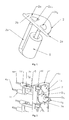
- U shaped solenoid core and (one or two) permanent magnets on the flap This is preferably achieved by a U shaped solenoid core and (one or two) permanent magnets on the flap.
- the U-shaped core 3u (Fig. 1) is located under the display pixel flap pivoting axis 2d as close as possible to the flap and parallel to the display pixel flap pivoting axis 2d, unlike the state-of-the-art solutions using an U shaped magnetic core.
- Such a position and orientation of the U shaped coil core significantly reduces the dependence of flap position on magnetic torque compared to the above mentioned state-of-the-art solutions and reduces the display thickness.
- the permanent magnet arrangement in the flap is either in one piece with antiparallel direction of magnetization, which is also perpendicular to the flap surface and perpendicular to pivoting axis, or divided in two separate segments, which are also magnetized antiparallel.
- the magnets are preferably made of plastic bonded NdFeB material or plastic bonded ferrite material in an injection molding process.
- the design of the magnetic circuit can be optimized by the proper choice of materials using the finite elements method to minimize the energy consumption required for switching from one stable position of the display pixel flap to another.
- the efficiency of the magnetic system, reliability and stability of both bistable positions of the display pixel flap are provided by the increased magnetic torque.
- the proposed design of the magnetic circuit minimizes the stray magnetic field and reduces the magnetic interaction between neighbouring pixels. Therefore there is no need for antiparallel orientation of the magnets in neighbouring display pixel flaps as is the case in US 6,606,458 patent.
- Electromagnetic display pixel driving system is described in detail using Figures 1 - 4 :
- the electromagnet has the preferably U shaped magnetic core oriented along the flap's pivoting axis while the orientation of the magnets in all flaps of the display is the same.
- the display pixel flap has a built in permanent magnet arrangement, which is divided into two areas 2c 1 and 2c 2 .
- the directions of magnetization of these two areas are antiparallel to each other and perpendicular to the pivoting axis of the flap 2d as well as to the flap surface.
- the magnet in the flap 2 can be optionally divided in two separated segments 2c 1 and 2c 2 as shown in Fig. 1.
- the magnetic system consists of the flap 2 with two permanent magnets and an electromagnet (3u+5) .
- the relative magnetization directions of those two magnet segments are the same as in case of one magnet with two areas.
- the magnets are made of plastic bonded NdFeB material or plastic bonded ferrite material.
- the production of the display pixel flap is made in two component injection molding process, during which the magnets are molded during the first step and the rest of the flap is filled with plastic in the second.
- the magnets are molded in the presence of magnetic field, which creates anisotropic magnetic properties, increases the magnetic flux density and gives consequently higher magnetic torque.
- Such a process results in sufficient magnetic torque for the display pixel flap.
- plastic bonded hard magnetic materials the magnetic properties of which are noticeably inferior to the sintered materials
- the above described process still results in sufficient magnetization of the permanent magnets built-in the display pixel flap.
- the magnetization of plastic bonded ferrite magnets is preferably made by permanent rare earth magnets built-in the molding tool.
- the magnetization is preferably made by specially designed current loop built-in the molding tool, which is powered by a very short pulse of a very high electric current.
- the magnetization of the built-in plastic bonded ferrite magnets is made simultaneously for all (for example 14) flaps in a set (Fig. 4). All the flaps in the display have the same magnetic orientation, unlike the solution with straight magnetic core as described in US 6,603458. This significantly simplifies the production and makes process automation easier.
- the electromagnet consists of a solenoid (coil) 5 and the U shaped coil core 3u. It is placed under the rotation axis of the flap and is parallel to the axis (Fig. 1 and Fig. 2). Such an orientation reduces the influence of the flap position on the magnetic torque compared to the state-of-the-art solutions, where U shaped core is oriented perpendicular to the rotation axis.
- the solenoid (coil) is wound up on a plastic solenoid body 1e (Fig. 2), which is part of the monolithic block 1 forming several display pixels.
- the ends of the solenoid wires are soldered to mounting pins 4a and 4b , which are inserted in receptacles 1c and 1d .
- Magnetic core 3u has a U shape and is made of a cylindrically shaped semi hard magnetic material, which gets its final magnetic properties only after adequate thermal treatment.
- One leg of the core is inserted in the coil 5 , the other leg is inserted in block 1 to fix its position.
- the U shaped core enables building thinner displays compared to the case with the straight coil core.
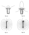
- the magnetic circuit of the display pixel (consisting of the magnetic core of the electromagnet, the magnets in the flap and the air gap between the magnetic core and magnets) is designed and optimized using 3D computer modeling software and is optimized according to the magnetic properties of the materials used.
- the magnetic field in the stable as well as unstable flap positions is shown on Fig. 3.
- This invention is characterized by two simultaneously acting areas of magnetic force in the display pixel flap, which create magnetic torque.
- Such a construction increases the magnetic torque, which is also enhanced by increased magnetic field density when using the electromagnet with the U shaped magnetic core.
- the U shaped magnetic core In comparison to the straight magnetic core, the U shaped magnetic core has significantly less stray magnetic field (Fig. 3). Higher magnetic torque increases the stability of the display pixel flap in "ON” and "OFF" positions.
- An electromagnetic display panel is typically composed of a number of substantially square display pixels organized in display matrix. Due to a reasonably large number of display pixels, the standard production concepts, based on assembling the constituent parts of individual display pixels directly on the display panel main PC board, turns out to be a complex and expensive operation. To reduce costs and simplify the production, 7 pixels are joined in one monolithic block, which is a basic element for building the display matrix.
- the monolithic block 1 (Fig.2) is made of black mate plastic in an injection molding process. After the molding, the block is painted with contrast color in the 1a areas. Then the mounting pins 4a and 4b are inserted in receptacles 1c and 1d . Next operation is winding 7 solenoids on monolithic block 1 and soldering the ends of the winding on mounting pins and testing the ohmic resistance of the windings.
- Magnetic core 3u has a U shape and is made of cylindricaly shaped rod of semi hard magnetic material, which gets its fmal magnetic properties only after adequate thermal treatment.
- One leg of the core is inserted in the coil 5 , the other leg is inserted in block 1 to fix its position.
- the ends of both legs of the core are located under the rotation axis of the flap 2 and are oriented parallely to the said axis.
- the rotatable flaps 2 are manufactured separately. As the flaps 2 have to have built-in permanent magnets 2c 1 , 2c 2 the latter are made using plastic bonded ferrite materials in a two-component injection molding process. Just like with the monolithic block 1 one side 2a of the flaps is painted with the same bright fluorescent paint, while the other half 2b is kept unpainted - mate black original plastic surface.
- the display pixel flap has a built in permanent magnet arrangement, which is divided in two areas (segments) 2c 1 and 2c 2 .
- the direction of magnetization of those areas are antiparallel to each other and prependicular to the pivoting axis of the flap 2d as well as to the flap surface.
- Magnets are made of plastic bonded NdFeB material or plastic bonded ferrite material.
- the production of the display pixel flap is made in a two component injection molding process, during which the magnets are molded during the first step and the rest of the flap is filled with plastic in the second. Magnets are molded in the presence of magnetic field, which creates anisotropic magnetic properties, increases the magnetic flux density and gives consequently higher magnetic torque.
- the magnetization of the plastic bonded ferrite magnets is made by permanent rare earth magnets built-in the molding tool.
- the magnetization is made by specially designed current loop built-in the molding tool, which is powered by a very short pulse of a very high electric current.
- the magnetization of the built-in plastic bonded ferrite magnets is made simultaneously for all 14 flaps in the set (Fig. 4). All the flaps in the display have the same magnetic orientation, unlike the solution with straight magnetic core in US 6,603458. This significantly simplifies the production and makes process automation easier.
- 14 flaps are injection-molded at the same time in two rows of seven flaps (see Fig. 4), connected together with spacers 19 , which keep them positioned at exactly the same place/distance, as determined by the 14 pivoting axes' bearings 1f , 1g on the monolithic block 1 in order to optimize final display segment (7 pixels) assembling process.
- one side 2a of the flaps is painted with the same bright fluorescent paint, while the other half 2b is kept unpainted - mate black original plastic surface.
- the spacers 19 are simultaneously cut away and the two rows of 7 flaps 2 are simultaneously "snapped-in" the 14 pivoting axes' bearings 1f , 1g on the monolithic block 1 .
Landscapes
- Physics & Mathematics (AREA)
- General Physics & Mathematics (AREA)
- Engineering & Computer Science (AREA)
- Theoretical Computer Science (AREA)
- Devices For Indicating Variable Information By Combining Individual Elements (AREA)
- Mechanical Light Control Or Optical Switches (AREA)
- Electrochromic Elements, Electrophoresis, Or Variable Reflection Or Absorption Elements (AREA)
Applications Claiming Priority (2)
| Application Number | Priority Date | Filing Date | Title |
|---|---|---|---|
| SI200400127 | 2004-04-28 | ||
| SI200400127A SI21771A (sl) | 2004-04-28 | 2004-04-28 | Elektromagnetni pogonski sistem prikazovalnika |
Publications (2)
| Publication Number | Publication Date |
|---|---|
| EP1591983A2 true EP1591983A2 (de) | 2005-11-02 |
| EP1591983A3 EP1591983A3 (de) | 2006-08-16 |
Family
ID=34935031
Family Applications (1)
| Application Number | Title | Priority Date | Filing Date |
|---|---|---|---|
| EP05007967A Withdrawn EP1591983A3 (de) | 2004-04-28 | 2005-04-12 | Elektromagnetisches Antriebssystem für Anzeigepixeln |
Country Status (4)
| Country | Link |
|---|---|
| EP (1) | EP1591983A3 (de) |
| CN (1) | CN1691095A (de) |
| RU (1) | RU2288510C2 (de) |
| SI (1) | SI21771A (de) |
Families Citing this family (1)
| Publication number | Priority date | Publication date | Assignee | Title |
|---|---|---|---|---|
| CN105741679A (zh) * | 2016-05-06 | 2016-07-06 | 华通远航(北京)科技发展有限公司 | 一种非led显示器及显示屏 |
Family Cites Families (4)
| Publication number | Priority date | Publication date | Assignee | Title |
|---|---|---|---|---|
| SU824272A1 (ru) * | 1978-03-02 | 1981-04-23 | Предприятие П/Я В-2655 | Элемент индикации |
| US4243978A (en) * | 1979-10-05 | 1981-01-06 | Ferranti-Packard Limited | Display or indicating device with magnetic stop |
| US5898418A (en) * | 1995-03-06 | 1999-04-27 | Kao; Pin-Chi | Magnetically operated display |
| US6603458B1 (en) * | 1998-01-22 | 2003-08-05 | Annex Anzeignsysteme Gmbh | Electromagnetic display device |
-
2004
- 2004-04-28 SI SI200400127A patent/SI21771A/sl not_active IP Right Cessation
- 2004-11-22 RU RU2004134003/09A patent/RU2288510C2/ru not_active IP Right Cessation
- 2004-12-31 CN CN 200410099759 patent/CN1691095A/zh active Pending
-
2005
- 2005-04-12 EP EP05007967A patent/EP1591983A3/de not_active Withdrawn
Also Published As
| Publication number | Publication date |
|---|---|
| RU2288510C2 (ru) | 2006-11-27 |
| RU2004134003A (ru) | 2006-05-10 |
| SI21771A (sl) | 2005-10-31 |
| CN1691095A (zh) | 2005-11-02 |
| EP1591983A3 (de) | 2006-08-16 |
Similar Documents
| Publication | Publication Date | Title |
|---|---|---|
| US8077142B2 (en) | Reflective, bi-stable magneto optical display architectures | |
| US3469258A (en) | Rotating magnetically actuated display or indicator | |
| EP0520418B1 (de) | Vielfarben-Anzeigevorrichtung | |
| CN100581454C (zh) | 磁场发生器和mri装置 | |
| US4769638A (en) | Color graphics information display | |
| EP0877350B1 (de) | Tafel zum Montieren von Anzeigeelementen | |
| AU614268B2 (en) | Display apparatus | |
| EP1591983A2 (de) | Elektromagnetisches Antriebssystem für Anzeigepixeln | |
| US6278431B1 (en) | Magnetically operated display | |
| US5600908A (en) | Displaying element | |
| US6163994A (en) | Display device and array | |
| JPS62258492A (ja) | 表示要素 | |
| KR102283728B1 (ko) | 플립닷 디스플레이 모듈 | |
| EP1591985A2 (de) | Elektromagnetische Anzeigevorrichtung | |
| JP3269705B2 (ja) | 揺動型アクチュエータ | |
| CA2142330C (en) | Displaying element | |
| JP3114007B2 (ja) | 磁気反転表示装置 | |
| JPS5818677A (ja) | 2安定電磁可視標識 | |
| KR880001749B1 (ko) | 다색 표시장치 | |
| JPH02309391A (ja) | 表示器ユニット | |
| JPH0293488A (ja) | 電磁式表示器 | |
| HU217751B (hu) | Jelmegjelenítő elem passzívelemes jelmegjelenítő berendezésekhez | |
| JPS61292303A (ja) | 永久磁石の着磁方法 | |
| HU191973B (en) | Bistabil reproducing element to the display of electromagnetically induced magnetic drop | |
| PL83464B1 (de) |
Legal Events
| Date | Code | Title | Description |
|---|---|---|---|
| PUAI | Public reference made under article 153(3) epc to a published international application that has entered the european phase |
Free format text: ORIGINAL CODE: 0009012 |
|
| AK | Designated contracting states |
Kind code of ref document: A2 Designated state(s): AT BE BG CH CY CZ DE DK EE ES FI FR GB GR HU IE IS IT LI LT LU MC NL PL PT RO SE SI SK TR |
|
| AX | Request for extension of the european patent |
Extension state: AL BA HR LV MK YU |
|
| PUAL | Search report despatched |
Free format text: ORIGINAL CODE: 0009013 |
|
| AK | Designated contracting states |
Kind code of ref document: A3 Designated state(s): AT BE BG CH CY CZ DE DK EE ES FI FR GB GR HU IE IS IT LI LT LU MC NL PL PT RO SE SI SK TR |
|
| AX | Request for extension of the european patent |
Extension state: AL BA HR LV MK YU |
|
| AKX | Designation fees paid | ||
| STAA | Information on the status of an ep patent application or granted ep patent |
Free format text: STATUS: THE APPLICATION IS DEEMED TO BE WITHDRAWN |
|
| 18D | Application deemed to be withdrawn |
Effective date: 20070217 |
|
| REG | Reference to a national code |
Ref country code: DE Ref legal event code: 8566 |