EP1591743A1 - Ventil für Rückstossbremse - Google Patents
Ventil für Rückstossbremse Download PDFInfo
- Publication number
- EP1591743A1 EP1591743A1 EP05290876A EP05290876A EP1591743A1 EP 1591743 A1 EP1591743 A1 EP 1591743A1 EP 05290876 A EP05290876 A EP 05290876A EP 05290876 A EP05290876 A EP 05290876A EP 1591743 A1 EP1591743 A1 EP 1591743A1
- Authority
- EP
- European Patent Office
- Prior art keywords
- valve
- pin
- brake
- bore
- head
- Prior art date
- Legal status (The legal status is an assumption and is not a legal conclusion. Google has not performed a legal analysis and makes no representation as to the accuracy of the status listed.)
- Granted
Links
Images


Classifications
-
- F—MECHANICAL ENGINEERING; LIGHTING; HEATING; WEAPONS; BLASTING
- F41—WEAPONS
- F41A—FUNCTIONAL FEATURES OR DETAILS COMMON TO BOTH SMALLARMS AND ORDNANCE, e.g. CANNONS; MOUNTINGS FOR SMALLARMS OR ORDNANCE
- F41A25/00—Gun mountings permitting recoil or return to battery, e.g. gun cradles; Barrel buffers or brakes
- F41A25/02—Fluid-operated systems
Definitions
- the technical field of the invention is that of valves for fluid circuits and in particular valves implemented between a firing brake and a filler of a armed.
- a firing brake is an organ that is interposed between the recoil mass of a weapon and its cradle. It includes a piston that during the recoil of the weapon moves in a fluid hydraulic. The fluid rolling movement ensures the recoil braking.
- a firing brake is usually connected to a hydraulic filler which is a reserve of fluid under moderate pressure (a few tenths of Mega Pascals (MPa)).
- the purpose of the filler is to compensate for variations of fluid volume following variations in temperatures (ambient and functional).
- the filler is usually connected to the low pressure side of the brake that is to say at the level of the brake chamber whose volume increases during the recoil.
- a valve between the firing brake and the filler. This valve closes when the pressure in the brake exceeds a certain value. This avoids deteriorate the filler by possible overpressures.
- Known valves comprise a sealing member which is movable against the action of a spring whose stiffness allows to determine the closing pressure of the valve.
- a problem with the usual valves is that of the rebound of the valve when the pressure in the room increases rapidly before becoming maximum. A such rebound may communicate to the filler a overpressure can damage it.
- valve between a brake firing and filler for a weapon, valve comprising a movable pin against the action of a return spring, pawn extended by a head having a sealing surface intended to cooperate with a seat to ensure the closure tight of the valve, the closing movement being caused by increasing the pressure of a fluid to the inside of the brake and the side of the pawn, valve characterized in that the pin is slidable in a bore and comprises means allowing a limited leakage of the fluid between the pawn and bore.
- the means of leakage comprise a radial clearance of between 0.08 mm and 0.5 mm.
- the means of escape may also include at least one annular groove made on the pawn.
- the head may include machining operations allowing the fluid passage from the filler to the brake when the valve is in the open position.
- the head can be extended on the side of its sealing range by a guide rod that will sliding climb in a dwelling.
- the valve may comprise an intermediate chamber interposed between bore and housing, surrounding chamber the head of the valve.
- the bore in which the pawn slides may be realized in a rod of the firing brake.
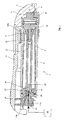
- a firing brake 1 comprises a body 4 which is fixed by one of its ends to a breech sleeve 2.
- the body 4 comprises a head 5 which constitutes a plug closure closing the body 4.
- the head 5 has a stepped profile 6 formed of two cylindrical portions of different diameters, which profile cooperates with complementary shaped machining carried out on the breech sleeve 2.
- the stepped profile 6 of the head 5 cooperates moreover also with a half-flange 8 which also has a internal machining appropriate.
- the half-flange 8 is attached to the bolt sleeve by screws (not shown).
- the brake is here a fur brake comprising a inner shirt 9.
- a rod 10 is slidably mounted in the body 4. It carries at its inner end a piston head 11 which slide in the chamber bounded by the body 4.
- a buffer shock 12 is integral with the body 4 and it cooperates with a internal bore 13 of the rod 10 so as to damp the end of the braking motion.
- the end of the body 4 which is traversed by the rod 10 is closed by a plug 14 which carries means 15 sealing between plug 14 and rod 10.
- the rod 10 carries a head 16 which has a stepped profile formed of three distinct cylindrical diameters. This profile cooperates with two jaws 17a, 17b which are fixed by screws (not shown) in the cradle 3.
- the firing brake 1 is connected to a filler 18 at through a bore 19 disposed inside the rod 10. This bore carries a valve 27 pushed by a spring 28 and which prevents overpressure from reaching the filler 18.
- FIG. 1 shows this valve 27 in its position open which is the one it occupies when the brake is at rest.
- the valve comprises a cylindrical pin 27a which is extended by a head 27b.
- the latter has a range conical seal 29 which is intended to cooperate with a conical seat 30 machined on the head 16 of the rod 10.
- the pawn 27a is slidably mounted in the bore 19 and comprises by elsewhere means allowing a limited leakage of the fluid between its outer cylindrical surface and the bore 19.
- leakage means comprise on the one hand a game of the order of a few tenths of a millimeter between the pin 27a and the bore 19 and on the other hand gorges rings 31 made on the pawn 27a and which make it possible slightly reduce the pressure of the fluid during its passage between pawn and bore.
- the brake 1 comprises a chamber intermediate 35 which is delimited by the conical seat 30 of the valve and by a conical milling 36 that ends the bore 19.
- This intermediate chamber receives the fluid leak passing between the pin 27a and the bore 19. It allows to reduce the fluid pressure coming from the bore 19.
- the valve 27 is extended on the filler side 18 by a cylindrical rod 32 which slides with a game in a housing 33 of the head 16, housing which receives the spring 28.
- the game is also of the order of a few tenths of mm and it is lower than the previous one. It allows the passage of fluid from the filler 18 to the bore 19. This rod 32 guiding the valve relative to the housing 33. It controls the positioning of the sealing surface 29 with respect to its seat 30.
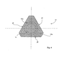
- Figure 4 shows a cross-section of the valve at the level of the head 27b. This section allows to visualize the three machining operations 37 which allow the passage of fluid from the filler 18 to the brake when the valve is in open position.
- the spring 28 is dimensioned so that it ensures maintaining the valve 27 in the open position when the pressure on the side of the bore 19 is less than or equal to about 1 MPa (Mega Pascal).
- the spring is on the other hand depressed and the valve is closed when the side pressure bore 19 is greater than 1 MPa.
- Such a provision maintains the valve in the open position during all the quasi-static movements and a closing of the valve for movements in which a high pressure reigns in the bore 19.
- valve 27 When the weapon is rest position the position of the The valve is that shown in Figure 2.
- the valve 27 is then open and the fluid can circulate as well from filler 18 to the brake 1 that the brake to the filler 18 to come maintain a trimming pressure of the order of a few tenths of MPa.
- the controlled leak of fluid between the pin 27a and the bore 19 allows to postpone the closing of the valve of a few milliseconds.
- Such an arrangement avoids the rebound of the head 27b of the valve against its seat. We thus avoids any transition from high fluid pressure to the filler 18, especially at the end of the movement of back in battery when the pressure is the strongest.
- sealing range 29 and seat 30 have another shape that conical.
Landscapes
- Engineering & Computer Science (AREA)
- General Engineering & Computer Science (AREA)
- Braking Arrangements (AREA)
- Valve Device For Special Equipments (AREA)
- Lift Valve (AREA)
- Valves And Accessory Devices For Braking Systems (AREA)
- Valve-Gear Or Valve Arrangements (AREA)
Applications Claiming Priority (2)
| Application Number | Priority Date | Filing Date | Title |
|---|---|---|---|
| FR0404418 | 2004-04-26 | ||
| FR0404418A FR2869405B1 (fr) | 2004-04-26 | 2004-04-26 | Soupape pour frein de tir |
Publications (2)
| Publication Number | Publication Date |
|---|---|
| EP1591743A1 true EP1591743A1 (de) | 2005-11-02 |
| EP1591743B1 EP1591743B1 (de) | 2008-08-20 |
Family
ID=34942173
Family Applications (1)
| Application Number | Title | Priority Date | Filing Date |
|---|---|---|---|
| EP05290876A Expired - Lifetime EP1591743B1 (de) | 2004-04-26 | 2005-04-20 | Ventil für Rückstossbremse |
Country Status (4)
| Country | Link |
|---|---|
| EP (1) | EP1591743B1 (de) |
| AT (1) | ATE405807T1 (de) |
| DE (1) | DE602005009065D1 (de) |
| FR (1) | FR2869405B1 (de) |
Citations (4)
| Publication number | Priority date | Publication date | Assignee | Title |
|---|---|---|---|---|
| GB129383A (en) * | 1917-11-13 | 1919-07-17 | Armstrong W G Whitworth & Co | Improvements in Hydraulic Buffers for Controlling the Movements of Guns in their Mountings. |
| DE1578048B1 (de) * | 1967-10-27 | 1972-03-09 | Rheinmetall Gmbh | Pneumatischer Rohrvorholer fuer Geschuetze |
| US4867038A (en) * | 1987-08-27 | 1989-09-19 | Rheinmetall Gmbh | Recoil brake for a gun |
| EP1072856A1 (de) * | 1999-07-29 | 2001-01-31 | Giat Industries | Füllstandanzeiger für die Rücklaufbremse einer grosskalibrigen Waffe |
-
2004
- 2004-04-26 FR FR0404418A patent/FR2869405B1/fr not_active Expired - Fee Related
-
2005
- 2005-04-20 EP EP05290876A patent/EP1591743B1/de not_active Expired - Lifetime
- 2005-04-20 AT AT05290876T patent/ATE405807T1/de not_active IP Right Cessation
- 2005-04-20 DE DE602005009065T patent/DE602005009065D1/de not_active Expired - Lifetime
Patent Citations (4)
| Publication number | Priority date | Publication date | Assignee | Title |
|---|---|---|---|---|
| GB129383A (en) * | 1917-11-13 | 1919-07-17 | Armstrong W G Whitworth & Co | Improvements in Hydraulic Buffers for Controlling the Movements of Guns in their Mountings. |
| DE1578048B1 (de) * | 1967-10-27 | 1972-03-09 | Rheinmetall Gmbh | Pneumatischer Rohrvorholer fuer Geschuetze |
| US4867038A (en) * | 1987-08-27 | 1989-09-19 | Rheinmetall Gmbh | Recoil brake for a gun |
| EP1072856A1 (de) * | 1999-07-29 | 2001-01-31 | Giat Industries | Füllstandanzeiger für die Rücklaufbremse einer grosskalibrigen Waffe |
Also Published As
| Publication number | Publication date |
|---|---|
| FR2869405B1 (fr) | 2006-07-28 |
| DE602005009065D1 (de) | 2008-10-02 |
| ATE405807T1 (de) | 2008-09-15 |
| EP1591743B1 (de) | 2008-08-20 |
| FR2869405A1 (fr) | 2005-10-28 |
Similar Documents
| Publication | Publication Date | Title |
|---|---|---|
| BE1007314A3 (fr) | Arme a feu perfectionnee. | |
| EP2048408B1 (de) | Stoßdämpfer eines Fahrzeugs | |
| BE1018580A3 (fr) | Arme a feu d'epaule ameliore. | |
| EP2440806B1 (de) | Stossdämpfer und mit solch einem stossdämpfer versehenes fahrwerk | |
| EP0639726B1 (de) | Einzelstück-Abdichtungsvorrichtung durch eine geschmierte Führung für hydraulische Stossdämpfer | |
| EP3074671B1 (de) | Absperrventil mit einer vakuumkammer | |
| FR2951799A1 (fr) | Soupape de reservoir de gaz | |
| EP0280600A1 (de) | Hydraulischer Kettenspanner | |
| CA2542707C (fr) | Agencement d'assemblage entre une bague interieure de palier et un tourillon, bague et tourillon adaptes a un tel agencement, et turbomachine equipee de ceux-ci | |
| FR2611796A1 (fr) | Dispositif de positionnement | |
| FR3089838A1 (fr) | Appareil hydraulique à percussions équipé d’un dispositif d’étanchéité | |
| EP1591743A1 (de) | Ventil für Rückstossbremse | |
| FR3062888B1 (fr) | Tendeur de courroie | |
| EP0866924B1 (de) | Teleskopdämpfer mit einem laminatkanal | |
| EP1591742B1 (de) | Rückstossbremse | |
| FR2724239A1 (fr) | Dispositif de poussoir etanche, notamment pour commander une piece d'horlogerie | |
| EP1004843B1 (de) | Vorrichtung zu einer temperaturabhängigen Steuerung der Vorlaufgeschwindigkeit eines Geschützes | |
| EP0107117A1 (de) | Hydropneumatische Rückstossbremse mit Energierückgewinnung für Artilleriegeschütze und Handfeuerwaffen | |
| JP2008157382A (ja) | チェーンテンショナ | |
| EP0014126A1 (de) | Verbesserungen an Kolben pneumatischer Federn oder dgl. | |
| FR2821655A1 (fr) | Dispositif d'actionnement de soupape a attenuation de choc | |
| FR3162494A1 (fr) | Vanne anti-retour | |
| FR2985541A1 (fr) | Butee de deconnexion, notamment pour l'actionnement de soupape(s) | |
| FR2997744A1 (fr) | Piston d'amortisseur et amortisseur le comportant. | |
| FR2650041A1 (fr) | Amortisseur oleopneumatique de fin de course |
Legal Events
| Date | Code | Title | Description |
|---|---|---|---|
| PUAI | Public reference made under article 153(3) epc to a published international application that has entered the european phase |
Free format text: ORIGINAL CODE: 0009012 |
|
| AK | Designated contracting states |
Kind code of ref document: A1 Designated state(s): AT BE BG CH CY CZ DE DK EE ES FI FR GB GR HU IE IS IT LI LT LU MC NL PL PT RO SE SI SK TR |
|
| AX | Request for extension of the european patent |
Extension state: AL BA HR LV MK YU |
|
| AKX | Designation fees paid |
Designated state(s): AT BE BG CH CY CZ LI |
|
| 17P | Request for examination filed |
Effective date: 20060425 |
|
| RBV | Designated contracting states (corrected) |
Designated state(s): AT BE BG CH CY CZ DE DK EE ES FI FR GB GR HU IE IS IT LI LT LU MC NL PL PT RO SE SI SK TR |
|
| REG | Reference to a national code |
Ref country code: DE Ref legal event code: 8566 |
|
| RAP1 | Party data changed (applicant data changed or rights of an application transferred) |
Owner name: NEXTER SYSTEMS |
|
| 17Q | First examination report despatched |
Effective date: 20070417 |
|
| GRAP | Despatch of communication of intention to grant a patent |
Free format text: ORIGINAL CODE: EPIDOSNIGR1 |
|
| GRAS | Grant fee paid |
Free format text: ORIGINAL CODE: EPIDOSNIGR3 |
|
| GRAA | (expected) grant |
Free format text: ORIGINAL CODE: 0009210 |
|
| AK | Designated contracting states |
Kind code of ref document: B1 Designated state(s): AT BE BG CH CY CZ DE DK EE ES FI FR GB GR HU IE IS IT LI LT LU MC NL PL PT RO SE SI SK TR |
|
| REG | Reference to a national code |
Ref country code: GB Ref legal event code: FG4D Free format text: NOT ENGLISH |
|
| REG | Reference to a national code |
Ref country code: CH Ref legal event code: EP |
|
| REG | Reference to a national code |
Ref country code: IE Ref legal event code: FG4D Free format text: LANGUAGE OF EP DOCUMENT: FRENCH |
|
| REG | Reference to a national code |
Ref country code: CH Ref legal event code: NV Representative=s name: ING. MARCO ZARDI C/O M. ZARDI & CO. S.A. |
|
| REF | Corresponds to: |
Ref document number: 602005009065 Country of ref document: DE Date of ref document: 20081002 Kind code of ref document: P |
|
| REG | Reference to a national code |
Ref country code: SE Ref legal event code: TRGR |
|
| PG25 | Lapsed in a contracting state [announced via postgrant information from national office to epo] |
Ref country code: NL Free format text: LAPSE BECAUSE OF FAILURE TO SUBMIT A TRANSLATION OF THE DESCRIPTION OR TO PAY THE FEE WITHIN THE PRESCRIBED TIME-LIMIT Effective date: 20080820 Ref country code: LT Free format text: LAPSE BECAUSE OF FAILURE TO SUBMIT A TRANSLATION OF THE DESCRIPTION OR TO PAY THE FEE WITHIN THE PRESCRIBED TIME-LIMIT Effective date: 20080820 Ref country code: IS Free format text: LAPSE BECAUSE OF FAILURE TO SUBMIT A TRANSLATION OF THE DESCRIPTION OR TO PAY THE FEE WITHIN THE PRESCRIBED TIME-LIMIT Effective date: 20081220 |
|
| PG25 | Lapsed in a contracting state [announced via postgrant information from national office to epo] |
Ref country code: FI Free format text: LAPSE BECAUSE OF FAILURE TO SUBMIT A TRANSLATION OF THE DESCRIPTION OR TO PAY THE FEE WITHIN THE PRESCRIBED TIME-LIMIT Effective date: 20080820 Ref country code: SI Free format text: LAPSE BECAUSE OF FAILURE TO SUBMIT A TRANSLATION OF THE DESCRIPTION OR TO PAY THE FEE WITHIN THE PRESCRIBED TIME-LIMIT Effective date: 20080820 Ref country code: ES Free format text: LAPSE BECAUSE OF FAILURE TO SUBMIT A TRANSLATION OF THE DESCRIPTION OR TO PAY THE FEE WITHIN THE PRESCRIBED TIME-LIMIT Effective date: 20081201 Ref country code: AT Free format text: LAPSE BECAUSE OF FAILURE TO SUBMIT A TRANSLATION OF THE DESCRIPTION OR TO PAY THE FEE WITHIN THE PRESCRIBED TIME-LIMIT Effective date: 20080820 |
|
| REG | Reference to a national code |
Ref country code: IE Ref legal event code: FD4D |
|
| PG25 | Lapsed in a contracting state [announced via postgrant information from national office to epo] |
Ref country code: IE Free format text: LAPSE BECAUSE OF FAILURE TO SUBMIT A TRANSLATION OF THE DESCRIPTION OR TO PAY THE FEE WITHIN THE PRESCRIBED TIME-LIMIT Effective date: 20080820 Ref country code: BG Free format text: LAPSE BECAUSE OF FAILURE TO SUBMIT A TRANSLATION OF THE DESCRIPTION OR TO PAY THE FEE WITHIN THE PRESCRIBED TIME-LIMIT Effective date: 20081120 Ref country code: DK Free format text: LAPSE BECAUSE OF FAILURE TO SUBMIT A TRANSLATION OF THE DESCRIPTION OR TO PAY THE FEE WITHIN THE PRESCRIBED TIME-LIMIT Effective date: 20080820 |
|
| PG25 | Lapsed in a contracting state [announced via postgrant information from national office to epo] |
Ref country code: RO Free format text: LAPSE BECAUSE OF FAILURE TO SUBMIT A TRANSLATION OF THE DESCRIPTION OR TO PAY THE FEE WITHIN THE PRESCRIBED TIME-LIMIT Effective date: 20080820 Ref country code: PT Free format text: LAPSE BECAUSE OF FAILURE TO SUBMIT A TRANSLATION OF THE DESCRIPTION OR TO PAY THE FEE WITHIN THE PRESCRIBED TIME-LIMIT Effective date: 20090120 Ref country code: SK Free format text: LAPSE BECAUSE OF FAILURE TO SUBMIT A TRANSLATION OF THE DESCRIPTION OR TO PAY THE FEE WITHIN THE PRESCRIBED TIME-LIMIT Effective date: 20080820 Ref country code: CZ Free format text: LAPSE BECAUSE OF FAILURE TO SUBMIT A TRANSLATION OF THE DESCRIPTION OR TO PAY THE FEE WITHIN THE PRESCRIBED TIME-LIMIT Effective date: 20080820 |
|
| PLBE | No opposition filed within time limit |
Free format text: ORIGINAL CODE: 0009261 |
|
| STAA | Information on the status of an ep patent application or granted ep patent |
Free format text: STATUS: NO OPPOSITION FILED WITHIN TIME LIMIT |
|
| 26N | No opposition filed |
Effective date: 20090525 |
|
| PG25 | Lapsed in a contracting state [announced via postgrant information from national office to epo] |
Ref country code: EE Free format text: LAPSE BECAUSE OF FAILURE TO SUBMIT A TRANSLATION OF THE DESCRIPTION OR TO PAY THE FEE WITHIN THE PRESCRIBED TIME-LIMIT Effective date: 20080820 |
|
| PG25 | Lapsed in a contracting state [announced via postgrant information from national office to epo] |
Ref country code: MC Free format text: LAPSE BECAUSE OF NON-PAYMENT OF DUE FEES Effective date: 20090430 |
|
| PG25 | Lapsed in a contracting state [announced via postgrant information from national office to epo] |
Ref country code: PL Free format text: LAPSE BECAUSE OF FAILURE TO SUBMIT A TRANSLATION OF THE DESCRIPTION OR TO PAY THE FEE WITHIN THE PRESCRIBED TIME-LIMIT Effective date: 20080820 |
|
| PG25 | Lapsed in a contracting state [announced via postgrant information from national office to epo] |
Ref country code: GR Free format text: LAPSE BECAUSE OF FAILURE TO SUBMIT A TRANSLATION OF THE DESCRIPTION OR TO PAY THE FEE WITHIN THE PRESCRIBED TIME-LIMIT Effective date: 20081121 |
|
| PG25 | Lapsed in a contracting state [announced via postgrant information from national office to epo] |
Ref country code: LU Free format text: LAPSE BECAUSE OF NON-PAYMENT OF DUE FEES Effective date: 20090420 |
|
| PG25 | Lapsed in a contracting state [announced via postgrant information from national office to epo] |
Ref country code: HU Free format text: LAPSE BECAUSE OF FAILURE TO SUBMIT A TRANSLATION OF THE DESCRIPTION OR TO PAY THE FEE WITHIN THE PRESCRIBED TIME-LIMIT Effective date: 20090221 |
|
| PG25 | Lapsed in a contracting state [announced via postgrant information from national office to epo] |
Ref country code: TR Free format text: LAPSE BECAUSE OF FAILURE TO SUBMIT A TRANSLATION OF THE DESCRIPTION OR TO PAY THE FEE WITHIN THE PRESCRIBED TIME-LIMIT Effective date: 20080820 |
|
| PG25 | Lapsed in a contracting state [announced via postgrant information from national office to epo] |
Ref country code: CY Free format text: LAPSE BECAUSE OF FAILURE TO SUBMIT A TRANSLATION OF THE DESCRIPTION OR TO PAY THE FEE WITHIN THE PRESCRIBED TIME-LIMIT Effective date: 20080820 |
|
| PGFP | Annual fee paid to national office [announced via postgrant information from national office to epo] |
Ref country code: CH Payment date: 20150324 Year of fee payment: 11 |
|
| PGFP | Annual fee paid to national office [announced via postgrant information from national office to epo] |
Ref country code: SE Payment date: 20150324 Year of fee payment: 11 Ref country code: GB Payment date: 20150324 Year of fee payment: 11 |
|
| PGFP | Annual fee paid to national office [announced via postgrant information from national office to epo] |
Ref country code: IT Payment date: 20150325 Year of fee payment: 11 |
|
| REG | Reference to a national code |
Ref country code: FR Ref legal event code: PLFP Year of fee payment: 12 |
|
| REG | Reference to a national code |
Ref country code: SE Ref legal event code: EUG |
|
| REG | Reference to a national code |
Ref country code: CH Ref legal event code: PL |
|
| GBPC | Gb: european patent ceased through non-payment of renewal fee |
Effective date: 20160420 |
|
| PG25 | Lapsed in a contracting state [announced via postgrant information from national office to epo] |
Ref country code: LI Free format text: LAPSE BECAUSE OF NON-PAYMENT OF DUE FEES Effective date: 20160430 Ref country code: GB Free format text: LAPSE BECAUSE OF NON-PAYMENT OF DUE FEES Effective date: 20160420 Ref country code: CH Free format text: LAPSE BECAUSE OF NON-PAYMENT OF DUE FEES Effective date: 20160430 |
|
| PG25 | Lapsed in a contracting state [announced via postgrant information from national office to epo] |
Ref country code: SE Free format text: LAPSE BECAUSE OF NON-PAYMENT OF DUE FEES Effective date: 20160421 Ref country code: IT Free format text: LAPSE BECAUSE OF NON-PAYMENT OF DUE FEES Effective date: 20160420 |
|
| REG | Reference to a national code |
Ref country code: FR Ref legal event code: PLFP Year of fee payment: 13 |
|
| REG | Reference to a national code |
Ref country code: FR Ref legal event code: PLFP Year of fee payment: 14 |
|
| PGFP | Annual fee paid to national office [announced via postgrant information from national office to epo] |
Ref country code: FR Payment date: 20240320 Year of fee payment: 20 Ref country code: BE Payment date: 20240320 Year of fee payment: 20 |
|
| PGFP | Annual fee paid to national office [announced via postgrant information from national office to epo] |
Ref country code: DE Payment date: 20240320 Year of fee payment: 20 |
|
| REG | Reference to a national code |
Ref country code: BE Ref legal event code: HC Owner name: KNDS FRANCE; FR Free format text: DETAILS ASSIGNMENT: CHANGE OF OWNER(S), CHANGE OF OWNER(S) NAME; FORMER OWNER NAME: NEXTER SYSTEMS Effective date: 20241011 |
|
| REG | Reference to a national code |
Ref country code: DE Ref legal event code: R071 Ref document number: 602005009065 Country of ref document: DE |
|
| REG | Reference to a national code |
Ref country code: BE Ref legal event code: MK Effective date: 20250420 |