EP1591637A2 - Combustion engine - Google Patents
Combustion engine Download PDFInfo
- Publication number
- EP1591637A2 EP1591637A2 EP05103158A EP05103158A EP1591637A2 EP 1591637 A2 EP1591637 A2 EP 1591637A2 EP 05103158 A EP05103158 A EP 05103158A EP 05103158 A EP05103158 A EP 05103158A EP 1591637 A2 EP1591637 A2 EP 1591637A2
- Authority
- EP
- European Patent Office
- Prior art keywords
- turbo compressor
- exhaust gas
- suspension
- combustion engine
- mounting
- Prior art date
- Legal status (The legal status is an assumption and is not a legal conclusion. Google has not performed a legal analysis and makes no representation as to the accuracy of the status listed.)
- Withdrawn
Links
Images

Classifications
-
- F—MECHANICAL ENGINEERING; LIGHTING; HEATING; WEAPONS; BLASTING
- F02—COMBUSTION ENGINES; HOT-GAS OR COMBUSTION-PRODUCT ENGINE PLANTS
- F02B—INTERNAL-COMBUSTION PISTON ENGINES; COMBUSTION ENGINES IN GENERAL
- F02B33/00—Engines characterised by provision of pumps for charging or scavenging
- F02B33/44—Passages conducting the charge from the pump to the engine inlet, e.g. reservoirs
-
- F—MECHANICAL ENGINEERING; LIGHTING; HEATING; WEAPONS; BLASTING
- F02—COMBUSTION ENGINES; HOT-GAS OR COMBUSTION-PRODUCT ENGINE PLANTS
- F02B—INTERNAL-COMBUSTION PISTON ENGINES; COMBUSTION ENGINES IN GENERAL
- F02B37/00—Engines characterised by provision of pumps driven at least for part of the time by exhaust
-
- F—MECHANICAL ENGINEERING; LIGHTING; HEATING; WEAPONS; BLASTING
- F02—COMBUSTION ENGINES; HOT-GAS OR COMBUSTION-PRODUCT ENGINE PLANTS
- F02B—INTERNAL-COMBUSTION PISTON ENGINES; COMBUSTION ENGINES IN GENERAL
- F02B39/00—Component parts, details, or accessories relating to, driven charging or scavenging pumps, not provided for in groups F02B33/00 - F02B37/00
-
- F—MECHANICAL ENGINEERING; LIGHTING; HEATING; WEAPONS; BLASTING
- F02—COMBUSTION ENGINES; HOT-GAS OR COMBUSTION-PRODUCT ENGINE PLANTS
- F02B—INTERNAL-COMBUSTION PISTON ENGINES; COMBUSTION ENGINES IN GENERAL
- F02B67/00—Engines characterised by the arrangement of auxiliary apparatus not being otherwise provided for, e.g. the apparatus having different functions; Driving auxiliary apparatus from engines, not otherwise provided for
- F02B67/10—Engines characterised by the arrangement of auxiliary apparatus not being otherwise provided for, e.g. the apparatus having different functions; Driving auxiliary apparatus from engines, not otherwise provided for of charging or scavenging apparatus
-
- F—MECHANICAL ENGINEERING; LIGHTING; HEATING; WEAPONS; BLASTING
- F01—MACHINES OR ENGINES IN GENERAL; ENGINE PLANTS IN GENERAL; STEAM ENGINES
- F01N—GAS-FLOW SILENCERS OR EXHAUST APPARATUS FOR MACHINES OR ENGINES IN GENERAL; GAS-FLOW SILENCERS OR EXHAUST APPARATUS FOR INTERNAL-COMBUSTION ENGINES
- F01N13/00—Exhaust or silencing apparatus characterised by constructional features
- F01N13/08—Other arrangements or adaptations of exhaust conduits
- F01N13/10—Other arrangements or adaptations of exhaust conduits of exhaust manifolds
-
- F—MECHANICAL ENGINEERING; LIGHTING; HEATING; WEAPONS; BLASTING
- F01—MACHINES OR ENGINES IN GENERAL; ENGINE PLANTS IN GENERAL; STEAM ENGINES
- F01N—GAS-FLOW SILENCERS OR EXHAUST APPARATUS FOR MACHINES OR ENGINES IN GENERAL; GAS-FLOW SILENCERS OR EXHAUST APPARATUS FOR INTERNAL-COMBUSTION ENGINES
- F01N13/00—Exhaust or silencing apparatus characterised by constructional features
- F01N13/18—Construction facilitating manufacture, assembly, or disassembly
- F01N13/1805—Fixing exhaust manifolds, exhaust pipes or pipe sections to each other, to engine or to vehicle body
-
- Y—GENERAL TAGGING OF NEW TECHNOLOGICAL DEVELOPMENTS; GENERAL TAGGING OF CROSS-SECTIONAL TECHNOLOGIES SPANNING OVER SEVERAL SECTIONS OF THE IPC; TECHNICAL SUBJECTS COVERED BY FORMER USPC CROSS-REFERENCE ART COLLECTIONS [XRACs] AND DIGESTS
- Y02—TECHNOLOGIES OR APPLICATIONS FOR MITIGATION OR ADAPTATION AGAINST CLIMATE CHANGE
- Y02T—CLIMATE CHANGE MITIGATION TECHNOLOGIES RELATED TO TRANSPORTATION
- Y02T10/00—Road transport of goods or passengers
- Y02T10/10—Internal combustion engine [ICE] based vehicles
- Y02T10/12—Improving ICE efficiencies
Definitions
- the turbo compressor In a supercharged combustion engine, the turbo compressor is normally mounted by tightening the flange of the turbine casing by screws to the exhaust gas collector. In addition to a screw joint holding the turbo compressor on place, the joint shall also seal against exhaust gas leakage. To accomplish this and to prevent cracks from arising in the exhaust gas collector, when the turbo compressor is suspended from it, a rod is normally required between the turbo compressor and the engine body for handling the often multidimensional load.
- EP 1 176 301 shows a turbo compressor which is tightened to the crankcase by screws. Special suspension devices are integrated in the crankcase for supporting a turbo compressor. Nevertheless, an installer has to hold the turbo compressor with one hand while the other is tightening the screw joint.
- An object of the invention is to reduce the risks for exhaust gas leakage in the joint between the exhaust gas collector and the turbo compressor.
- the mounting device comprises a suspension device arranged on the engine body for suspending the turbo compressor such that the weight of the turbo compressor is supported and that the turbo compressor after the suspension is connectable to the exhaust gas collector.
- An other advantage is that the exhaust gas collector is completely relieved from the weight of the turbo compressor, since the engine body supports it. This implies that the joint between the exhaust gas collector and the turbo compressor can be completely focused on sealing, since it does not have to take the weight of the turbo compressor into consideration. Moreover, the thermal stresses are reduced in the turbine casing at warm/cold cycling, since the casing is not required to be tightened in the same way as before. Consequently, the risks for exhaust gas leakage between the exhaust gas collector and the turbine inlet, and/or the formation of crack are reduced.
- the suspension element comprises a longitudinal, horizontal groove, in which the hooking element can be laterally moved.
- the turbo compressor it is possible to move the turbo compressor in the lateral direction, which promote a correct positioning of the turbo compressor.
- the suspension element comprises a stop element for restricting the lateral movement.
- the positioning can be exact.
- the suspension element is integrated in the engine body.
- the suspension device can be produced when casting the engine body, and separately arranged suspension devices will be redundant.
- the suspension device forms a separate part and is intended to be tightened to the engine body by means of a screw joint.
- the suspension device can be arranged on arbitrary places on the engine body.
- the suspension device is made from cast iron.
- a heat resistant material that will manage the high temperatures that may arise in the vicinity of the turbine is achieved. This facilitates mounting of the turbine, e.g. on a cylinder head made from aluminum, which is far more heat sensitive than cast iron.
- the turbine inlets 13, 15 are coupled to a exhaust gas collector 3, 5, respectively.
- the advantage with a twin-scroll turbine is that the engine more quickly respond when pressing the throttle lever and becomes more fuel efficient.
- the turbo compressor 7 is mounted on the engine body by means of a not shown mounting device, which will be more thoroughly described below.
- the suspension elements 25, 27 and the hooking elements 17, 19 essentially form the mounting device 23.
- the turbo compressor 7 When mounting the turbo compressor on the engine body the turbo compressor 7 is simply hung on the engine body in that the hooking elements 17, 19 are hooked on the suspension elements 25, 27.
- the hooking elements 17, 19 can slide in the grooves 29 of the suspension elements and the turbo compressor be positioned in the lateral direction so that the bolt 21 is aligned with the threaded hole 33. This occurs when one of the hooking elements 17, 19 abuts against the boss 30.
- the whole weight of the turbo compressor is now supported by the suspension elements 25, 27. In this position it is possible to connect the inlets of the turbo compressor to the exhaust gas collectors, whereby the exhaust gas collectors will not be loaded by the weight of the turbo compressor.
- Fig. 4 shows a close up view of the combustion engine in fig. 1 with the cylinder head and the turbo compressor being removed so as to illustrate a second embodiment of a mounting device 23' according to the invention.
- this variant of the suspension device 23' forms a separate part for mounting on the engine body.
- the suspension device forms a bracket 23' and is produced from a heat resistant material, such as cast iron.
- the bracket 23' comprises two fastening portions 24, 26 provided with a through hole, respectively.
- the engine body is provided with two threaded bore holes with the same mutual position as the fastening portions 24, 26, whereby a corresponding bolt joint 35, 37 allows the bracket 23' to be firmly mounted on the engine body.
- the fastening portions 24, 26 also work as a spacer element, which means that a cooling gap is formed between the engine body and the bracket 23' after mounting.
- a spacer element 31' with a threaded bore hole is arranged on the same distance from the suspension elements 25', 27' as the distance between the hooking elements 17, 19 and the bolt 21 in the turbine housing 9.
- a spacer element 31' is formed between the turbo compressor 7 and the engine body which facilitates cooling.
- the suspension elements 25', 27' and the hooking elements 17, 19 essentially form the mounting device 23'.
- the turbo compressor 7 When mounting the turbo compressor on the engine body the turbo compressor 7 is simply hung on the engine body in that the hooking elements 17, 19 are hooked on the suspension elements 25', 27'.
- the hooking elements 17, 19 can slide in the grooves 29 of the suspension elements and the turbo compressor be positioned in the lateral direction, so that the bolt 21 is aligned with the threaded hole 33 in the bracket. This occurs when one of the hooking elements 17, 19 abuts against the boss 30.
- the whole weight of the turbo compressor is now supported by the suspension elements 25', 27'.
Landscapes
- Engineering & Computer Science (AREA)
- Chemical & Material Sciences (AREA)
- Combustion & Propulsion (AREA)
- Mechanical Engineering (AREA)
- General Engineering & Computer Science (AREA)
- Supercharger (AREA)
Abstract
Description
- The present invention relates to a combustion engine for a vehicle comprising at least one exhaust gas collector for receiving the gases combusted in the engine, an exhaust gas driven turbo compressor for connection downstream the exhaust gas collector, and a mounting device for mounting the turbo compressor on the engine.
- The invention also relates to a method of mounting a turbo compressor on a combustion engine, which engine comprises at least one exhaust gas collector for receiving the gases combusted in the engine, an exhaust gas driven turbo compressor for connection downstream the exhaust gas collector and a mounting device for mounting the turbo compressor to the combustion engine.
- In a supercharged combustion engine, the turbo compressor is normally mounted by tightening the flange of the turbine casing by screws to the exhaust gas collector. In addition to a screw joint holding the turbo compressor on place, the joint shall also seal against exhaust gas leakage. To accomplish this and to prevent cracks from arising in the exhaust gas collector, when the turbo compressor is suspended from it, a rod is normally required between the turbo compressor and the engine body for handling the often multidimensional load.
- However, mounting the turbo compressor is not quit simple. An installer needs to hold the turbo compressor on place, at the same time as the flange is tightened to the exhaust gas collector. This is made more difficult since the turbo compressor is rather heavy, at the same time as the space surrounding the engine is narrow.
- US 2003/0005694 shows a turbo compressor which is tightened by screws to the exhaust gas collector. Mounting the turbo compressor implies that the installer holds the turbo compressor with one hand and with the other is tightening the screw joint.
-
EP 1 176 301 shows a turbo compressor which is tightened to the crankcase by screws. Special suspension devices are integrated in the crankcase for supporting a turbo compressor. Nevertheless, an installer has to hold the turbo compressor with one hand while the other is tightening the screw joint. - An object of the invention is to reduce the risks for exhaust gas leakage in the joint between the exhaust gas collector and the turbo compressor.
- Yet an object with the present invention is to simplify the work of an installer when mounting the turbo compressor.
- These objects are achieved by means of a combustion engine as initially defined and which is characterised in that the mounting device comprises a suspension device arranged on the engine body for suspending the turbo compressor such that the weight of the turbo compressor is supported and that the turbo compressor after the suspension is connectable to the exhaust gas collector.
- These objects are also achieved with a method as initially defined and which is characterised by the steps of first suspending the turbo compressor on the engine body by means of the mounting device such that the weight of the turbo compressor is supported, and thereafter connecting the turbo compressor to the exhaust gas collector.
- Since the turbo compressor can be suspended from the engine body before it is connected to the exhaust gas collector mounting is simplified. The reason is that the suspension works as a "third hand" holding the turbo compressor, while the installer, which has his both hands free, can focus on the connection to the exhaust gas collector. Since the working environment often is narrow, unfavorable suspending situations as well as strain injuries can more easily be avoided. Furthermore, a compact installation is achieved since the turbo compressor is positioned closer to the engine body, which s advantageous since space often is lacking in the engine compartment of a vehicle. Neither, no extra rods are required so the number of mounting articles can be reduced.
- An other advantage is that the exhaust gas collector is completely relieved from the weight of the turbo compressor, since the engine body supports it. This implies that the joint between the exhaust gas collector and the turbo compressor can be completely focused on sealing, since it does not have to take the weight of the turbo compressor into consideration. Moreover, the thermal stresses are reduced in the turbine casing at warm/cold cycling, since the casing is not required to be tightened in the same way as before. Consequently, the risks for exhaust gas leakage between the exhaust gas collector and the turbine inlet, and/or the formation of crack are reduced.
- Since the exhaust gas collector is not loaded, it is also conceivable to use exhaust gas collectors made from sheet metal, which are not as load friendly as exhaust gas collectors made from cast iron. The reason why sheet metal is advantageous as material is that it makes it possible to use thinner thicknesses of material. This results in a lighter exhaust gas collector, which more quickly is heated by the exhaust gases. Thus, the catalytic converter will more quickly start to work, since it more rapidly will reach its working temperature, which in the future will be advantageous and necessary from an emission point of view.
- Preferably, the suspension device comprises at least one suspension element and the turbo compressor comprises at least one hooking element, which element are adapted to form-closed interact for supporting the turbo compressor. Hereby, a joint which simplifies mounting and dismounting of the turbo compressor is achieved.
- Suitably, the suspension element comprises a longitudinal, horizontal groove, in which the hooking element can be laterally moved. Hereby, it is possible to move the turbo compressor in the lateral direction, which promote a correct positioning of the turbo compressor.
- Preferably, the suspension element comprises a stop element for restricting the lateral movement. Hereby, the positioning can be exact.
- Preferably, the suspension element is integrated in the engine body. Hereby, the suspension device can be produced when casting the engine body, and separately arranged suspension devices will be redundant.
- Suitably, the suspension device forms a separate part and is intended to be tightened to the engine body by means of a screw joint. Hereby, the suspension device can be arranged on arbitrary places on the engine body.
- Preferably, the suspension device is made from cast iron. Hereby, a heat resistant material that will manage the high temperatures that may arise in the vicinity of the turbine is achieved. This facilitates mounting of the turbine, e.g. on a cylinder head made from aluminum, which is far more heat sensitive than cast iron.
- Suitably, the suspension device comprises elements intended to work as spacers between the engine body and the suspension device. Hereby, the heat transfer between the turbine and the engine body is suppressed, since an isolating air gap is formed between them, which is advantageous from a cooling point of view.
- The invention will now be described with reference to accompanying figures, on which:
- Fig. 1 shows a perspective view of a combustion engine with a turbo compressor according to the invention.
- Fig. 2 shows a perspective view of the turbo compressor in fig. 1.
- Fig. 3 shows a perspective view of a first embodiment of a suspension device.
- Fig. 4 shows a perspective view of a second embodiment of a suspension device.
-
- Fig. 1 shows a
combustion engine 1 in the shape of a transverse V6 engine having 3 cylinders per bank, even though other numbers of cylinders are conceivable.
The first cylinder bank leads exhaust gases to a first exhaust gas collector 3, and the second cylinder bank leads exhaust gases to a second exhaust gas collector 5. The first and the second exhaust gas collectors are separated and thus not in fluid communication with each other. The engine is moreover supercharged with the aid of an exhaust gas driven turbo compressor 7 having a turbine 9 and a compressor 11 driven by the turbine (see fig.2). The turbine 9 is of a so called twin-scroll model, which means that it has double spirally shaped inlets 13, 15 to the turbine wheel, but the invention is not restricted to such a model. The turbine inlets 13, 15 are coupled to a exhaust gas collector 3, 5, respectively. The advantage with a twin-scroll turbine is that the engine more quickly respond when pressing the throttle lever and becomes more fuel efficient. The turbo compressor 7 is mounted on the engine body by means of a not shown mounting device, which will be more thoroughly described below. - Fig. 2 shows that the turbine housing 9 of the turbo compressor 7 is provided with two, substantially hook shaped hooking
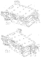
elements 17, 19, on the side of the turbine housing which after assembly is facing the engine body. Theseelements 17, 19 are formed directly in the castings and thus form an integrated part of the turbine housing. The hooking elements are arranged on a distance from each other and on substantially the same height. In the casting of the turbine housing, below the hooking elements, a bolt 21 is arranged for mounting of the turbo compressor on the engine body. - Fig. 3 shows a close up view of the combustion engine in fig. 1 with the cylinder head and the turbo compressor removed, so as to illustrate a first embodiment of a mounting device 23 according to the invention. It comprises a suspension device 23 in the form of two
suspension elements 25, 27. These are formed directly in the engine body and thereby form an integrated part of it. Thesuspension elements 25, 27 are mutually arranged on substantially the same height. The distance between the suspension elements corresponds to the distance between the hookingelements 17, 19 of the turbine housing 9. Eachsuspension element 25, 27 comprises a cut outlongitudinal groove 29 with a shape that substantially correspond to the appearance and dimension of the hookingelements 17, 19, whereby the hookingelements 17, 19 form-closed can interact with thesuspension elements 25, 27. In each end of the groove, asmall stop element 30 in the form of aboss 30 is disposed. Below the suspension elements, a spacer element 31 with a threadedhole 33 is disposed on the same distance from thesuspension elements 25, 27 as the distance between the hookingelements 17, 19 and the bolt 21. By means of the spacer element 31 a space is formed between the turbo compressor 7 and the engine body which facilitates cooling. - The
suspension elements 25, 27 and the hookingelements 17, 19 essentially form the mounting device 23. When mounting the turbo compressor on the engine body the turbo compressor 7 is simply hung on the engine body in that the hookingelements 17, 19 are hooked on thesuspension elements 25, 27. On place, the hookingelements 17, 19 can slide in thegrooves 29 of the suspension elements and the turbo compressor be positioned in the lateral direction so that the bolt 21 is aligned with the threadedhole 33. This occurs when one of the hookingelements 17, 19 abuts against theboss 30. The whole weight of the turbo compressor is now supported by thesuspension elements 25, 27. In this position it is possible to connect the inlets of the turbo compressor to the exhaust gas collectors, whereby the exhaust gas collectors will not be loaded by the weight of the turbo compressor. - Fig. 4 shows a close up view of the combustion engine in fig. 1 with the cylinder head and the turbo compressor being removed so as to illustrate a second embodiment of a mounting device 23' according to the invention. In contrast to the first embodiment, this variant of the suspension device 23' forms a separate part for mounting on the engine body. The suspension device forms a bracket 23' and is produced from a heat resistant material, such as cast iron. The bracket 23' comprises two
fastening portions 24, 26 provided with a through hole, respectively. The engine body is provided with two threaded bore holes with the same mutual position as thefastening portions 24, 26, whereby a corresponding bolt joint 35, 37 allows the bracket 23' to be firmly mounted on the engine body. Thefastening portions 24, 26 also work as a spacer element, which means that a cooling gap is formed between the engine body and the bracket 23' after mounting. - Moreover, the mounting device according to this second embodiment is similar concerning function and appearance as the earlier described embodiment. Thus, the suspension device 23' comprises two suspension elements 25', 27', which are mutually arranged on substantially the same height. The distance between the suspension elements corresponds to the distance between the hooking
elements 17, 19 of the turbine housing. Each suspension element 25', 27' comprises a cut out longitudinal groove 29' with a shape that substantially correspond to the shape and the appearance of the hooking elements, whereby the hookingelements 17, 19 form-closed can interact with the suspension elements 25', 27'. In each end of the groove a small stop element 30' in the shape of a boss 30' is arranged. Below the suspension elements a spacer element 31' with a threaded bore hole is arranged on the same distance from the suspension elements 25', 27' as the distance between the hookingelements 17, 19 and the bolt 21 in the turbine housing 9. By means of the spacer element 31' a space is formed between the turbo compressor 7 and the engine body which facilitates cooling. - The suspension elements 25', 27' and the hooking
elements 17, 19 essentially form the mounting device 23'. When mounting the turbo compressor on the engine body the turbo compressor 7 is simply hung on the engine body in that the hookingelements 17, 19 are hooked on the suspension elements 25', 27'. On place the hookingelements 17, 19 can slide in thegrooves 29 of the suspension elements and the turbo compressor be positioned in the lateral direction, so that the bolt 21 is aligned with the threadedhole 33 in the bracket. This occurs when one of the hookingelements 17, 19 abuts against theboss 30. The whole weight of the turbo compressor is now supported by the suspension elements 25', 27'. In this position it is possible to connect the inlets of the turbo compressor to the exhaust gas collectors, whereby the exhaust gas collectors will not be loaded by the weight of the turbo compressor. The advantage with this embodiment compared to the first embodiment described is that it provides for a worse heat transfer between the engine body and the turbo compressor, which may be of importance in case, e.g. the cylinder head is made from aluminum, and thereby has difficulties to resist the high temperatures that arise in the turbine. The bracket will then act as a spacer element distancing the turbine from the cylinder head so that a better cooling can be performed. - Of course it is also possible that the compressor housing is provided with the hooking elements and not only the turbine housing. It is also conceivable that the mounting of the turbo compressor takes place in the cylinder head.
Claims (9)
- Combustion engine (1) for a vehicle comprising:characterised in that the mounting device comprises:at least one exhaust gas collector (3, 5) for receiving the gases combusted in the engine (1),an exhaust gas driven turbo compressor (7) for connection downstream the exhaust gas collector, anda mounting device (23, 23') for mounting the turbo compressor (7) on the engine (1),a suspension device (23, 23') arranged on the engine body for suspending the turbo compressor (7) such that the weight of the turbo compressor (7) is supported and that the turbo compressor (7) after the suspension is connectable to the exhaust gas collector (3, 5).
- Combustion engine according to claim 1, wherein the suspension device (23; 23') comprises at least a suspension element (25, 27; 25', 27') and the turbo compressor (7) comprises at least one hooking element (17, 19), which elements are adapted to form-closed interact for suspending the turbo compressor (7).
- Combustion engine according to claim 2, wherein the suspension element (25, 27; 25', 27') comprises a longitudinal, horizontal groove (29; 29') in which the hooking element (17, 19) can be laterally moved.
- Combustion engine according to claim 3, wherein the suspension element (25, 27; 25', 27') comprises a stop element (30; 30') for restricting said lateral movement.
- Combustion engine according to any of the previous claims, wherein the suspension device (23) is integrated in the engine body.
- Combustion engine according to any of claim 1-4, wherein the suspension device (23') forms a separate part and is intended to be tightened to the engine body by means of a screw joint (35, 37).
- Combustion engine according to claim 6, wherein the suspension device (23; 23') is made from cast iron.
- Combustion engine according to claim 7, wherein the suspension device (23; 23') comprises elements (31; 31') adapted to act as spacers between the engine body and the suspension device.
- Method of mounting a turbo compressor on a combustion engine (1), which engine comprises at least one exhaust gas collector (3, 5) for receiving the gases combusted in the engine, an exhaust gas driven turbo compressor (7) for connection downstream the exhaust gas collector (3, 5), and a mounting device (23, 23') for mounting the turbo compressor to the combustion engine, characterised by the steps of first suspending the turbo compressor (7) on the engine body by means of the mounting device (23; 23') such that the weight of the turbo compressor is supported, and thereafter connecting the turbo compressor to the exhaust gas collector (3, 5).
Applications Claiming Priority (2)
| Application Number | Priority Date | Filing Date | Title |
|---|---|---|---|
| SE0401106 | 2004-04-29 | ||
| SE0401106A SE527909C2 (en) | 2004-04-29 | 2004-04-29 | Internal combustion engine |
Publications (2)
| Publication Number | Publication Date |
|---|---|
| EP1591637A2 true EP1591637A2 (en) | 2005-11-02 |
| EP1591637A3 EP1591637A3 (en) | 2007-01-24 |
Family
ID=32322704
Family Applications (1)
| Application Number | Title | Priority Date | Filing Date |
|---|---|---|---|
| EP05103158A Withdrawn EP1591637A3 (en) | 2004-04-29 | 2005-04-20 | Combustion engine |
Country Status (3)
| Country | Link |
|---|---|
| US (1) | US7165402B2 (en) |
| EP (1) | EP1591637A3 (en) |
| SE (1) | SE527909C2 (en) |
Families Citing this family (3)
| Publication number | Priority date | Publication date | Assignee | Title |
|---|---|---|---|---|
| US8234867B2 (en) * | 2008-06-25 | 2012-08-07 | Ford Global Technologies, Llc | Turbocharger system for internal combustion engine with internal isolated turbocharger oil drainback passage |
| US8245511B2 (en) * | 2008-06-25 | 2012-08-21 | Ford Global Technologies, Llc | Cylinder block mounted pedestal and turbocharger system for internal combustion engine |
| US8215113B2 (en) * | 2008-06-25 | 2012-07-10 | Ford Global Technologies, Llc | Pedestal mounted turbocharger system for internal combustion engine |
Citations (2)
| Publication number | Priority date | Publication date | Assignee | Title |
|---|---|---|---|---|
| EP1176301A2 (en) | 2000-07-25 | 2002-01-30 | Volkswagen Aktiengesellschaft | Crank case for an internal combustion engine |
| US20030005694A1 (en) | 2001-06-21 | 2003-01-09 | Christoph Pleuss | Apparatus for fastening an exhaust gas turbocharger on an exhaust chamber of a combustion engine |
Family Cites Families (26)
| Publication number | Priority date | Publication date | Assignee | Title |
|---|---|---|---|---|
| US2175106A (en) * | 1938-05-05 | 1939-10-03 | Thomas H Burns | Supercharger |
| US2810514A (en) * | 1955-07-08 | 1957-10-22 | Hupp Corp | Supporting and positioning means for blowers or the like |
| DD136281A1 (en) * | 1977-12-23 | 1979-06-27 | Helmut Weisshaupt | INTERNAL COMBUSTION ENGINE WITH TWO-STAGE EXHAUST GAS BOARDS |
| DD156619A1 (en) * | 1981-02-26 | 1982-09-08 | Hans Standhardt | ARRANGEMENT FOR FIXING AN EXHAUST BURNER TO INTERNAL COMBUSTION ENGINES |
| US4483147A (en) * | 1981-04-27 | 1984-11-20 | Evans Hugh G | Turbocharged engine having an engine speed and throttle position responsive compressor bleed valve |
| DE3341119C1 (en) * | 1983-11-12 | 1985-06-20 | Dr.Ing.H.C. F. Porsche Ag, 7000 Stuttgart | Support arm for an internal combustion engine |
| DD220792B1 (en) * | 1984-01-26 | 1988-02-03 | Schwermasch Liebknecht Veb K | APPARATUS FOR AGGREGATE ARRANGEMENT AT THE HOUSING BLOCK OF INTERNAL COMBUSTION ENGINES |
| JPH034756Y2 (en) * | 1985-08-27 | 1991-02-07 | ||
| DE3532695C1 (en) * | 1985-09-13 | 1986-11-27 | Audi AG, 8070 Ingolstadt | Exhaust gas turbocharger for a vehicle internal combustion engine |
| JPS62182433A (en) * | 1986-02-04 | 1987-08-10 | Daihatsu Motor Co Ltd | Engine for vehicle having turbo charger |
| DE3641550C1 (en) * | 1986-12-05 | 1988-03-03 | Audi Ag | Arrangement of exhaust turbocharger, blow-off valve and exhaust manifold on a multi-cylinder internal combustion engine |
| US5392751A (en) * | 1992-09-24 | 1995-02-28 | Mazda Motor Corporation | V-type engine with supercharger mounting |
| US5261237A (en) * | 1992-11-30 | 1993-11-16 | Benson Steven R | Oil drain and turbo assembly support |
| US5938169A (en) * | 1996-11-26 | 1999-08-17 | Suzuki Motor Corporation | Engine mounting for engine accessory |
| JPH10238819A (en) * | 1997-02-21 | 1998-09-08 | Matsushita Electric Ind Co Ltd | Outdoor unit fixture for separation type air conditioner |
| JP3740935B2 (en) * | 1999-03-18 | 2006-02-01 | いすゞ自動車株式会社 | Supercharged V-type engine |
| US6378309B1 (en) * | 2000-12-19 | 2002-04-30 | Caterpillar Inc. | Single air inlet |
| JP3966019B2 (en) * | 2002-02-27 | 2007-08-29 | 株式会社デンソー | Mounting structure for heavy objects to be mounted |
| EP1428999A1 (en) * | 2002-12-12 | 2004-06-16 | Renault s.a.s. | Supercharger arrangements for engine assemblies |
| JP4185764B2 (en) * | 2002-12-16 | 2008-11-26 | 日野自動車株式会社 | Engine accessory drive device |
| FR2849104B1 (en) * | 2002-12-19 | 2005-02-11 | Renault Sa | AUTOMOTIVE VEHICLE EXHAUST MANIFOLD COMPRISING A SUPPORT BRACKET OF A COMPONENT |
| FR2852624B1 (en) * | 2003-03-17 | 2006-04-28 | Renault Sa | DEVICE FOR FASTENING A TURBOCHARGER ON A COMBUSTION ENGINE |
| DE10323731A1 (en) * | 2003-05-24 | 2004-12-09 | Daimlerchrysler Ag | Exhaust turbocharger for an internal combustion engine with temperature-loaded turbine casing, has shield element to reduce heat transfer between turbine casing and surrounding area |
| FR2856735B1 (en) * | 2003-06-30 | 2005-09-02 | Renault Sa | ENGINE COMPRISING A CATALYST AND A TURBOCHARGER FIXED ON THE CYLINDER BLOCK BY MEANS OF A COMMON SUPPORT |
| FR2856736B1 (en) * | 2003-06-30 | 2005-09-02 | Renault Sa | ENGINE COMPRISING A TURBOCHARGER MOUNTED ON A FREESTROUGH HOLDING SHAFT |
| US20050028795A1 (en) * | 2003-08-07 | 2005-02-10 | Benson Robert C. | Boosting mechanism for internal combustion engines |
-
2004
- 2004-04-29 SE SE0401106A patent/SE527909C2/en not_active IP Right Cessation
-
2005
- 2005-04-20 EP EP05103158A patent/EP1591637A3/en not_active Withdrawn
- 2005-04-29 US US11/118,669 patent/US7165402B2/en not_active Expired - Fee Related
Patent Citations (2)
| Publication number | Priority date | Publication date | Assignee | Title |
|---|---|---|---|---|
| EP1176301A2 (en) | 2000-07-25 | 2002-01-30 | Volkswagen Aktiengesellschaft | Crank case for an internal combustion engine |
| US20030005694A1 (en) | 2001-06-21 | 2003-01-09 | Christoph Pleuss | Apparatus for fastening an exhaust gas turbocharger on an exhaust chamber of a combustion engine |
Also Published As
| Publication number | Publication date |
|---|---|
| SE0401106L (en) | 2005-10-30 |
| US20050241307A1 (en) | 2005-11-03 |
| EP1591637A3 (en) | 2007-01-24 |
| US7165402B2 (en) | 2007-01-23 |
| SE0401106D0 (en) | 2004-04-29 |
| SE527909C2 (en) | 2006-07-11 |
Similar Documents
| Publication | Publication Date | Title |
|---|---|---|
| CN102472145B (en) | Muffler attachment system | |
| US8733088B2 (en) | Exhaust manifold system and collar coolant jacket | |
| US20120104224A1 (en) | Method and device for fastening an exhaust gas converter module | |
| JP2010038091A (en) | Internal combustion engine with supercharger | |
| US7165402B2 (en) | Combustion engine | |
| CA2666849A1 (en) | Method and device for disposing of air compression system effluent | |
| CN203925713U (en) | Refrigerating module | |
| EP2961956B1 (en) | Exhaust manifold with turbo support | |
| US20160178105A1 (en) | Exhaust Outlet Elbow Bolt Pattern | |
| CN102770632B (en) | Manifold component | |
| EP2075429A1 (en) | An engine and exhaust manifold assembly | |
| US20030056505A1 (en) | Exhaust gas manifold of an exhaust system for an internal combustion engine | |
| US5359159A (en) | Internal combustion engine | |
| US7258094B1 (en) | Engine block component brace | |
| US9719402B2 (en) | Exhaust runner collar | |
| JP5556743B2 (en) | Air intake structure of a turbocharged engine | |
| JPH07310540A (en) | Exhaust device for internal combustion engine | |
| EP3289210A1 (en) | Cylinder block with egr cooler housing | |
| JP4438523B2 (en) | Turbocharger and turbocharged engine | |
| JPH055224Y2 (en) | ||
| EP1288555A3 (en) | Flange for pipe connections | |
| JP2970345B2 (en) | Engine exhaust system | |
| JP3494881B2 (en) | Exhaust manifold for internal combustion engine | |
| JP2018173007A (en) | Engine and vehicle | |
| KR100633924B1 (en) | Engine hanger |
Legal Events
| Date | Code | Title | Description |
|---|---|---|---|
| PUAI | Public reference made under article 153(3) epc to a published international application that has entered the european phase |
Free format text: ORIGINAL CODE: 0009012 |
|
| AK | Designated contracting states |
Kind code of ref document: A2 Designated state(s): AT BE BG CH CY CZ DE DK EE ES FI FR GB GR HU IE IS IT LI LT LU MC NL PL PT RO SE SI SK TR |
|
| AX | Request for extension of the european patent |
Extension state: AL BA HR LV MK YU |
|
| PUAL | Search report despatched |
Free format text: ORIGINAL CODE: 0009013 |
|
| AK | Designated contracting states |
Kind code of ref document: A3 Designated state(s): AT BE BG CH CY CZ DE DK EE ES FI FR GB GR HU IE IS IT LI LT LU MC NL PL PT RO SE SI SK TR |
|
| AX | Request for extension of the european patent |
Extension state: AL BA HR LV MK YU |
|
| 17P | Request for examination filed |
Effective date: 20070628 |
|
| AKX | Designation fees paid |
Designated state(s): AT BE BG CH CY CZ DE DK EE ES FI FR GB GR HU IE IS IT LI LT LU MC NL PL PT RO SE SI SK TR |
|
| STAA | Information on the status of an ep patent application or granted ep patent |
Free format text: STATUS: THE APPLICATION IS DEEMED TO BE WITHDRAWN |
|
| 18D | Application deemed to be withdrawn |
Effective date: 20071101 |