EP1591261A2 - Image forming apparatus and detachable part - Google Patents
Image forming apparatus and detachable part Download PDFInfo
- Publication number
- EP1591261A2 EP1591261A2 EP05001565A EP05001565A EP1591261A2 EP 1591261 A2 EP1591261 A2 EP 1591261A2 EP 05001565 A EP05001565 A EP 05001565A EP 05001565 A EP05001565 A EP 05001565A EP 1591261 A2 EP1591261 A2 EP 1591261A2
- Authority
- EP
- European Patent Office
- Prior art keywords
- image forming
- mode
- forming apparatus
- replaceable
- operation mode
- Prior art date
- Legal status (The legal status is an assumption and is not a legal conclusion. Google has not performed a legal analysis and makes no representation as to the accuracy of the status listed.)
- Granted
Links
Images




Classifications
-
- G—PHYSICS
- G03—PHOTOGRAPHY; CINEMATOGRAPHY; ANALOGOUS TECHNIQUES USING WAVES OTHER THAN OPTICAL WAVES; ELECTROGRAPHY; HOLOGRAPHY
- G03G—ELECTROGRAPHY; ELECTROPHOTOGRAPHY; MAGNETOGRAPHY
- G03G15/00—Apparatus for electrographic processes using a charge pattern
- G03G15/06—Apparatus for electrographic processes using a charge pattern for developing
- G03G15/08—Apparatus for electrographic processes using a charge pattern for developing using a solid developer, e.g. powder developer
- G03G15/0822—Arrangements for preparing, mixing, supplying or dispensing developer
- G03G15/0863—Arrangements for preparing, mixing, supplying or dispensing developer provided with identifying means or means for storing process- or use parameters, e.g. an electronic memory
-
- G—PHYSICS
- G03—PHOTOGRAPHY; CINEMATOGRAPHY; ANALOGOUS TECHNIQUES USING WAVES OTHER THAN OPTICAL WAVES; ELECTROGRAPHY; HOLOGRAPHY
- G03G—ELECTROGRAPHY; ELECTROPHOTOGRAPHY; MAGNETOGRAPHY
- G03G15/00—Apparatus for electrographic processes using a charge pattern
- G03G15/06—Apparatus for electrographic processes using a charge pattern for developing
- G03G15/08—Apparatus for electrographic processes using a charge pattern for developing using a solid developer, e.g. powder developer
- G03G15/0894—Reconditioning of the developer unit, i.e. reusing or recycling parts of the unit, e.g. resealing of the unit before refilling with toner
-
- G—PHYSICS
- G03—PHOTOGRAPHY; CINEMATOGRAPHY; ANALOGOUS TECHNIQUES USING WAVES OTHER THAN OPTICAL WAVES; ELECTROGRAPHY; HOLOGRAPHY
- G03G—ELECTROGRAPHY; ELECTROPHOTOGRAPHY; MAGNETOGRAPHY
- G03G15/00—Apparatus for electrographic processes using a charge pattern
- G03G15/55—Self-diagnostics; Malfunction or lifetime display
-
- G—PHYSICS
- G03—PHOTOGRAPHY; CINEMATOGRAPHY; ANALOGOUS TECHNIQUES USING WAVES OTHER THAN OPTICAL WAVES; ELECTROGRAPHY; HOLOGRAPHY
- G03G—ELECTROGRAPHY; ELECTROPHOTOGRAPHY; MAGNETOGRAPHY
- G03G21/00—Arrangements not provided for by groups G03G13/00 - G03G19/00, e.g. cleaning, elimination of residual charge
- G03G21/16—Mechanical means for facilitating the maintenance of the apparatus, e.g. modular arrangements
- G03G21/18—Mechanical means for facilitating the maintenance of the apparatus, e.g. modular arrangements using a processing cartridge, whereby the process cartridge comprises at least two image processing means in a single unit
- G03G21/1875—Mechanical means for facilitating the maintenance of the apparatus, e.g. modular arrangements using a processing cartridge, whereby the process cartridge comprises at least two image processing means in a single unit provided with identifying means or means for storing process- or use parameters, e.g. lifetime of the cartridge
- G03G21/1878—Electronically readable memory
- G03G21/1892—Electronically readable memory for presence detection, authentication
-
- G—PHYSICS
- G03—PHOTOGRAPHY; CINEMATOGRAPHY; ANALOGOUS TECHNIQUES USING WAVES OTHER THAN OPTICAL WAVES; ELECTROGRAPHY; HOLOGRAPHY
- G03G—ELECTROGRAPHY; ELECTROPHOTOGRAPHY; MAGNETOGRAPHY
- G03G2215/00—Apparatus for electrophotographic processes
- G03G2215/06—Developing structures, details
- G03G2215/066—Toner cartridge or other attachable and detachable container for supplying developer material to replace the used material
- G03G2215/0695—Toner cartridge or other attachable and detachable container for supplying developer material to replace the used material using identification means or means for storing process or use parameters
Definitions
- a method for switching an operation mode of an image forming apparatus such as a copier or printer
- a service engineer having special knowledge switches the operation mode using specialized service tools, such as, for example, a control panel service mode, a specialized hand tool, proprietary software running on a PC, or the like.
- This method is employed when free switching by a user is not preferable from the viewpoint of safety.
- the user must very inconveniently contact the service engineer each time the user wishes the operation mode to be switched. Further, the manufacturer or a seller must dispatch the service engineer to the installed place of the image forming apparatus every time the operation mode is switched, which can greatly increase costs and reduce the profitability of service packages.
- Still another aspect of the present invention provides an image forming apparatus for forming an image on a recording medium, which includes an image forming apparatus main body having multiple operation modes and a replaceable part detachably attached to the image forming apparatus main body. Operation mode switching information for switching the operation modes of the image forming apparatus main body is held in the replaceable part. The image forming apparatus main body switches the operation mode or modes in accordance with the operation mode switching information stored in the replaceable part when the replaceable part is attached.
- Still another aspect of the present invention provides an image forming apparatus main body that has multiple operation modes and forms an image on a recording medium by using detachably attached replaceable part.
- the image forming apparatus main body has an attaching section to which a replaceable part holding operation mode switching information for switching the operation modes can be attached and an operation mode switching section that switches the operation mode on the basis of the operation mode switching information stored in the replaceable part when the replaceable part is attached to the attaching section.
- Fig. 1 is a block diagram showing a schematic structure of an image forming apparatus 1 according to a first embodiment of the present invention.
- the image forming apparatus 1 is an apparatus such as a copier, printer, fax machine, or the like for printing an image on a recording material, such as a sheet of paper.
- a copier, printer, fax machine, or the like for printing an image on a recording material, such as a sheet of paper.
- an electro-photographic system is explained as an example of a printing system.
- other systems such as an ink jet system, may be employed.
- a manufacturer of an image forming section 10 assumes that a genuine replaceable part 30 is attached to the image forming section 10 when designing and manufacturing the image forming section 10 so as to obtain a prescribed quality (image quality, durability, safety performance, etc.). Accordingly, when the genuine replaceable part 30 of the manufacturer is attached to the image forming section 10, the prescribed quality can be obtained. Further, replaceableparts may not be limited to the genuine part. When a replaceable part 30 is produced by another manufacturer and its use is permitted by the manufacturer, such as a recommended replacement part or licensed component, a certain degree of quality can be anticipated because operation when the replaceable parts 30 is attached is within the range of the manufacturer's assumptions. In the specification of this application, replaceable parts whose use is approved by the manufacturer, including original parts, recommended parts, or the like, are all commonly referred to hereinafter as "approved parts".
- an unapproved part mode for attaching an unapproved part is provided as well as an approved part mode corresponding to cases wherein the approved part is attached to the image forming section.
- the unapproved part mode is an operation mode that satisfies the desire of the consumer who wishes to use the unapproved part and avoids disadvantages caused by the use of the unapproved part.
- the switching section 20 switches the operation mode of the image forming section 10 between the approved part mode and the unapproved part mode.
- the operation mode may be switched either manually or automatically by the switching section 20.
- Fig. 2 is a block diagram showing a detailed structure of the image forming apparatus 1 according to this embodiment. Now, by referring to Fig. 2, the structure and operation of the image forming apparatus 1 will be more specifically described.
- the photosensitive drum 1a, the charging device 1b, and the cleaner 1g form an integrally formed drum cartridge 30A.
- the drum cartridge 30A is detachably attached to the image forming section 10 as the replaceable part 30.
- a toner cartridge 30B with which the toner supplied to the developing device 1d is filled is detachably attached to the image forming section 10 as the replaceable part 30.
- the image forming section 10 includes a charging power source 10B for applying charging bias to the charging device 1b, a power source 10C for exposure for driving a laser light source of the ROS 1c, a developing power source 10D for applying developing bias to the developing device 1d, a transferring power source 10E for applying transferring bias to the transfer roll 1e, and a fixing power source 10F for supplying electric power to the heater of the fixing device 1f.
- the image forming section 10 is provided with a controller 11 for controlling the entire image forming section 10 including the power sources 10B to 10F.
- the image forming section 10 is provided with a control panel that is not shown.
- the control panel is a touch panel type user interface for displays various information and for receiving the input of an instruction of a user.
- "user” includes a manager of an apparatus for managing the image forming apparatus 1 or a service engineer for performing maintenance, as well as an ordinary user.
- nonvolatile memories 31A and 31B for storing control information used for an image forming operation are respectively attached.
- the information in the nonvolatile memories 31A and 31B is read and written by reader/writer 13A and 13B provided in the image forming section 10.
- the non-volatile memory 31 is an RFID (Radio Frequency Identification) tag to transmit the information to and receive the information from the reader/writer 13 by wireless.
- the nonvolatile memory 31 is not limited to a specific nonvolatile memory and may transmit the information to and receive the information from the reader/writer 13 through a wired connection.
- the switching section 20 obtains information showing whether or not the cartridge is the approved part from the attached drum cartridge 30A to discriminate whether or not the drum cartridge 30A is the approved part on the basis of the obtained information (S112). For example, the switching section 20 reads encoded information stored in the nonvolatile memory 31A by the reader/writer 13A to decide whether or not the drum cartridge 30A is the approved part depending on whether or not the encoded information can be properly decoded. In such a case, the information showing whether or not the drum cartridge 30A is the approved part may be other information such as a bar code (not shown) attached to the drum cartridge 30A or a physical characteristic value of the drum cartridge 30A. A method for determining whether or not the drum cartridge is the approved part is not limited to a specific method.
- the prescribed switching operation may be an operation in which a password is input from the user interface such as the control panel.
- the switching section 20 collates the input password with a previously held password and receives the instruction for switching the operation mode when the input password corresponds to the previously held password.
- the switching operation may be limited to that person.
- the specific manner of the switching operation is not limited.
- the image forming apparatus 1 waits until the image forming apparatus receives an instruction for forming an image, such as the pressing of a start button or the receipt of a request for printing (S121: NO). Then, when the image forming apparatus receives the instruction for starting to form an image (S121: YES), the controller 11 reads the information held by the operation holding section 12 (S122) .
- the controller 11 controls the power sources 10B to 10F so that the image forming section 10 operates under the predetermined approved part mode (S124).
- the controller 11 controls the power sources 10B to 10F so that the image forming section 10 operates under the predetermined unapproved part mode (S125).
- the image forming apparatus 1 performs the image forming operation suitable for the drum cartridge 30A as the approved part or the unapproved part.
- Fig. 4 is a flowchart showing a second operational example of the entire part of the image forming apparatus 1.
- this operational example as the replaceable part 30, both the drum cartridge 30A and the toner cartridge 30B are taken into consideration. Further, to avoid duplicated description, components common to the first operational example will not be described again.
- the switching section 20 determines whether or not the drum cartridge 30A and the toner cartridge 30B are respectively the approved parts (S132). Then, the result of the determination is written in the operation mode holding section 12 (S133). Accordingly, in the operation mode holding section 12, information showing whether the drum cartridge 30A and the toner cartridge 30B are respectively the approved parts or the unapproved parts is held.
- the controller 11 controls the power sources 10B to 10F so that the image forming section 10 operates under the approved part mode (S137).
- the controller 11 controls the power sources 10B to 10F so that the image forming section 10 operates under the unapproved part mode (S138).
- the controller 11 preferably controls the image forming section 10 depending on which of the replaceable part 30 is the unapproved part. That is, the unapproved part mode is preferably set for each combination of the unapproved parts.
- the controller 11 limits the charging bias.
- the controller 11 stops a display function of a remaining quantity of toner.
- the charging bias is limited and the display function of the remaining quantity of toner is stopped.
- the image forming section 10 obtains the attribute information of the replaceable parts from the replaceable parts 30 in the approved part mode and operates on the basis of the attribute information.
- the attribute information include information stored in the nonvolatile memory 31, bar codes (not shown) attached to the replaceable part 30, physical characteristic value of the replaceable part 30, and combinations of such information.
- the controller 11 reads correcting data for correcting the unevenness of the charging characteristics of the drum cartridge 30A in production from the nonvolatile memory 31A through the reader/writer 13A before a printing job.
- the correcting data is written in the nonvolatile memory 31A during a producing step of the drum cartridge 30A.
- the controller 11 corrects a previously set reference charging bias value by the correcting data, and the controller 11 controls the charging power source 10B to output the corrected charging bias.
- the surface of the photosensitive drum 1a can be charged to a desired potential irrespective of the unevenness in production of the drum cartridge 30A.
- the attribute information obtained from the replaceable part 30 is not used only to correct the unevenness in production or the change of the characteristics.
- the unapproved part mode will be described.
- unsuitable information may be possibly written in the nonvolatile memory 31A of the drum cartridge 30A.
- the photosensitive drum 1a or the charging device 1b forming the drum cartridge 30A may have its characteristics different from those of the approved part. Accordingly, attribute information obtained from the replaceable part 30 of the unapproved part may probably completely different from that of the approved part.
- attribute information is employed for the control of the image forming section 10, disadvantages such as operation other than desired, malfunction, or failure may possibly arise.
- the image forming section 10 operates on the basis of information previously held by the image forming section 10 in place of the attribute information obtained from the replaceable part 30.
- the controller 11 reads the charging bias value for the unapproved part previously held in a prescribed storing area from the storing area of the image forming section 10. Then, the controller 11 controls the charging power source 10B to output the charging bias value for the unapproved part.
- the charging bias value for the unapproved part is preferably a setting value that considers a safety before an image quality.
- the charging bias value for the unapproved part is not limited to a fixed value and may be a variable value.
- the charging bias value for the unapproved part may be a value varying in accordance with a factor such as environmental temperature or an adjustable value by a user.
- the image forming section 10 obtains the attribute information of the replaceable part from the replaceable part 30 and uses the attribute information to realize a prescribed function.
- the controller 11 reads the residual quantity information of toner from the nonvolatile memory 31B of the toner cartridge 30B to display the remaining quantity of toner on the control panel using the residual quantity information of toner.
- the residual quantity information of toner that is held by the nonvolatile memory 31B is information having an initial value set during a producing step and updated by the controller 11 every time the printing job is generated.
- the initial value set during the producing step may be possibly improper. Further, the materiality of the toner is different fromthat of the approvedpart, the residual quantity information of toner may not be possibly precisely updated. Therefore, when the residual quantity information of toner is read from the toner cartridge 30B as the unapproved part and the residual quantity of toner is displayed on the basis thereof, inaccurate information may be undesirably provided to the user.
- the image forming section 10 stops the prescribed function realized by using the attribute information obtained from the replaceable part 30 such as a display function of the residual quantity of toner.
- the image forming section 10 maintains other properly realizable functions.
- the replaceable part 30 When the replaceable part 30 is the unapproved part, it is obscure whether or not the above-described prescribed characteristics are satisfied. Accordingly, when the unapproved part is attached, if the parameters of the approved part mode are directly applied, disadvantages such as discharge, rise in temperature, current overload, wearing out of parts, etc. may arise.
- a usable printing mode (an ordinary sheet mode, a thin sheet mode, a thick sheet mode, etc.) may be restricted or the usable recording material (an ordinary sheet, a thin sheet, a thick sheet, OHP, etc.) may be restricted.
- the operations of the image forming apparatus 1 are different between the approved part mode and the unapproved part mode. Accordingly, theusermayerroneously recognize the operation at the time of the unapproved part mode to be the failure of the image forming apparatus 1. It is preferable that the user who does not know that the unapproved part is attached is informed of the attachment of the unapproved part.
- the image forming section 10 obtains identifying information showing a manufacturer's name or a product name of the replaceable parts 30 and performs a preset operation in accordance with a manufacturer or a product recognized from the identifying information.
- the image forming section 10 receives an input manufacturer name and product name from the user through the user interface such as the control panel. Otherwise, the image forming section 10 reads the manufacturer' s name or the product name from the nonvolatile memory 31 or the bar code of the replaceable parts 30. However, in this case, the product name or the like must be previously recorded on the replaceable parts 30 by the manufacturer of the unapproved part. The image forming section 10 performs the image forming operation on the basis of the control information corresponding to the obtained manufacturer name or product name.
- the drum cartridge, the developing unit, the toner cartridge, the transfer unit, and the fixing unit were described as example replaceable parts.
- the replaceable parts are not limited thereto.
- a sheet conveying roll, a sheet tray, an image input device (IIT), an image data forming device, an optional device or the like may be employed.
- an optional device a double side conveying device, a tray-less double side conveying device, a finisher (a post-treatment device such as stapling, binding, punching, folding machine), a large capacity of sheet feed tray, a large capacity of sheet catch tray, a manual sheet feed tray, a special sheet conveying device, etc. may be employed.
- the image forming apparatus is described as an example.
- the present invention may be widely applied to a part detachable device to which a replaceable part is detachably attached.
- the part detachable device for example, a television, a data recording and reproducing device (a video, a hard disk recorder or the like), a speaker, a fixed telephone, a portable telephone, a personal computer, a motor vehicle, etc. may be exemplified.
- a recording medium such as a magnetic tape, a magnetic disk, an optical disk, a magnetic optical disk, a memory card, a paper tape or the like is exemplified.
- the replaceable parts thereof a tire, a muffler, a battery, an air cleaner, oil cleaner, light, etc. may be exemplified.
- the minimum function includes, for example, a function for receiving and displaying an image in the case of a television, a function for recording and reproducing information in the case of a hard disk recorder, and a speaking function in the case of a fixed telephone.
- the structure and operation of the part detachable device 2 are the same as those of the image forming apparatus 1 according to the above-described embodiment.
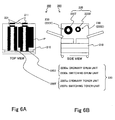
- Figs. 6A and 6B are a top view and a side view respectively showing the schematic structures of an image forming apparatus 200 according to a second embodiment.
- the image forming apparatus 200 is an apparatus for forming an image on a recording medium P such as a sheet as in a copying machine, a printer, a facsimile device, or the like.
- a recording medium P such as a sheet as in a copying machine, a printer, a facsimile device, or the like.
- a printing system an electro-photographic system is described as an example.
- the printing system may be another system such as an ink jet system.
- the image forming apparatus 200 includes an image forming apparatus main body 210 (refer it to as an apparatus main body, hereinafter) and a replaceable part 220 detachably attached to the apparatus main body 210.
- the apparatus main body 210 forms an image on a recording medium by using the replaceable part 220.
- the apparatus main body 210 is a substantially fixed component of the image forming apparatus 200.
- the apparatus main body 210 has an attaching section 230 to which the replaceable parts 220 are attachable.
- the replaceable part 220 is ordinarily a part which can be suitably replaced by another part when the part is exhausted.
- a toner unit 220T with which toner to be supplied is filled and a drum unit 220D in which a photosensitive drum, an charging device, and a cleaner are integrally formed are shown.
- the toner unit 220T and the drum unit 220D are respectively attached to attaching sections 230T and 230D to be attached.
- the number of the replaceable parts 220 may be one or three or more.
- the types of the replaceable parts 220 are not limited to specific types.
- a manufacturer of the apparatus main body 210 ordinarily assumes that the replaceable parts 220 (an approved part) whose use is permitted by the manufacturer, such as a genuine part or a recommended part, is attached to the apparatus main body and designs and produces the apparatus main body 210 so as to obtain desired image quality and a safety performance based on that condition.
- the replaceable part 220 (an unapproved part) whose use is not permitted by the manufacturer, such as a knock-off or unlicensed copy, etc. is attached to the apparatus main body 210 designed and produced as described above, an operation in this case is outside the range of an assumption of the manufacturer. Accordingly, various disadvantages may arise. For example, a problem concerning image quality, a malfunction, a failure of the apparatus main body 210, or tearing or wrinkling of the paper may occur.
- an operation mode of the apparatus main body 210 not only an inhibiting mode for inhibiting the use of the unapproved part, but also a permitting mode for permitting the use of the unapproved part is provided.
- the permitting mode in order to satisfy the desire of a user who wishes to use the unapproved part, while an image forming function is maintained, the functions of the image forming apparatus are restricted to avoid the disadvantages due to the use of the unapproved part. The contents of the inhibiting mode and the permitting mode will be described below.
- Fig. 7 is a block diagram showing the structure of the image forming apparatus 200 according to this embodiment.
- a unit memory 221 is provided as a nonvolatile storing medium.
- the operation mode switching information for switching the operation mode of the apparatus main body 210 is stored in a prescribed storing area 221a of the unit memory 221.
- the operation mode switching information may include information showing to which of multiple operation modes the operation mode is to be switched.
- information showing no switching is stored in the prescribed storing area 221a of the unit memory 221.
- the unit memory 221 preferably also serves as a memory for storing control information such as a correction value of unevenness in production or a using history.
- the unit memory 221 is a semiconductor memory included in an RFID (Radio Frequency Identification) tag to which data is read and from which data is written using waves.
- the unit memory 221 may be another type of storing medium such as a magnetic memory or an optical memory. Further, the unit memory 221 may be accessed by wire.
- the operation mode switching information is preferably written in the unit memory 221 by a special jig, a tool, or a writer to prevent the switching replaceable parts 220b from being copied or tampered with.
- the print engine 215 is a device for printing an image on the recording medium P in accordance with an electro-photographic process and includes a laser scanning optical system (ROS: Raster Output Scanner), a transfer device, a fixing device, various types of motors and a power circuit for applying a bias or supplying electric power to these devices or replaceable parts 220.
- ROS laser scanning optical system
- the controller 216 controls the overall operation of the image forming apparatus 200 and functions as an operation mode switching section for switching the operation mode.
- the controller 216 is a circuit board on which a CPU 216a, a ROM 216b, and a RAM 216c are mounted.
- a function for controlling the entire part of the image forming apparatus 200 or a function as the operation mode switching section is realized by executing a program stored in a storing medium such as the ROM 216b by the CPU 216a.
- Methods for realizing the above-described functions are not limited to specific methods. For example, the functions may be respectively realized by, for example, specialized hardware.
- a value "1" showing that the operation mode is to be switched to the permitting mode or a value "2" showing that the operation mode is to be switched to the inhibiting mode is stored as the operation mode switching information.
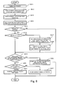
- the CPU 216a When the power of the image forming apparatus 200 is turned on (S211), the CPU 216a reads the operation mode information (the "inhibiting mode” or the “permitting mode") showing the current operation mode from the main body memory 214 (S212) and writes the read operation mode information in the RAM 216c (S213) .
- the operation mode information the "inhibiting mode” or the “permitting mode” showing the current operation mode from the main body memory 214 (S212) and writes the read operation mode information in the RAM 216c (S213) .
- the CPU 216a reads the value held in the storing area 221a of the unit memory 221 of the toner unit 220T through the reader/writer 211 (S214) .
- the value cannot be normally read S215: NO
- a process related to the switching operation of the operation mode cannot be carried out.
- the CPU 216a moves to step S219.
- the toner unit 220T may be possibly the unapproved part or a failure of a communication system may be exemplified.
- the CPU 216a decides whether or not the read value is "0" (S216) .
- the CPU 216a decides that the read value is "0" (S216: YES), that is, when the ordinary toner unit 220Ta is attached to the apparatus main body, the CPU 216a moves to the step S219. In this case, the operation mode is not switched and the current operation mode is maintained.
- CPU 216a decides that the read value is not "0" (S216: NO), that is, when the switching toner unit 220Tb is attached to the apparatus main body, the CPU 216a switches the operation mode in accordance with the read value (S217) Specifically, when the read value is "1", the CPU 216a rewrites the operation mode information held by the RAM 216c and the main body memory 214 to the "permitting mode". Thus, when the "inhibiting mode" is held in the main body memory 214, the inhibiting mode is switched to the permitting mode. When the "permitting mode" is held in the main body memory 214, consequently, the operation mode is not switched.
- the number of times of uses is limited to one time, however, may be limited to a prescribed number of plurality of times.
- the number of times of uses is written in, for example, the unit memory 221.
- the value of the storing area 221a may be set to "0".
- the number of times of uses is not necessarily limited and the step S218 may be omitted.
- step S219 the CPU 216a refers to the operation mode information held in the RAM 216c to decide whether or not the operation mode information is the "inhibiting mode".
- the CPU 216a determines whether or not an attached toner unit 220T is the approved part in accordance with a prescribed determining method (S220) . Specifically, the CPU 216a obtains information showing whether or not the toner unit 220T is the approved part from the toner unit 220T and determines whether or not the toner unit 220T is the approved part on the basis of the obtained information. For example, the CPU 216a reads encoded information previously stored in the unit memory 221 to discriminate whether or not the toner unit 220T is the approved part depending on whether or not the encoded information can be precisely decoded.
- the information showing whether or not the toner unit 220T is the approved part may be other information such as a hologram, not shown, attached to the toner unit 220T or the physical characteristic value of the toner unit 220T. Further, the method for determining whether or not the toner unit 220T is the approved part is not limited to a specific method.
- the CPU 216a controls the image forming apparatus 200 so as to operate under a preset unapproved part mode whether the attached toner unit 220T is the approved part or not (S223)
- the unapproved part mode in this embodiment is a control mode corresponding to a case that the unapproved part is attached to the apparatus main body as the toner unit 220T as in the first embodiment.
- the unapproved part mode to satisfy the desire of the user who wishes to use the unapproved part, while the image forming function of the image forming apparatus 200 is maintained, the functions of the image forming apparatus 200 realized in the approved part mode are restricted to avoid the disadvantages due to the use of the unapproved part.
- the CPU 216a obtains the attribute information of the replaceable parts from the replaceable parts 220 to control the print engine 215 on the basis of the attribute information. For example, the CPU 216a reads control information (a correction value or a counter value, etc.) from the unit memory 221 to determine various types of voltage, electric current, temperature, etc. for forming an image on the basis of the control information.
- control information a correction value or a counter value, etc.
- the attribute information of the replaceable parts 220 for example, bar code information attached to the replaceable parts 220 and the physical characteristic value of the replaceable parts 220 are exemplified as well as the control information stored in the unit memory 221.
- the CPU 216a controls the print engine 215 on the basis of information previously held in the apparatus main body 210 in place of the attribute information obtained from the replaceable part 220.
- the CPU 216a obtains the attribute information of the replaceable parts from the replaceable part 220 to realize prescribed functions by using the attribute information. For example, residual quantity information of toner is read from the unit memory 221 of the toner unit 220T to display a residual quantity of toner on the display of the UI 212 by using the residual quantity information of toner.
- the toner unit 220T When the toner unit 220T is the unapproved part, incorrect information may be possibly written in the unit memory 221. Therefore, when the residual quantity information of toner is read from the toner unit 220T of the unapproved part to display the residual quantity of toner on the basis thereof, incorrect information may be provided to the user.
- the approved part mode is set so that a prescribed quantity is obtained when the approved part is attached to the apparatus main body as the replaceable parts 220.
- various of parameters such as voltage, electric current, temperature, etc. in the approved part mode are set on the assumption that the replaceable part 220 satisfies prescribed characteristics (for example, withstand voltage, incombustibility, wear performance, etc.) as the approved part.
- the CPU 216a controls the print engine 215 so as to operate within an operation restricted range more strict than that of the approved part mode.
- upper limits and lower limits more strict than those of the approved part mode are set to various output values such as voltage, electric current, temperature, etc.
- the CPU 216a informs the user that the current operation mode is the unapproved part mode.
- the fact that the current operation mode is the unapproved part mode may be displayed on the display of the UI 212.
- the operation mode of the apparatus main body 210 is switched by attaching the replaceable parts 220.
- the operation mode can be switched by the same operation as an operation for replacing the ordinary replaceable parts 220a by another replaceable parts and a complicated operation is not required, an erroneous operation by the user can be prevented.
- the user when the user tries to switch the operation mode, the user must get the switching replaceable parts 220b from the manufacturer or the seller. Therefore, the degree of freedom for switching the operation mode by the user can be more restricted than when the operation mode is switched by the operation of the UI 212.
- this embodiment is preferably employed when a free switching operation by the user is not preferable.
- the manufacturer or the seller may deliver the switching replaceable parts 220b to the user. Therefore, a service man need not be dispatched to a place where the apparatus main body 210 is installed. Thus, a cost can be reduced.
- the manufacturer or seller delivers the switching replaceable parts 220b to the user, the manufacturer or seller can explain the user about the disadvantages or noticed items (for example, disadvantages due to the use of the unapproved part) due to the switching of the operation mode.
- replaceable part 220 two types of replaceable parts, including the switching replaceable parts 220b in which the operation mode switching information is stored and the ordinary replaceable part 220a that does not hold such information,are provided.
- the switching replaceable part 220b is attached to the apparatus main body 210
- the operation mode is switched.
- the ordinary replaceable part 220a is attached to the apparatus main body, the operation mode is not switched. Accordingly, when the ordinary replaceable part220a is used, the operation mode is not switched. Thus, the operation mode can be prevented from being unexpectedly switched.
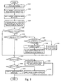
- Fig. 9 is a flowchart showing an operation procedure of an image forming apparatus 300 according to a third embodiment of the present invention. Because this embodiment is substantially the same as the second embodiment, to avoid duplication of description, components common to those of the second embodiment are designated using the same reference numerals and their description is not repeated.
- individual identifying information for identifying an apparatus main body 210 is assigned to the apparatus main body 210.
- an individual identifying number of the apparatus main body 210 is pre-stored in a ROM 216b of a controller 216 of the apparatus main body 210.
- the individual identifying number of the apparatus main body 210 whose operation mode is to be switched is previously held together with operation mode switching information .
- the individual identifying number is held in a prescribed storing area 221b of the unit memory 221.
- the individual identifying information is preferably written in the unit memory 221 by a special jig, a tool or a writer to prevent the switching replaceable part 220b from being copied or tampered with.
- the CPU 216a reads the individual identifying number held in the storing area 221b as well as a value held in a storing area 221a of the unit memory 221 of a toner unit 220T (S234).
- the CPU 216a decides whether or not the individual identifying number read from the storing area 221b of the unit memory 221 corresponds to the individual identifying number held in the ROM 216b (S237). That is, the CPU 216a decides whether or not the switching toner unit 220Tb attached to the apparatus main body 210 is a toner unit for the apparatus main body 210.
- a user A who desires to switch the operation mode from the inhibiting mode to the permitting mode communicates this desire to switch the operation mode to the manufacturer, submitting an individual identifying number #A of an apparatus main body 210A.
- the manufacturer writes the individual identifying number #A in the storing area 221b of the switching toner unit 220Tb, and then, sends the switching toner unit 220Tb to the user A.
- the user A attaches the received toner unit 220Tb to the apparatus main body 210A and turns on a power. Then, the operation mode of the apparatus main body 210A is switched from the inhibiting mode to the permitting mode.
- the user A or another user B attaches the toner unit 220Tb to another apparatus main body 210B, since the individual identifying numbers do not correspond to each other, the operation mode is not switched.
- the operation mode is switched.
- the apparatus main body 210 whose operation mode is switched by a certain switching replaceable parts 220b can be limited.
- the operation mode can be prevented from being unexpectedly switched.
- the manufacturer or seller can ascertain and manage each of the operation modes of multiple apparatus main bodies 210.
- Fig. 10 is a flowchart showing an operational procedure of an image forming apparatus 400 according to a fourth embodiment of the present invention.
- the current operationmode is the permitting mode
- communication with a unit memory 221 is not performed.
- parts common to those of the second or the third embodiment are designated by the same reference numerals and explanation thereof is not repeated.
- the CPU 216a When power of the image forming apparatus 400 is turned on (S251), the CPU 216a reads operation mode information (the "inhibiting mode” or the “permitting mode") showing the current operation mode from a main body memory 214 (S252) and writes the read operation mode information in a RAM 216c (S253).
- operation mode information the "inhibiting mode” or the “permitting mode” showing the current operation mode from a main body memory 214 (S252) and writes the read operation mode information in a RAM 216c (S253).
- the CPU 216a When the current operation mode is not the inhibiting mode (S254: NO), that is, the permitting mode, the CPU 216a does not communicate with the toner unit 220T. Then, the CPU 216a controls the image forming apparatus 400 so as to operate under a preset unapproved part mode whether the attached toner unit 220T is an approved part or not (S255).
- the CPU 216a determines whether or not the attached toner unit 220T is the approved part in accordance with a prescribed determining method (S256).
- the CPU 216a When the toner unit 220T is discriminated to be not the approved part (S256: NO), the CPU 216a inhibits an image forming operation by the image forming apparatus 400 to avoid disadvantages due to the use of an unapproved part (S257) . At this point, the CPU 216a preferably displays on the display of the UI 212 information indicating that the toner unit 220T of the unapproved part is attached to an apparatus main body to inform a user of the reason why the image forming function is stopped.
- the CPU 216a reads a value held in the storing area 221a of the unit memory 221 of the toner unit 220T and individual identifying information held in a storing area 221b through a reader/writer 211 (S258) . Then, the CPU 216a decides whether or not the read value is "0" (S259).
- the CPU 216a decides whether or not an individual identifying number read from the storing area 221b of the unit memory 221 corresponds to an individual identifying number held in a ROM 216b (S261).
- the CPU 216a decides that the individual identifying numbers do not correspond to each other (S261: NO)
- the CPU 216a does not switch the operation mode, performs a prescribed error process (S262) and controls the image forming apparatus 400 so as to operate under the approved part mode (S260).
- the CPU 216a decides that the individual identifying numbers correspond to each other (S261: YES), the CPU 216a switches the inhibiting mode to the permitting mode (S263) and performs a process for nullifying operation mode switching information held in the toner unit 220T (S264) . Then, the CPU 216a controls the image forming apparatus 400 so as to operate under the unapproved part mode (S255).
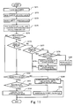
- Fig. 11 is a flowchart showing an operational procedure of an image forming apparatus 500 according to a fifth embodiment of the present invention. Because this embodiment is substantially the same as the second embodiment, to avoid the duplication of description, parts common to those of the second embodiment are designated with the same reference numerals and their explanation will not be repeated.
- drum unit 220D two types of units including an ordinary drum unit 220Da and a switching drum unit 220Db are provided.
- toner unit 220T two types of units including an ordinary toner unit 220Ta and a switching toner unit 220Tb are provided.
- a value "0" is stored as information showing no switching.
- a CPU 216a When the power of the image forming apparatus 500 is turned on (S271), a CPU 216a reads operation mode information (the "inhibiting mode” or the “permitting mode") showing a current operation mode from a main body memory 214 (S272) and writes the read operation mode information in a RAM 216c (S273).
- operation mode information the "inhibiting mode” or the “permitting mode” showing a current operation mode from a main body memory 214 (S272) and writes the read operation mode information in a RAM 216c (S273).
- the CPU 216a reads the value held in the storing area 221a of each of the unit memories 221 of the drum unit 220D and the toner unit 220T (S274) .
- the CPU 216a cannot normally read the value (S275: NO)
- the CPU 216a cannot perform a process related to the switching of the operation mode, so that the CPU 216a moves to step S282.
- the CPU 216a normally reads the value (S275: YES)
- the CPU 216a decides whether or not the value read from the drum unit 220D is "0" (S276).
- the CPU 216a decides that the value read from the storing area 221a of the drum unit 220D corresponds to the value read from the storing area 221a of the toner unit 220T (S278).
- the CPU 216a decides that the values correspond to each other (S278: YES)
- the CPU 216a switches the operation mode in accordance with the read value like the step S217 shown in Fig. 8 (S279).
- the CPU 216a performs a process for nullifying the operation mode switching information held in the drum unit 220D and the toner unit 220T like the step S218 shown in Fig. 8 (S280) and moves to the step S282.
- the CPU 216 decides that the values do not correspond to each other (S278: NO)
- the CPU 216a performs a prescribed error process, for example, the CPU 216a displays on a UI 212 that the values do not correspond to each other (S281) and moves to the step S282. In this case, the operation mode is not switched and the current operation mode is maintained.
- the CPU 216a refers to the operation mode information held in the RAM 216c to decide whether or not the operation mode information is the "inhibiting mode" (S282) .
- the CPU 216a determines that both the units are the approved parts (S283: YES)
- the CPU 216a controls the image forming apparatus 500 so as to operate under a preset approved part mode (S284) .
- the CPU 216a determines that at least one of the drum unit and the toner unit is not an approved part (S283: NO)
- the CPU 216a inhibits an image forming operation by the image forming apparatus 500 (S285).
- the ordinary replaceable parts 220a and the switching replaceable parts 220b are provided in the multiple types of replaceable parts 220.
- the operation mode is switched. Accordingly, a degree of freedom for switching the operation mode can be more restricted, and erroneous switching operation can be prevented with greater certainty.
- the operation mode is switched when the replaceable parts 220b for all of the multiple types of replaceable parts are attached to the apparatus main body, erroneous operation can be more reliably prevented.
- the degree of freedom for switching the operation mode can be increased, and while the degree of freedom for switching the operation mode is restricted, the operation mode can be simply switched.
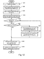
- Fig. 12 is a flowchart showing an operational procedure of an image forming apparatus 600 according to a sixth embodiment of the present invention.
- parts common to the second to the fifth embodiments are designated by the same reference numerals and their explanation will not be repeated.
- an operation mode (an inhibiting mode or a permitting mode) is set for each of a drum unit 220D and a toner unit 220T. Accordingly, in the drum unit 220D, the operation mode is switched between a drum inhibiting mode for inhibiting the use of an unapproved part and a drum permitting mode for permitting the use of an unapproved part. Further, in the toner unit 220T, the operation mode is switched between a toner inhibiting mode for inhibiting the use of an unapproved part and a toner permitting mode for permitting the use of an unapproved part.
- a value "1" showing that the operation mode is to be switched to the drum permitting mode, or a value “2" showing that the operation mode is to be switched to the drum inhibiting mode is stored.
- a value "1" showing that the operation mode is to be switched to the toner permitting mode, or a value "2" showing that the operation mode is to be switched to the toner inhibiting mode is stored.
- a CPU 216a when a power of the image forming apparatus 600 is turned on (S291), a CPU 216a reads operation mode information (the "drum inhibiting mode” or the “drum permitting mode", the “toner inhibiting mode” or the “toner permitting mode") showing a current operation mode from a main body memory 214 (S292) and writes the read operation mode information in a RAM 216c (S293).
- the CPU 216a reads a value held in the storing area 221a of the unit memory 221 of the drum unit 220D through a reader/writer 211 (S294).
- the CPU 216a cannot normally read the value (S295: NO)
- the CPU 216a since the CPU 216a cannot perform a process related to the switching of the operation mode, the CPU 216a moves to step S299.
- the CPU 216a normally reads the value (S295: YES)
- the CPU 216a decides whether or not the read value is "0" (S296).
- the CPU 216a decides that the read value is not "0" (S296: NO), that is, the switching drum unit 220Db is attached to the apparatus main body, the CPU 216a switches the operation mode in accordance with the read value (S297) . Specifically, when the read value is "1", the CPU 216a rewrites the operation mode information held in the RAM 216c and the main body memory 214 to the "drum permitting mode". Thus, when the "drum inhibiting mode" is held in the main body memory 214, the drum inhibiting mode is switched to the drum permitting mode. When the "drum permitting mode" is held in the main body memory 214, consequently, the operation mode is not switched for the drum unit 220D.
- the CPU 216a rewrites the operation mode information held in the RAM 216c and the main body memory 214 to the "drum inhibiting mode" .
- the drum permitting mode is switched to the drum inhibiting mode.
- the drum inhibiting mode is held in the main body memory 214, consequently, the operation mode is not switched for the drum unit 220D.
- the CPU 216a When the CPU 216 completes the switching process of the operation mode, the CPU 216a performs a process for nullifying operation mode switching information held in the drum unit 220D (S298). Specifically, the CPU 216a rewrites the value held in the prescribed storing area 221a of the unit memory 221 of the drum unit 220D to "0".
- step S299 the same processes as the steps S294 to 298 are carried out for the toner unit 220T.
- the apparatus main body 210 has multiple groups of operation modes composed of multiple operation modes.
- the apparatus main body has the group of operation modes including the drum inhibiting mode and the drum permitting mode and the group of operation modes including the toner inhibiting mode and the toner permitting mode. Then, the apparatus main body 210 switches the operation mode for each of the groups of operation modes in accordance with the operation mode switching information. Therefore, an optimum operation mode pattern suitable for various circumstances, such including user preferences, can be provided by a simple switching operation.
- the operation mode may be selectively switched between three or more operation modes. For example, when the operation mode is switched between an operation mode 1, an operation mode 2, ........., an operation mode N, in the storing area 221a of the switching replaceable parts 220b, "1", “2" toast and "N" showing that the operation mode is to be switched respectively to the operation modes may be held.
- the operation mode is not limited thereto.
- the operation mode may be switched among multiple operation modes in which accounting methods for a maintenance charge are mutually different.
- accounting methods for the maintenance charge as widely known, a method for counting the number of image forming sheets and charging based on the counted value, and a method that a maintenance charge is included in the price of the replaceable parts 220 may be exemplified.
Landscapes
- Physics & Mathematics (AREA)
- General Physics & Mathematics (AREA)
- Engineering & Computer Science (AREA)
- Computer Vision & Pattern Recognition (AREA)
- Life Sciences & Earth Sciences (AREA)
- Sustainable Development (AREA)
- Control Or Security For Electrophotography (AREA)
- Accessory Devices And Overall Control Thereof (AREA)
Abstract
Description
Claims (33)
- An image forming apparatus comprising:an image forming section to which a replaceable part is detachably attached; anda switching section that switches an operation mode of the image forming section to an approved part mode corresponding to a case wherein an approved part is attached as the replaceable part, and to an unapproved part mode corresponding to a case wherein a part other than the approved part is attached.
- The image forming apparatus according to claim 1, wherein, in the unapproved part mode, the image forming section maintains an image forming function, but restricts a function available in the approved part mode.
- The image forming apparatus according to claim 2, wherein the image forming section obtains attribute information of the replaceable part from the replaceable part and operates in accordance with the attribute information in the approved part mode, and operates in accordance with information previously stored in the image forming section in place of the attribute information in the unapproved part mode.
- The image forming apparatus according to claim 2, wherein the image forming section obtains attribute information of the replaceable part from the replaceable part and realizes a prescribed function by using the attribute information in the approved part mode, and disables the prescribed function in the unapproved part mode.
- The image forming apparatus according to claim 2, wherein, in the unapproved part mode, the image forming section operates within an operation limiting range stricter than that in the approved part mode.
- The image forming apparatus according to claim 1, wherein, in the unapproved part mode, the image forming section informs a user that a current operation mode is the unapproved part mode.
- The image forming apparatus according to claim 1, wherein, in the unapproved part mode, the image forming section obtains identifying information identifying a manufacturer name or a product name associated with the replaceable part and performs a preset operation associated with the manufacturer or product recognized from the identifying information.
- The image forming apparatus according to claim 7, wherein the image forming section obtains the identifying information from the replaceable part.
- The image forming apparatus according to claim 7, wherein, in the unapproved part mode, the image forming section obtains the attribute information of the replaceable part from the replaceable part and operates in accordance with the attribute information.
- The image forming apparatus according to claim 1, wherein the switching section switches the operation mode in accordance with a switching operation performed by the user.
- The image forming apparatus according to claim 1, wherein the switching section obtains information showing whether or not the replaceable part is an approved part from the replaceable part, uses the obtained information to determine whether or not the replaceable part is an approved part, and switches the operation mode in accordance with the results of the determination.
- A part detachable device comprising:an operating section to which a replaceable part is detachably attached; anda switching section that switches an operation mode of the operating section to an approved part mode corresponding to a case wherein an approved part is attached as the replaceable part and to an unapproved part mode corresponding to a case wherein a part other than the approved part is attached.
- The part detachable device according to claim 12, wherein, in the unapproved part mode, the operating section maintains a minimum functionalitybut restricts use of a function available in the approved part mode.
- The part detachable device according to claim 13, wherein the operating section obtains the attribute information of the replaceable part from the replaceable part and operates in accordance with the attribute information in the approved part mode, and operates on the basis of information previously stored in the operating section in place of the attribute information in the unapproved part mode.
- The part detachable device according to claim 13, wherein the operating section obtains the attribute information of the replaceable part from the replaceable part and realizes a prescribed function by using the attribute information in the approved part mode, and disables the prescribed function in the unapproved part mode.
- The part detachable device according to claim 13, wherein, in the unapproved part mode, the operating section operates within an operation limiting range stricter than that in the approved part mode.
- The part detachable device according to claim 12, wherein, in the unapproved part mode, the operating section informs a user that a current operation mode is the unapproved part mode.
- The part detachable device according to claim 12, wherein, in the unapproved part mode, the operating section obtains identifying information identifying a manufacturer name or a product name associated with the replaceable part and performs a preset operation associated with the manufacturer or product recognized from the identifying information.
- The part detachable device according to claim 18, wherein the operating section obtains the identifying information from the replaceable part.
- The part detachable device according to claim 18, wherein, in the unapproved part mode, the operating section obtains the attribute information of the replaceable part from the replaceable part and operates in accordance with the attribute information.
- The part detachable device according to claim 12, wherein the switching section switches the operation mode in accordance with a switching operation performed by the user.
- The part detachable device according to claim 12, wherein the switching section obtains information showing whether or not the replaceable part is an approved part from the replaceable part, determines whether or not the replaceable part is an approved part on the basis of the obtained information, and switches the operation mode in accordance with the determined result.
- An image forming apparatus for forming an image on a recording medium, the image forming apparatus comprising:an image forming apparatus main body having a plurality of operation modes anda replaceable part detachably attached to the image forming apparatus main body, wherein operation mode switching information for switching the operation modes of the image forming apparatus main body is stored in the replaceable part, and the image forming apparatus main body switches the operation modes in accordance with the operation mode switching information stored in the replaceable part when the replaceable part is attached.
- An image forming apparatus for forming an image on a recording medium, the image forming apparatus comprising:an image forming apparatus main body having a plurality of operation modes anda replaceable part detachably attached to the image forming apparatus main body, wherein the replaceable part is chosen from a set including at least two types of replaceable parts, including a switching replaceable part in which is pre-stored operation mode switching information for switching the operation mode of the image forming apparatus main body and an ordinary replaceable part that does not hold such information, and the image forming apparatus main body switches the operation mode on the basis of the operation mode switching information held by the replaceable part when the switching replaceable part is attached, and maintains a current operation mode when the ordinary replaceable part is attached.
- An image forming apparatus for forming an image on a recording medium, the image forming apparatus comprising:an image forming apparatus main body having a plurality of operation modes, anda plurality of replaceable parts detachably attached to the image forming apparatus main body, wherein each of the plurality of replaceable parts is chosen from a set comprising at least two types of replaceable parts, including switching replaceable parts in which is pre-stored operation mode switching information for switching the operation mode of the image forming apparatus main body and ordinary replaceable parts that do not hold such information, and ,when a plurality of the switching replaceable parts are attached in a prescribed combination, the image forming apparatus main body switches the operation mode on the basis of the operation mode switching information held by the replaceable parts, and otherwise maintains a current operation mode.
- The image forming apparatus according to claim 23, wherein when the image forming apparatus main body switches the operation mode in accordance with the operation mode switching information held by the replaceable part, the image forming apparatus main body nullifies the operation mode switching information stored in the replaceable part.
- The image forming apparatus according to claim 23, wherein in the replaceable part is pre-stored individual identifying information of the image forming apparatus main body whose operation mode is to be switched together with the operation mode switching information, and the image forming apparatus main body switches the operation mode when the individual identifying information held by the replaceable part corresponds to the individual identifying information of the image forming apparatus main body.
- The image forming apparatus according to claim23, wherein the operation mode switching information can be provided to the replaceable part only by using a special tool.
- The image forming apparatus according to claim 27, wherein the individual identifying information can be provided to the replaceable part only by using a special tool.
- The image forming apparatus according to claim 23, wherein the image forming apparatus main body has a plurality of groups of operation modes composed of a plurality of operation modes and switches the operation mode of each group of operation modes in accordance with the operation mode switching information.
- The image forming apparatus according to claim 23, wherein the image forming apparatus main body switches the operation mode between an inhibiting mode for inhibiting the use of the replaceable part whose use is not approved by a manufacturer and a permitting mode for permitting the use of the replaceable part.
- An image forming apparatus main body having a plurality of operation modes and which forms an image on a recording medium using a detachably attached replaceable part, the image forming apparatus main body comprising:an attaching section to which a replaceable part holding operation mode switching information for switching the operation modes can be attached, andan operation mode switching section that switches the operation mode on the basis of the operation mode switching information held by the replaceable part when the replaceable part is attached to the attaching section.
- An image forming apparatus main body having a plurality of operation modes and which forms an image on a recording medium using a detachably attached replaceable part, the image forming apparatus main body comprising:an attaching section to which at least two types of replaceable parts, including a switching replaceable part holding operation mode switching information for switching the operation modes and an ordinary replaceable part holding no such information can be attached andan operation mode switching section that switches the operation mode in accordance with the operation mode switching information held by the replaceable part when the switching replaceable part is attached to the attaching section, and maintains a current operation mode when the ordinary replaceable part is attached to the attaching section.
Priority Applications (1)
| Application Number | Priority Date | Filing Date | Title |
|---|---|---|---|
| EP08008127A EP1955862A1 (en) | 2004-04-30 | 2005-01-26 | Image forming apparatus and detachable part |
Applications Claiming Priority (4)
| Application Number | Priority Date | Filing Date | Title |
|---|---|---|---|
| JP2004135290 | 2004-04-30 | ||
| JP2004135290A JP2005316228A (en) | 2004-04-30 | 2004-04-30 | Image forming apparatus and component detachable apparatus |
| JP2004159082A JP4720109B2 (en) | 2004-05-28 | 2004-05-28 | Image forming apparatus |
| JP2004159082 | 2004-05-28 |
Related Child Applications (2)
| Application Number | Title | Priority Date | Filing Date |
|---|---|---|---|
| EP08008127A Division EP1955862A1 (en) | 2004-04-30 | 2005-01-26 | Image forming apparatus and detachable part |
| EP08008127.6 Division-Into | 2008-04-28 |
Publications (3)
| Publication Number | Publication Date |
|---|---|
| EP1591261A2 true EP1591261A2 (en) | 2005-11-02 |
| EP1591261A3 EP1591261A3 (en) | 2007-04-18 |
| EP1591261B1 EP1591261B1 (en) | 2011-03-16 |
Family
ID=34933453
Family Applications (2)
| Application Number | Title | Priority Date | Filing Date |
|---|---|---|---|
| EP08008127A Withdrawn EP1955862A1 (en) | 2004-04-30 | 2005-01-26 | Image forming apparatus and detachable part |
| EP05001565A Expired - Lifetime EP1591261B1 (en) | 2004-04-30 | 2005-01-26 | Image forming apparatus and detachable part |
Family Applications Before (1)
| Application Number | Title | Priority Date | Filing Date |
|---|---|---|---|
| EP08008127A Withdrawn EP1955862A1 (en) | 2004-04-30 | 2005-01-26 | Image forming apparatus and detachable part |
Country Status (4)
| Country | Link |
|---|---|
| US (1) | US7139494B2 (en) |
| EP (2) | EP1955862A1 (en) |
| KR (1) | KR100690533B1 (en) |
| DE (1) | DE602005026881D1 (en) |
Families Citing this family (23)
| Publication number | Priority date | Publication date | Assignee | Title |
|---|---|---|---|---|
| JP4378211B2 (en) * | 2004-04-28 | 2009-12-02 | キヤノン株式会社 | Image forming apparatus |
| JP2005326736A (en) * | 2004-05-17 | 2005-11-24 | Fuji Xerox Co Ltd | Image forming system having image forming apparatus provided with replacement unit |
| US7263298B2 (en) * | 2004-05-17 | 2007-08-28 | Fuji Xerox Co., Ltd. | Image forming apparatus mounted with replaceable unit, image forming system, and method of controlling image forming apparatus |
| JP4650780B2 (en) * | 2004-05-17 | 2011-03-16 | 富士ゼロックス株式会社 | Image forming apparatus equipped with replacement unit, image forming system, and method of controlling image forming apparatus |
| US7242873B2 (en) * | 2004-05-17 | 2007-07-10 | Fuji Xerox Co. Ltd. | Image forming apparatus mounted with replaceable unit, image forming system, and method of controlling image forming apparatus |
| JP4650781B2 (en) * | 2004-05-17 | 2011-03-16 | 富士ゼロックス株式会社 | Image forming apparatus equipped with an exchange unit |
| JP2007003658A (en) * | 2005-06-22 | 2007-01-11 | Konica Minolta Business Technologies Inc | Image forming apparatus |
| KR20070001635A (en) * | 2005-06-29 | 2007-01-04 | 삼성전자주식회사 | Developing cartridge and image forming apparatus having same |
| KR100717016B1 (en) * | 2005-07-27 | 2007-05-10 | 삼성전자주식회사 | Image forming apparatus control method and image forming apparatus |
| JP4577783B2 (en) * | 2006-04-25 | 2010-11-10 | 株式会社沖データ | Image forming apparatus |
| US7881632B2 (en) * | 2006-11-09 | 2011-02-01 | Kabushiki Kaisha Toshiba | Image forming apparatus for controlling fixing operation with auxiliary power source |
| JP4186126B2 (en) | 2006-12-26 | 2008-11-26 | ブラザー工業株式会社 | Image forming apparatus |
| DE102007020762A1 (en) * | 2007-05-03 | 2008-11-13 | OCé PRINTING SYSTEMS GMBH | Electrographic printing machine or photocopying machine, has photoconductor element, on which charge images are generated by images which are to be printed |
| US7995934B2 (en) * | 2007-09-20 | 2011-08-09 | Ricoh Company, Limited | Developing device, image forming apparatus, and process unit |
| WO2009055812A1 (en) * | 2007-10-25 | 2009-04-30 | Futurelogic, Inc. | Modular transaction printer |
| US20110058201A1 (en) * | 2009-09-08 | 2011-03-10 | Xerox Corporation | Method and apparatus for identifying parts in an image production device |
| JP5736238B2 (en) * | 2011-05-30 | 2015-06-17 | Hoya株式会社 | Operation protection device, operation protection software, and operation protection method |
| US8890672B2 (en) | 2011-08-29 | 2014-11-18 | Harnischfeger Technologies, Inc. | Metal tooth detection and locating |
| JP6478486B2 (en) * | 2013-11-20 | 2019-03-06 | キヤノン株式会社 | Information processing apparatus, control method thereof, and program |
| US9611625B2 (en) | 2015-05-22 | 2017-04-04 | Harnischfeger Technologies, Inc. | Industrial machine component detection and performance control |
| CA3263786A1 (en) | 2015-11-12 | 2025-03-24 | Joy Global Surface Mining Inc | Methods and systems for detecting heavy machine wear |
| KR102390147B1 (en) * | 2018-08-30 | 2022-04-25 | 휴렛-팩커드 디벨롭먼트 컴퍼니, 엘.피. | Toner refill cartridge connected to main body through interface between development cartridge and main body |
| JP7728521B2 (en) | 2021-09-28 | 2025-08-25 | ブラザー工業株式会社 | Recording device, consumables for recording device, and information processing method |
Family Cites Families (13)
| Publication number | Priority date | Publication date | Assignee | Title |
|---|---|---|---|---|
| JP2666930B2 (en) | 1987-08-28 | 1997-10-22 | 株式会社東芝 | Image forming device |
| JPH01200272A (en) | 1988-02-03 | 1989-08-11 | Fuji Xerox Co Ltd | Identifying device for cartridge provided with photosensitive body |
| JP3413052B2 (en) | 1996-04-23 | 2003-06-03 | キヤノン株式会社 | Ink jet recording apparatus and control method |
| US6158837A (en) * | 1997-09-19 | 2000-12-12 | Xerox Corporation | Printer having print mode for non-qualified marking material |
| JP4274332B2 (en) | 1998-02-20 | 2009-06-03 | 東芝テック株式会社 | Image forming apparatus |
| JP3476704B2 (en) * | 1999-03-30 | 2003-12-10 | シャープ株式会社 | Image forming device |
| JP2002006702A (en) * | 2000-06-26 | 2002-01-11 | Konica Corp | Image forming apparatus, method of controlling image forming apparatus, method of managing image forming apparatus |
| JP2002244370A (en) * | 2000-11-16 | 2002-08-30 | Canon Inc | Image forming apparatus and method, process cartridge |
| JP2002331686A (en) | 2001-05-09 | 2002-11-19 | Toppan Printing Co Ltd | Consumables, equipment main body, equipment, module, method of manufacturing consumables, and method of determining consumables. |
| US6678482B2 (en) | 2001-09-17 | 2004-01-13 | Sharp Kabushiki Kaisha | Image forming apparatus and method for determining suitability of replaceable component |
| JP2003145735A (en) * | 2001-11-09 | 2003-05-21 | Canon Inc | Printing apparatus, printing system, and printing method |
| JP2003285520A (en) | 2002-03-27 | 2003-10-07 | Brother Ind Ltd | Printing equipment |
| US7296873B2 (en) * | 2003-10-08 | 2007-11-20 | Konica Minolta Business Technologies, Inc. | Printing device, printing method, printing program and computer-readable recording medium on which the program is recorded |
-
2005
- 2005-01-24 US US11/040,014 patent/US7139494B2/en not_active Expired - Lifetime
- 2005-01-26 EP EP08008127A patent/EP1955862A1/en not_active Withdrawn
- 2005-01-26 DE DE602005026881T patent/DE602005026881D1/en not_active Expired - Lifetime
- 2005-01-26 EP EP05001565A patent/EP1591261B1/en not_active Expired - Lifetime
- 2005-02-23 KR KR1020050014820A patent/KR100690533B1/en not_active Expired - Lifetime
Non-Patent Citations (1)
| Title |
|---|
| None |
Also Published As
| Publication number | Publication date |
|---|---|
| DE602005026881D1 (en) | 2011-04-28 |
| EP1591261B1 (en) | 2011-03-16 |
| KR20060043108A (en) | 2006-05-15 |
| EP1955862A1 (en) | 2008-08-13 |
| EP1591261A3 (en) | 2007-04-18 |
| US7139494B2 (en) | 2006-11-21 |
| KR100690533B1 (en) | 2007-03-09 |
| US20050244170A1 (en) | 2005-11-03 |
Similar Documents
| Publication | Publication Date | Title |
|---|---|---|
| EP1591261B1 (en) | Image forming apparatus and detachable part | |
| US7031623B2 (en) | Image forming apparatus, management method for replacement part used therefor, and management program for replacement part | |
| US7657193B2 (en) | Consumable management device, image forming apparatus, computer readable medium storing a program, and consumable management method | |
| US8036546B2 (en) | Abnormal sound diagnostic apparatus, abnormal sound diagnostic method, recording medium storing abnormal sound diagnostic program and data signal | |
| JP4366613B2 (en) | Image forming apparatus and image forming apparatus setting method | |
| JP2005316229A (en) | Parts discrimination apparatus, parts detachable apparatus, and image forming apparatus | |
| EP0509530B1 (en) | Communication apparatus and method | |
| US7286775B2 (en) | Image formation device enabling switching display of remaining developing agent in monochrome printing mode | |
| US9137409B2 (en) | Electronic apparatus and image forming apparatus | |
| CN100489675C (en) | Image forming apparatus, part detaching device and image forming apparatus main body | |
| JP2005053077A (en) | Image forming apparatus and control method in the apparatus | |
| JP4720109B2 (en) | Image forming apparatus | |
| JP4047017B2 (en) | Image forming apparatus | |
| US7317880B2 (en) | Image forming device for controlling density adjustment based on a type of development unit | |
| JP4840576B2 (en) | Image forming apparatus | |
| JP2011175181A (en) | Image forming apparatus | |
| US20060176514A1 (en) | Image forming device and firmware overwriting method | |
| JP2009008757A (en) | Image forming apparatus, print control method for the apparatus and print control program | |
| US7532827B2 (en) | Image-forming apparatus | |
| JP7782190B2 (en) | Image forming apparatus and determination method | |
| JP2005195900A (en) | Image forming apparatus and image forming method | |
| JP2001296775A (en) | Image forming device | |
| JP2005115157A (en) | Image forming apparatus, unit of the image forming apparatus and information controlling method of the image forming apparatus | |
| US7206529B2 (en) | Image forming apparatus and control method for the same | |
| JP2005292771A (en) | Image forming apparatus |
Legal Events
| Date | Code | Title | Description |
|---|---|---|---|
| PUAI | Public reference made under article 153(3) epc to a published international application that has entered the european phase |
Free format text: ORIGINAL CODE: 0009012 |
|
| 17P | Request for examination filed |
Effective date: 20050223 |
|
| AK | Designated contracting states |
Kind code of ref document: A2 Designated state(s): AT BE BG CH CY CZ DE DK EE ES FI FR GB GR HU IE IS IT LI LT LU MC NL PL PT RO SE SI SK TR |
|
| AX | Request for extension of the european patent |
Extension state: AL BA HR LV MK YU |
|
| PUAL | Search report despatched |
Free format text: ORIGINAL CODE: 0009013 |
|
| AK | Designated contracting states |
Kind code of ref document: A3 Designated state(s): AT BE BG CH CY CZ DE DK EE ES FI FR GB GR HU IE IS IT LI LT LU MC NL PL PT RO SE SI SK TR |
|
| AX | Request for extension of the european patent |
Extension state: AL BA HR LV MK YU |
|
| RIC1 | Information provided on ipc code assigned before grant |
Ipc: G03G 15/00 20060101ALI20070313BHEP Ipc: B41J 29/393 20060101AFI20050801BHEP Ipc: B41J 2/175 20060101ALI20070313BHEP |
|
| 17Q | First examination report despatched |
Effective date: 20071102 |
|
| AKX | Designation fees paid |
Designated state(s): DE FR GB |
|
| GRAP | Despatch of communication of intention to grant a patent |
Free format text: ORIGINAL CODE: EPIDOSNIGR1 |
|
| GRAS | Grant fee paid |
Free format text: ORIGINAL CODE: EPIDOSNIGR3 |
|
| GRAL | Information related to payment of fee for publishing/printing deleted |
Free format text: ORIGINAL CODE: EPIDOSDIGR3 |
|
| GRAS | Grant fee paid |
Free format text: ORIGINAL CODE: EPIDOSNIGR3 |
|
| GRAA | (expected) grant |
Free format text: ORIGINAL CODE: 0009210 |
|
| AK | Designated contracting states |
Kind code of ref document: B1 Designated state(s): DE FR GB |
|
| REG | Reference to a national code |
Ref country code: GB Ref legal event code: FG4D |
|
| REF | Corresponds to: |
Ref document number: 602005026881 Country of ref document: DE Date of ref document: 20110428 Kind code of ref document: P |
|
| REG | Reference to a national code |
Ref country code: DE Ref legal event code: R096 Ref document number: 602005026881 Country of ref document: DE Effective date: 20110428 |
|
| PLBE | No opposition filed within time limit |
Free format text: ORIGINAL CODE: 0009261 |
|
| STAA | Information on the status of an ep patent application or granted ep patent |
Free format text: STATUS: NO OPPOSITION FILED WITHIN TIME LIMIT |
|
| 26N | No opposition filed |
Effective date: 20111219 |
|
| REG | Reference to a national code |
Ref country code: DE Ref legal event code: R097 Ref document number: 602005026881 Country of ref document: DE Effective date: 20111219 |
|
| REG | Reference to a national code |
Ref country code: FR Ref legal event code: PLFP Year of fee payment: 12 |
|
| REG | Reference to a national code |
Ref country code: FR Ref legal event code: PLFP Year of fee payment: 13 |
|
| REG | Reference to a national code |
Ref country code: FR Ref legal event code: PLFP Year of fee payment: 14 |
|
| REG | Reference to a national code |
Ref country code: DE Ref legal event code: R082 Ref document number: 602005026881 Country of ref document: DE Representative=s name: WUNDERLICH & HEIM PATENTANWAELTE PARTNERSCHAFT, DE |
|
| REG | Reference to a national code |
Ref country code: DE Ref legal event code: R081 Ref document number: 602005026881 Country of ref document: DE Owner name: FUJIFILM BUSINESS INNOVATION CORP., JP Free format text: FORMER OWNER: FUJI XEROX CO., LTD., TOKYO, JP |
|
| P01 | Opt-out of the competence of the unified patent court (upc) registered |
Effective date: 20230512 |
|
| PGFP | Annual fee paid to national office [announced via postgrant information from national office to epo] |
Ref country code: GB Payment date: 20231207 Year of fee payment: 20 |
|
| PGFP | Annual fee paid to national office [announced via postgrant information from national office to epo] |
Ref country code: FR Payment date: 20231212 Year of fee payment: 20 |
|
| PGFP | Annual fee paid to national office [announced via postgrant information from national office to epo] |
Ref country code: DE Payment date: 20231128 Year of fee payment: 20 |
|
| REG | Reference to a national code |
Ref country code: DE Ref legal event code: R071 Ref document number: 602005026881 Country of ref document: DE |
|
| REG | Reference to a national code |
Ref country code: GB Ref legal event code: PE20 Expiry date: 20250125 |
|
| PG25 | Lapsed in a contracting state [announced via postgrant information from national office to epo] |
Ref country code: GB Free format text: LAPSE BECAUSE OF EXPIRATION OF PROTECTION Effective date: 20250125 |