EP1591075B1 - Procédé et dispositif pour la préparation d'un implant de genou - Google Patents
Procédé et dispositif pour la préparation d'un implant de genou Download PDFInfo
- Publication number
- EP1591075B1 EP1591075B1 EP04009937A EP04009937A EP1591075B1 EP 1591075 B1 EP1591075 B1 EP 1591075B1 EP 04009937 A EP04009937 A EP 04009937A EP 04009937 A EP04009937 A EP 04009937A EP 1591075 B1 EP1591075 B1 EP 1591075B1
- Authority
- EP
- European Patent Office
- Prior art keywords
- planning
- anatomy
- genicular
- patella
- data
- Prior art date
- Legal status (The legal status is an assumption and is not a legal conclusion. Google has not performed a legal analysis and makes no representation as to the accuracy of the status listed.)
- Expired - Lifetime
Links
- 239000007943 implant Substances 0.000 title claims description 54
- 210000003127 knee Anatomy 0.000 title claims description 31
- 238000000034 method Methods 0.000 title claims description 26
- 210000004417 patella Anatomy 0.000 claims description 41
- 210000000689 upper leg Anatomy 0.000 claims description 23
- 210000002303 tibia Anatomy 0.000 claims description 10
- 210000003041 ligament Anatomy 0.000 claims description 4
- 206010061068 Congenital knee deformity Diseases 0.000 claims description 2
- 239000003086 colorant Substances 0.000 claims description 2
- 238000002591 computed tomography Methods 0.000 claims description 2
- 238000003384 imaging method Methods 0.000 claims description 2
- 210000003484 anatomy Anatomy 0.000 claims 13
- 238000004590 computer program Methods 0.000 claims 1
- 210000000988 bone and bone Anatomy 0.000 description 17
- 239000003550 marker Substances 0.000 description 6
- 238000002513 implantation Methods 0.000 description 5
- 230000006978 adaptation Effects 0.000 description 3
- 238000012937 correction Methods 0.000 description 3
- 230000002980 postoperative effect Effects 0.000 description 3
- 238000001514 detection method Methods 0.000 description 2
- 210000000629 knee joint Anatomy 0.000 description 2
- 210000002414 leg Anatomy 0.000 description 2
- 238000003491 array Methods 0.000 description 1
- 230000002349 favourable effect Effects 0.000 description 1
- 230000008058 pain sensation Effects 0.000 description 1
- 230000037361 pathway Effects 0.000 description 1
- 238000009877 rendering Methods 0.000 description 1
- 239000000523 sample Substances 0.000 description 1
- 238000004088 simulation Methods 0.000 description 1
Images

Classifications
-
- A—HUMAN NECESSITIES
- A61—MEDICAL OR VETERINARY SCIENCE; HYGIENE
- A61B—DIAGNOSIS; SURGERY; IDENTIFICATION
- A61B5/00—Measuring for diagnostic purposes; Identification of persons
- A61B5/45—For evaluating or diagnosing the musculoskeletal system or teeth
- A61B5/4538—Evaluating a particular part of the muscoloskeletal system or a particular medical condition
- A61B5/4585—Evaluating the knee
-
- A—HUMAN NECESSITIES
- A61—MEDICAL OR VETERINARY SCIENCE; HYGIENE
- A61B—DIAGNOSIS; SURGERY; IDENTIFICATION
- A61B34/00—Computer-aided surgery; Manipulators or robots specially adapted for use in surgery
- A61B34/10—Computer-aided planning, simulation or modelling of surgical operations
-
- A—HUMAN NECESSITIES
- A61—MEDICAL OR VETERINARY SCIENCE; HYGIENE
- A61B—DIAGNOSIS; SURGERY; IDENTIFICATION
- A61B5/00—Measuring for diagnostic purposes; Identification of persons
- A61B5/103—Detecting, measuring or recording devices for testing the shape, pattern, colour, size or movement of the body or parts thereof, for diagnostic purposes
- A61B5/107—Measuring physical dimensions, e.g. size of the entire body or parts thereof
- A61B5/1076—Measuring physical dimensions, e.g. size of the entire body or parts thereof for measuring dimensions inside body cavities, e.g. using catheters
-
- A—HUMAN NECESSITIES
- A61—MEDICAL OR VETERINARY SCIENCE; HYGIENE
- A61B—DIAGNOSIS; SURGERY; IDENTIFICATION
- A61B5/00—Measuring for diagnostic purposes; Identification of persons
- A61B5/103—Detecting, measuring or recording devices for testing the shape, pattern, colour, size or movement of the body or parts thereof, for diagnostic purposes
- A61B5/11—Measuring movement of the entire body or parts thereof, e.g. head or hand tremor, mobility of a limb
- A61B5/1113—Local tracking of patients, e.g. in a hospital or private home
- A61B5/1114—Tracking parts of the body
-
- A—HUMAN NECESSITIES
- A61—MEDICAL OR VETERINARY SCIENCE; HYGIENE
- A61B—DIAGNOSIS; SURGERY; IDENTIFICATION
- A61B5/00—Measuring for diagnostic purposes; Identification of persons
- A61B5/103—Detecting, measuring or recording devices for testing the shape, pattern, colour, size or movement of the body or parts thereof, for diagnostic purposes
- A61B5/11—Measuring movement of the entire body or parts thereof, e.g. head or hand tremor, mobility of a limb
- A61B5/1126—Measuring movement of the entire body or parts thereof, e.g. head or hand tremor, mobility of a limb using a particular sensing technique
- A61B5/1127—Measuring movement of the entire body or parts thereof, e.g. head or hand tremor, mobility of a limb using a particular sensing technique using markers
-
- A—HUMAN NECESSITIES
- A61—MEDICAL OR VETERINARY SCIENCE; HYGIENE
- A61B—DIAGNOSIS; SURGERY; IDENTIFICATION
- A61B90/00—Instruments, implements or accessories specially adapted for surgery or diagnosis and not covered by any of the groups A61B1/00 - A61B50/00, e.g. for luxation treatment or for protecting wound edges
- A61B90/36—Image-producing devices or illumination devices not otherwise provided for
-
- A—HUMAN NECESSITIES
- A61—MEDICAL OR VETERINARY SCIENCE; HYGIENE
- A61B—DIAGNOSIS; SURGERY; IDENTIFICATION
- A61B34/00—Computer-aided surgery; Manipulators or robots specially adapted for use in surgery
- A61B34/10—Computer-aided planning, simulation or modelling of surgical operations
- A61B2034/101—Computer-aided simulation of surgical operations
- A61B2034/102—Modelling of surgical devices, implants or prosthesis
-
- A—HUMAN NECESSITIES
- A61—MEDICAL OR VETERINARY SCIENCE; HYGIENE
- A61B—DIAGNOSIS; SURGERY; IDENTIFICATION
- A61B34/00—Computer-aided surgery; Manipulators or robots specially adapted for use in surgery
- A61B34/10—Computer-aided planning, simulation or modelling of surgical operations
- A61B2034/101—Computer-aided simulation of surgical operations
- A61B2034/105—Modelling of the patient, e.g. for ligaments or bones
-
- A—HUMAN NECESSITIES
- A61—MEDICAL OR VETERINARY SCIENCE; HYGIENE
- A61B—DIAGNOSIS; SURGERY; IDENTIFICATION
- A61B34/00—Computer-aided surgery; Manipulators or robots specially adapted for use in surgery
- A61B34/10—Computer-aided planning, simulation or modelling of surgical operations
- A61B2034/107—Visualisation of planned trajectories or target regions
-
- A—HUMAN NECESSITIES
- A61—MEDICAL OR VETERINARY SCIENCE; HYGIENE
- A61B—DIAGNOSIS; SURGERY; IDENTIFICATION
- A61B34/00—Computer-aided surgery; Manipulators or robots specially adapted for use in surgery
- A61B34/20—Surgical navigation systems; Devices for tracking or guiding surgical instruments, e.g. for frameless stereotaxis
- A61B2034/2046—Tracking techniques
- A61B2034/2051—Electromagnetic tracking systems
-
- A—HUMAN NECESSITIES
- A61—MEDICAL OR VETERINARY SCIENCE; HYGIENE
- A61B—DIAGNOSIS; SURGERY; IDENTIFICATION
- A61B34/00—Computer-aided surgery; Manipulators or robots specially adapted for use in surgery
- A61B34/20—Surgical navigation systems; Devices for tracking or guiding surgical instruments, e.g. for frameless stereotaxis
- A61B2034/2046—Tracking techniques
- A61B2034/2055—Optical tracking systems
-
- A—HUMAN NECESSITIES
- A61—MEDICAL OR VETERINARY SCIENCE; HYGIENE
- A61B—DIAGNOSIS; SURGERY; IDENTIFICATION
- A61B34/00—Computer-aided surgery; Manipulators or robots specially adapted for use in surgery
- A61B34/20—Surgical navigation systems; Devices for tracking or guiding surgical instruments, e.g. for frameless stereotaxis
- A61B2034/2068—Surgical navigation systems; Devices for tracking or guiding surgical instruments, e.g. for frameless stereotaxis using pointers, e.g. pointers having reference marks for determining coordinates of body points
-
- A—HUMAN NECESSITIES
- A61—MEDICAL OR VETERINARY SCIENCE; HYGIENE
- A61B—DIAGNOSIS; SURGERY; IDENTIFICATION
- A61B34/00—Computer-aided surgery; Manipulators or robots specially adapted for use in surgery
- A61B34/25—User interfaces for surgical systems
- A61B2034/252—User interfaces for surgical systems indicating steps of a surgical procedure
-
- A—HUMAN NECESSITIES
- A61—MEDICAL OR VETERINARY SCIENCE; HYGIENE
- A61B—DIAGNOSIS; SURGERY; IDENTIFICATION
- A61B90/00—Instruments, implements or accessories specially adapted for surgery or diagnosis and not covered by any of the groups A61B1/00 - A61B50/00, e.g. for luxation treatment or for protecting wound edges
- A61B90/36—Image-producing devices or illumination devices not otherwise provided for
- A61B90/37—Surgical systems with images on a monitor during operation
- A61B2090/376—Surgical systems with images on a monitor during operation using X-rays, e.g. fluoroscopy
-
- A—HUMAN NECESSITIES
- A61—MEDICAL OR VETERINARY SCIENCE; HYGIENE
- A61B—DIAGNOSIS; SURGERY; IDENTIFICATION
- A61B34/00—Computer-aided surgery; Manipulators or robots specially adapted for use in surgery
- A61B34/20—Surgical navigation systems; Devices for tracking or guiding surgical instruments, e.g. for frameless stereotaxis
-
- A—HUMAN NECESSITIES
- A61—MEDICAL OR VETERINARY SCIENCE; HYGIENE
- A61B—DIAGNOSIS; SURGERY; IDENTIFICATION
- A61B34/00—Computer-aided surgery; Manipulators or robots specially adapted for use in surgery
- A61B34/25—User interfaces for surgical systems
-
- A—HUMAN NECESSITIES
- A61—MEDICAL OR VETERINARY SCIENCE; HYGIENE
- A61B—DIAGNOSIS; SURGERY; IDENTIFICATION
- A61B5/00—Measuring for diagnostic purposes; Identification of persons
- A61B5/45—For evaluating or diagnosing the musculoskeletal system or teeth
- A61B5/4528—Joints
Definitions
- the invention relates to a planning method and a planning device for knee implantation.
- an implant When placing knee implants, an implant should be attached to the remaining bone in such a way that no excessive or unilaterally high loads occur later during the movement, which can lead to a sensation of pain.
- patella tracking In order to take these boundary conditions into account in the planning of the implantation, so-called patella tracking is already conventionally carried out in a very simple design.
- tracking or “motion-capturing” in the present text, it refers to the tracking of the movement of a body with the aid of motion detection devices.
- active radiator or passive reflectors can be tracked or tracked to detect their whereabouts at a given time (pre- / intra- / post-operative) or their trajectory and thus the place or to be able to determine the path of the body.
- passive marker reflectors that emit infrared light that is detected by two infrared light cameras, wherein spatial locations or spatial movements of the body can be determined by stereoscopic viewing.
- reference arrays (arrangements of, for example, three of the above-mentioned markers) are attached to this as well as the femur and possibly also tibial bone, all three bones are registered, and one track is tracked or just a few single points of the patella to detect their orbit opposite the femur bone.
- a method is to be provided which allows for optimal planning and thus also provides for the position and path of the patella after placing the implant for favorable conditions.
- the advantages of the present invention are based on the fact that the patient's knee anatomy is detected spatially or the surface contour, so that touches or overlaps between the implant and the parts of the knee anatomy can be detected and simulated much more extensively and with much greater significance. Based on these results, a possible problem with a currently proposed implant positioning can be detected much more precisely than before, and the positioning can be adjusted until the problem no longer occurs.
- the invention is also part of the patella tracking functionality of a surgical computer-aided planning system.
- the general idea is also to follow the movement of the patella towards the femur bone, whereby as a postoperative result the patella or a patellar implant should slide in such a way on the femur or on the femoral implant that the patient at the posterior or anterior part of the patella no Feeling pain.
- This result can be achieved by ensuring that the patella runs anatomically after implantation and does not place unnatural stresses on the patella be applied. This is true even if the patella sliding surface has been replaced by an implant.
- the spatial data of the shape of the patient's knee anatomy are detected by a surface scan by means of a tracked scanning instrument, in particular by means of a navigated pointer of a surgical navigation system.
- a surface scan by means of a tracked scanning instrument, in particular by means of a navigated pointer of a surgical navigation system.
- Such an embodiment makes the whole environment very simple and clear and eliminates the need for complicated and expensive surface scanning apparatus. It is particularly advantageous in such scans, when those areas of the patient knee anatomy are scanned or detected, which later also touch or run against each other or have contact, so the contact or running surfaces of the knee anatomy parts.
- the scans may be performed pre-operatively or intraoperatively.
- the movement recording can also be post-operative, if, for example, an implanted reference marker remains in the said bone of the patient and is measured, for example, in a magnetic field. If the position of the reference marker to the bone image is known, such as by an intraoperatively performed referencing, the recorded movement can be compared with the pre- or intraoperatively recorded movements and analyzed.
- the touches or overlaps are considered to be uncritical if they indicate substantially symmetrical contacts between the parts of the knee anatomy or avoidance of patella alta or patella bacha.
- the adaptation of the positioning, the shape or orientation of the implant according to the invention can be done automatically by the computer-aided planning system. This is not the only option. Rather, it is also possible according to the invention to have the computer-aided planning system output data on at least one possible adaptation, wherein the suitable adaptation can then be confirmed or selected by operator input. A third option is then an adjustment by the operator based on the acquired touch or crossover data.
- One or more of these illustrated bodies may be included in the image output.
- a variety of display options are conceivable, for example, the detected touch or overlap data monochrome, monochrome with different shades or different colors, depending on the intensity of the touch or
- the method according to the invention is also suitable in those cases where band corrections take place.
- the change in patellar movement can be determined after a knee length correction and optionally taken into account in the adjustment.
- the movement of the patella in the original state of the knee joint is recorded when the knee is flexed and stretched.
- This can be done pre- and / or intraoperatively, with reference marker arrangements being placed on the patella and on the articular ends of the femur and tibia and followed by a camera-based or magnetic tracking system, for example.
- a camera-based or magnetic tracking system for example.
- Shape after being captured This happens here, for example, in that the surfaces are traversed with the tip of a likewise tracked Abtastinstruments, so that in the planning system, the outer contour can be stored in terms of area as a record. Now, the planning system knows the natural movement between the patella and the remaining joint parts with each other, and it knows the shape of the touching and running surfaces in this anatomical state.
- the planning system also includes data for knee implants, particularly data on the shape of such knee implants. If, at the planning station, virtually a part of the knee anatomy, for example of the femoral condyle, is replaced by such a knee implant, e.g.
- the contact or walking surfaces can be calculated from the resulting touches or overlaps and highlighted in an image to provide the surgeon with information about how the position of the implant affects the tension and kinematics of the patella , In other words, the recorded movement of the patella is represented, for example, in an implant positioning planning view with respect to the femur bone and a planned femur implant position.
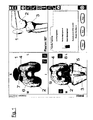
- FIG. 1 (and in FIG. 2 1) denotes the patella, the reference numeral 2 the femur bone and the reference numeral 3 the tibia.
- FIG. 1 denotes the patella
- the reference numeral 2 the femur bone
- the reference numeral 3 the tibia.
- right above an angular position of the knee joint is shown in a side view, including one input / output field of the software.
- the image shows the femur bone with patella and in FIG. 1
- the lower left shows the femur and tibia with implants.
- the image on the top right also shows the femoral implant.
- FIG. 1 Left top in FIG. 1 the position of the patella 1 over the femur bone 2 is shown.
- an implant 4 is arranged on the femur 2, on the femur 2, an implant 4 is arranged.
- On the implant 4 as well as on the patella is indicated by different shading, where a strong contact (impingement) and where a weaker contact takes place, when the knee is moved with the implant set.
- the darker areas indicate, as in the legend is shown on the lower right, a stronger touch or a stronger contact than the brighter places; a dark spot on the femoral implant is designated by the reference numeral 6, a bright spot on the patella by the reference numeral 7.
- the positioning of the implant can now be virtually adapted, for example by a virtual displacement to the anterior or posterior, medial or lateral, or in a rotation. This can be done automatically due to the contact strength information provided by the planning system or "by hand" through user intervention. At the end, one will find an implant position where the contact intensities are within a desired range.
- the contact intensity may here be e.g. a pressure and / or the direction of pressure on the patella.
- the intensity can e.g. be determined selectively, over an area or volume-related.
- FIG. 2 shows illustrations for a specific application in the context of the present invention. Namely, during the operation, a change in the kinematics or leg axis, in particular z. As an extension of the knee ligaments, is also expected that the career of the patella changes. To account for these changes in position of the patella, the user of the system according to the invention after the changes to the ligaments can again record the movement of the parts of the knee anatomy by means of the tracking or motion capturing method and make these data available to the planning station. When a movement sequence is simulated again, it becomes clear how the position and trajectory of the patella changes, what in FIG. 2 at the bottom left, the reference numeral 1 'indicating the original and the reference numeral 1 the new position of the patella after the band extension.
- arrows and text indicate how the situation has changed, such as a shift of 4.5 mm to the left, 3.2 mm to the top, and a rotation of 2 ° to the opposite clockwise.
- the operator can then choose whether to select the initial or the current new pathway as the basis for the implant positioning. Then again the contact intensity is shown (see FIG. 1 ) and the optimal implant position is determined.
- the determined planning data can be used to determine the positioning of a device (gauge) with the aid of which the bones are removed so that the actual implant can be placed and fastened in the optimal position.
- the motion recording can be done post-operatively again, for example, if an implanted reference marker remains in the patient's bones, e.g. measured in a magnetic field. If the position of the reference marker to the bone image is known, such as by a referencing performed intraoperatively, the recorded movement can be compared with the pre- or intraoperatively recorded movements and analyzed.
Claims (13)
- Procédé de conception pour implants du genou, dans lequel- on relève des données spatiales ou des données du contour superficiel de la forme d'une anatomie du genou d'un patient, à savoir d'au moins une partie de l'os du fémur et/ou du tibia et de la rotule, pour les introduire dans un poste de conception assisté par ordinateur,- on enregistre le mouvement des parties de l'anatomie du genou au moyen d'un procédé de poursuite ou de captage du mouvement,- on met les données relevées d'anatomie et de mouvement à disposition du poste de conception assisté par ordinateur,- on représente le mouvement des différentes parties les unes par rapport aux autres sur un écran, en particulier simultanément et/ou on corrige le trajet déjà enregistré,- on remplace une partie de l'anatomie du genou du patient de manière virtuelle dans le poste de programmation, par un implant d'essai sur le fémur et/ou le tibia et la rotule, et on simule des mouvements du genou avec l'implant d'essai,- on relève des contacts ou des recoupements entre les parties non remplacées de l'anatomie du genou et plusieurs implants représentés de manière virtuelle, lors du mouvement virtuel, suivant la taille, et dans lequel- on détermine une adaptation du positionnement, de la forme ou de l'orientation de l'implant ou de plusieurs de ces paramètres, lorsque les contacts ou recoupements deviennent non critiques, et l'adaptation ainsi déterminée est définie comme adaptation convenable.
- Procédé de conception selon la revendication 1, dans lequel on relève les données spatiales de la forme de l'anatomie du genou du patient par un balayage de surface au moyen d'un instrument de balayage suivi, en particulier au moyen d'un index navigué d'un système de navigation chirurgical.
- Procédé de conception selon la revendication 1, dans lequel on relève les données spatiales de la forme de l'anatomie du genou d'un patient par un balayage de surface à l'aide d'un procédé de relevé tomographique, en particulier d'une tomographie par ordinateur.
- Procédé de conception selon l'une quelconque des revendications 1 à 3, dans lequel on considère les contacts ou recoupements comme non critiques lorsqu'ils indiquent pour l'essentiel des contacts symétriques entre les parties de l'anatomie du genou ou qu'une rotule haute ou une rotule basse sont évitées.
- Procédé de conception selon l'une quelconque des revendications 1 à 4, dans lequel l'adaptation s'effectue automatiquement par le système de conception assisté par ordinateur.
- Procédé de conception selon l'une quelconque des revendications 1 à 4, dans lequel le système de conception assisté par ordinateur délivre des données relatives à au moins une adaptation possible, l'adaptation convenable pouvant être confirmée ou choisie par des saisies de l'opérateur.
- Procédé de conception selon l'une quelconque des revendications 1 à 4, dans lequel l'adaptation est assurée par l'opérateur sur la base des données relevées de contact ou de recoupement.
- Procédé de conception selon l'une quelconque des revendications 1 à 7, dans lequel les données relevées de contact ou de recoupement dans les parties de l'anatomie du genou ou les implants sont représentées dans une sortie image, la représentation pouvant contenir :- la surface de la rotule,- la surface rotule-implant d'essai,- l'os distal du fémur ou les condyles,- l'implant du fémur,- l'os proximal du tibia,- l'implant du tibia et l'insert/inlet,- des vues en coupe transversale de surfaces ou la représentation en trois dimensions des points mentionnés ci-dessus,- des ligaments représentés de manière virtuelle ou des points de naissance de ligaments.
- Procédé de conception selon la revendication 8, dans lequel les données relevées de contact ou de recoupement sont représentées par une seule couleur avec des nuances différentes ou dans différentes couleurs, en fonction de l'intensité du contact ou du recoupement.
- Procédé de conception selon l'une quelconque des revendications 1 à 9, dans lequel les données relevées de contact ou de recoupement dans les parties de l'anatomie du genou ou les implants sont représentées sous la forme d'une sortie texte/chiffres ou sous la forme d'une sortie supplémentaire texte/chiffres dans une sortie image.
- Dispositif pour concevoir des implants du genou, comportant- un poste de conception assisté par ordinateur dans lequel on introduit des données spatiales ou des données de contour superficiel de la forme d'une anatomie du genou d'un patient, à savoir d'une partie de l'os du fémur et/ou du tibia et de la rotule,- un dispositif pour enregistrer le mouvement des parties de l'anatomie du genou au moyen d'un procédé de poursuite ou de captage de mouvement,- un dispositif pour transmettre les données anatomiques et données de mouvement au poste de conception assisté par ordinateur, dans lequel on remplace, dans une unité de traitement de données dans le poste de conception, une partie de l'anatomie du genou d'un patient, de manière virtuelle, par un implant d'essai sur le fémur et/ou le tibia et/ou la rotule, et on simule des mouvements du genou avec les implants d'essai, et on relève des contacts ou des recoupements entre les parties non remplacées de l'anatomie du genou et les implants, lors du mouvement virtuel, suivant la taille, dans lequel, avec l'unité de traitement de données, on détermine une adaptation du positionnement, de la forme ou de l'orientation des implants, ou de plusieurs de ces paramètres, lorsque les contacts ou recoupements deviennent non critiques et on définit l'adaptation ainsi déterminée comme adaptation convenable.
- Programme qui, lorsqu'il tourne sur un ordinateur ou est chargé dans un ordinateur, fait que l'ordinateur exécute un procédé selon l'une quelconque des revendications 1 à 10.
- Support d'enregistrement de programme d'ordinateur qui comporte un programme selon la revendication 12.
Priority Applications (3)
| Application Number | Priority Date | Filing Date | Title |
|---|---|---|---|
| EP04009937A EP1591075B1 (fr) | 2004-04-27 | 2004-04-27 | Procédé et dispositif pour la préparation d'un implant de genou |
| DE502004006571T DE502004006571D1 (de) | 2004-04-27 | 2004-04-27 | Planungsverfahren und -vorrichtung für Knieimplantationen |
| US11/115,965 US8706197B2 (en) | 2004-04-27 | 2005-04-27 | Planning method and planning device for knee implants |
Applications Claiming Priority (2)
| Application Number | Priority Date | Filing Date | Title |
|---|---|---|---|
| EP04009937A EP1591075B1 (fr) | 2004-04-27 | 2004-04-27 | Procédé et dispositif pour la préparation d'un implant de genou |
| US57943004P | 2004-06-14 | 2004-06-14 |
Publications (2)
| Publication Number | Publication Date |
|---|---|
| EP1591075A1 EP1591075A1 (fr) | 2005-11-02 |
| EP1591075B1 true EP1591075B1 (fr) | 2008-03-19 |
Family
ID=36580022
Family Applications (1)
| Application Number | Title | Priority Date | Filing Date |
|---|---|---|---|
| EP04009937A Expired - Lifetime EP1591075B1 (fr) | 2004-04-27 | 2004-04-27 | Procédé et dispositif pour la préparation d'un implant de genou |
Country Status (3)
| Country | Link |
|---|---|
| US (1) | US8706197B2 (fr) |
| EP (1) | EP1591075B1 (fr) |
| DE (1) | DE502004006571D1 (fr) |
Cited By (1)
| Publication number | Priority date | Publication date | Assignee | Title |
|---|---|---|---|---|
| EP3208552A1 (fr) | 2016-02-19 | 2017-08-23 | Vaillant GmbH | Échangeur thermique |
Families Citing this family (41)
| Publication number | Priority date | Publication date | Assignee | Title |
|---|---|---|---|---|
| US7905924B2 (en) * | 2003-09-03 | 2011-03-15 | Ralph Richard White | Extracapsular surgical procedure |
| SG132557A1 (en) * | 2005-12-05 | 2007-06-28 | Yang Kuang Ying Dr | Computer assisted navigation for total knee arthroplasty |
| FR2895267A1 (fr) * | 2005-12-26 | 2007-06-29 | Sarl Bio Supply Sarl | Procede et dispositif de navigation non invasif. |
| US8142509B2 (en) * | 2006-01-23 | 2012-03-27 | Smith & Nephew, Inc. | Patellar components |
| US8323290B2 (en) * | 2006-03-03 | 2012-12-04 | Biomet Manufacturing Corp. | Tensor for use in surgical navigation |
| US7699793B2 (en) * | 2006-03-07 | 2010-04-20 | Brainlab Ag | Method and device for detecting and localising an impingement of joint components |
| DE502006007727D1 (de) * | 2006-03-07 | 2010-10-07 | Brainlab Ag | Verfahren und Vorrichtung zur Erkennung und Lokalisierung eines Zusammenstosses von anatomischen Gelenkkomponenten |
| US7842092B2 (en) * | 2006-03-14 | 2010-11-30 | Mako Surgical Corp. | Prosthetic device and system and method for implanting prosthetic device |
| GB0607027D0 (en) * | 2006-04-07 | 2006-05-17 | Depuy Int Ltd | Patella tracking |
| US8560047B2 (en) | 2006-06-16 | 2013-10-15 | Board Of Regents Of The University Of Nebraska | Method and apparatus for computer aided surgery |
| AU2007351804B2 (en) * | 2007-04-19 | 2013-09-05 | Mako Surgical Corp. | Implant planning using captured joint motion information |
| US8894714B2 (en) | 2007-05-01 | 2014-11-25 | Moximed, Inc. | Unlinked implantable knee unloading device |
| US7611540B2 (en) | 2007-05-01 | 2009-11-03 | Moximed, Inc. | Extra-articular implantable mechanical energy absorbing systems and implantation method |
| US8382765B2 (en) | 2007-08-07 | 2013-02-26 | Stryker Leibinger Gmbh & Co. Kg. | Method of and system for planning a surgery |
| EP2044884B1 (fr) * | 2007-10-02 | 2015-12-09 | Brainlab AG | Détermination et détection de modifications de position de parties de structure corporelle |
| US8571637B2 (en) | 2008-01-21 | 2013-10-29 | Biomet Manufacturing, Llc | Patella tracking method and apparatus for use in surgical navigation |
| EP2242453B1 (fr) * | 2008-02-20 | 2018-11-28 | Mako Surgical Corp. | Planification des implants utilisant des informations sur des mouvements articulaires capturés et corrigés |
| US8078440B2 (en) * | 2008-09-19 | 2011-12-13 | Smith & Nephew, Inc. | Operatively tuning implants for increased performance |
| US9364291B2 (en) | 2008-12-11 | 2016-06-14 | Mako Surgical Corp. | Implant planning using areas representing cartilage |
| US9498231B2 (en) | 2011-06-27 | 2016-11-22 | Board Of Regents Of The University Of Nebraska | On-board tool tracking system and methods of computer assisted surgery |
| US11911117B2 (en) | 2011-06-27 | 2024-02-27 | Board Of Regents Of The University Of Nebraska | On-board tool tracking system and methods of computer assisted surgery |
| US10219811B2 (en) | 2011-06-27 | 2019-03-05 | Board Of Regents Of The University Of Nebraska | On-board tool tracking system and methods of computer assisted surgery |
| EP2787916A1 (fr) * | 2011-12-09 | 2014-10-15 | Brainlab AG | Détermination d'une amplitude de mouvement d'une articulation anatomique |
| EP2787887B1 (fr) * | 2011-12-09 | 2016-02-10 | Brainlab AG | Procédé de détermination de paramètres de position de contact d'une articulation reliant deux os |
| WO2013083201A1 (fr) | 2011-12-09 | 2013-06-13 | Brainlab Ag | Procédé de détermination des paramètres de position de contact d'une articulation reliant deux os |
| WO2013083298A1 (fr) | 2011-12-09 | 2013-06-13 | Brainlab Ag | Acquisition de paramètres de position de contact et détection de contact d'un joint |
| WO2013177675A1 (fr) * | 2012-05-29 | 2013-12-05 | Laboratoires Bodycad Inc. | Inspection après la fabrication d'un objet usiné |
| US10105149B2 (en) | 2013-03-15 | 2018-10-23 | Board Of Regents Of The University Of Nebraska | On-board tool tracking system and methods of computer assisted surgery |
| US10452238B2 (en) | 2013-03-15 | 2019-10-22 | Blue Belt Technologies, Inc. | Systems and methods for determining a position for placing of a joint prosthesis |
| IL303151A (en) | 2015-09-23 | 2023-07-01 | Ohio State Innovation Foundation | A contact lens that includes a lenticular in the upper part of the contact lens |
| US10191302B2 (en) | 2015-09-23 | 2019-01-29 | Ohio State Innovation Foundation | Contact lens comprising lenticular-like curve |
| WO2017179075A1 (fr) | 2016-04-14 | 2017-10-19 | Dr Shah Manish | Système d'analyse et de guidage d'implant à ajustement optimal pour remplacement du genou |
| US11320673B2 (en) | 2017-09-01 | 2022-05-03 | Ohio State Innovation Foundation | Soft contact lens comprising a lenticular in a superior portion of the contact lens with enhanced tear exchange |
| EP3810013A1 (fr) | 2018-06-19 | 2021-04-28 | Tornier, Inc. | Réseau neuronal de recommandation d'un type de chirurgie de l'épaule |
| US20200205900A1 (en) * | 2018-12-31 | 2020-07-02 | Motion Insights, Inc. | Dynamic 3d motion capture for surgical implant orientation |
| US11439467B1 (en) | 2019-09-10 | 2022-09-13 | Lento Medical, Inc. | Knee replacement surgical cut planes estimation for restoring pre-arthritic alignment |
| USD995790S1 (en) | 2020-03-30 | 2023-08-15 | Depuy Ireland Unlimited Company | Robotic surgical tool |
| WO2022076773A1 (fr) * | 2020-10-09 | 2022-04-14 | Smith & Nephew, Inc. | Procédé implé menté par ordinateur de planification d'une procédure de remplacement de rotule |
| US11890058B2 (en) | 2021-01-21 | 2024-02-06 | Arthrex, Inc. | Orthopaedic planning systems and methods of repair |
| US11759216B2 (en) | 2021-09-22 | 2023-09-19 | Arthrex, Inc. | Orthopaedic fusion planning systems and methods of repair |
| DE102022111284A1 (de) | 2022-05-06 | 2023-11-09 | Aesculap Ag | Implantat-Assistenzverfahren und Implantat-Assistenzsystem für einen optimierten Einsatz oder Gelenkersatz |
Family Cites Families (11)
| Publication number | Priority date | Publication date | Assignee | Title |
|---|---|---|---|---|
| ES2228043T3 (es) * | 1998-05-28 | 2005-04-01 | Orthosoft, Inc. | Sistema quirurgico interactivo asistido por ordenador. |
| US6470207B1 (en) * | 1999-03-23 | 2002-10-22 | Surgical Navigation Technologies, Inc. | Navigational guidance via computer-assisted fluoroscopic imaging |
| US6711432B1 (en) * | 2000-10-23 | 2004-03-23 | Carnegie Mellon University | Computer-aided orthopedic surgery |
| DE10031887B4 (de) * | 2000-06-30 | 2008-02-07 | Stryker Leibinger Gmbh & Co. Kg | System für Implantationen von Kniegelenksprothesen |
| JP2004507288A (ja) * | 2000-07-06 | 2004-03-11 | ジンテーズ アクチエンゲゼルシャフト クール | ぶつかり検知方法およびぶつかり検知装置 |
| DE10037491A1 (de) * | 2000-08-01 | 2002-02-14 | Stryker Leibinger Gmbh & Co Kg | Verfahren zum dreidimensionalen Visualisieren von Strukturen im Körperinneren |
| US6827723B2 (en) * | 2001-02-27 | 2004-12-07 | Smith & Nephew, Inc. | Surgical navigation systems and processes for unicompartmental knee arthroplasty |
| US7547307B2 (en) * | 2001-02-27 | 2009-06-16 | Smith & Nephew, Inc. | Computer assisted knee arthroplasty instrumentation, systems, and processes |
| US6990220B2 (en) * | 2001-06-14 | 2006-01-24 | Igo Technologies Inc. | Apparatuses and methods for surgical navigation |
| AU2003257339A1 (en) * | 2002-08-26 | 2004-03-11 | Orthosoft Inc. | Computer aided surgery system and method for placing multiple implants |
| DE50205880D1 (de) * | 2002-09-27 | 2006-04-27 | Aesculap Ag & Co Kg | Vorrichtung zur bestimmung der lage des tibialen austrittpunktes des vorderen kreuzbandes |
-
2004
- 2004-04-27 DE DE502004006571T patent/DE502004006571D1/de not_active Expired - Lifetime
- 2004-04-27 EP EP04009937A patent/EP1591075B1/fr not_active Expired - Lifetime
-
2005
- 2005-04-27 US US11/115,965 patent/US8706197B2/en active Active
Cited By (2)
| Publication number | Priority date | Publication date | Assignee | Title |
|---|---|---|---|---|
| EP3208552A1 (fr) | 2016-02-19 | 2017-08-23 | Vaillant GmbH | Échangeur thermique |
| DE102016202578A1 (de) | 2016-02-19 | 2017-08-24 | Vaillant Gmbh | Heizungswärmetauscher |
Also Published As
| Publication number | Publication date |
|---|---|
| US20050251065A1 (en) | 2005-11-10 |
| EP1591075A1 (fr) | 2005-11-02 |
| DE502004006571D1 (de) | 2008-04-30 |
| US8706197B2 (en) | 2014-04-22 |
Similar Documents
| Publication | Publication Date | Title |
|---|---|---|
| EP1591075B1 (fr) | Procédé et dispositif pour la préparation d'un implant de genou | |
| DE102006056399B4 (de) | Funktionsgelenk-Arthroplastikverfahren | |
| DE60215561T2 (de) | Rechnerunterstütztes System für Kniegelenkrekonstruktion | |
| DE60015320T2 (de) | Vorrichtung und verfahren für bildgesteuerte chirurgie | |
| DE60307194T2 (de) | Planung für die orthopädische Chirurgie | |
| EP1890261B1 (fr) | Recalage des données d'imagerie par résonance magnétique en utilisant des modèles génériques | |
| EP1562509B1 (fr) | Dispositif pour determiner la position du point de sortie tibial du ligament croise avant | |
| DE10031887B4 (de) | System für Implantationen von Kniegelenksprothesen | |
| DE69826421T2 (de) | Bildgesteuerte Eingriffsverfahren | |
| EP2119409B1 (fr) | Planification de la reconstruction de l'articulation à l'aide de données de modèle | |
| DE19956814B4 (de) | Formerfassung von Behandlungsvorrichtungen | |
| EP1402855B1 (fr) | Appareil et méthode pour déterminer le débattement d'une articulation | |
| WO2002062250A1 (fr) | Procede et dispositif de navigation peroperatoire | |
| EP2092907B1 (fr) | Calcul de la position de parties du corps en fonction de la symétrie anatomique | |
| DE10108547A1 (de) | Vorrichtung und Verfahren zur Steuerung von chirurgischen Instrumenten bei einem operativen Eingriff | |
| EP2156805B1 (fr) | Soutien de planification pour la correction d'éléments d'articulation | |
| EP1629789B1 (fr) | Vérification d'image fluoroscopique | |
| EP1932494A1 (fr) | Determination de l'orientation d'un joint pour une implantation | |
| DE102013219470B4 (de) | Verfahren zur präoperativen Planung eines chirurgischen Eingriffes und Rechensystem | |
| DE102018116558A1 (de) | Medizintechnisches Instrumentarium und Verfahren | |
| EP1348394A1 (fr) | Assistance à la planification ou navigation par des données génériques obtenues de patients avec adaptation bi-dimensionelle | |
| EP1845881B1 (fr) | Dispositif POUR AFFICHER LA POSITION ET L'ORIENTATION d'un implant fémoral ou D'UN OUTIL CHIRURGICAL du type râpe | |
| WO2006074954A1 (fr) | Procede pour determiner la position neutre d'un femur par rapport a un os iliaque et systeme pour mettre en oeuvre ce procede | |
| DE10235795B4 (de) | Medizinische Vorrichtung | |
| DE102013109057A1 (de) | Verfahren zur Planung und Vorbereitung eines operativen Eingriffs in den menschlichen oder tierischen Körper, Vorrichtung zum Ausführen eines solchen Eingriffs und Verwendung der Vorrichtung |
Legal Events
| Date | Code | Title | Description |
|---|---|---|---|
| PUAI | Public reference made under article 153(3) epc to a published international application that has entered the european phase |
Free format text: ORIGINAL CODE: 0009012 |
|
| 17P | Request for examination filed |
Effective date: 20040427 |
|
| AK | Designated contracting states |
Kind code of ref document: A1 Designated state(s): AT BE BG CH CY CZ DE DK EE ES FI FR GB GR HU IE IT LI LU MC NL PL PT RO SE SI SK TR |
|
| AX | Request for extension of the european patent |
Extension state: AL HR LT LV MK |
|
| AKX | Designation fees paid |
Designated state(s): DE FR GB IT |
|
| GRAP | Despatch of communication of intention to grant a patent |
Free format text: ORIGINAL CODE: EPIDOSNIGR1 |
|
| GRAS | Grant fee paid |
Free format text: ORIGINAL CODE: EPIDOSNIGR3 |
|
| GRAA | (expected) grant |
Free format text: ORIGINAL CODE: 0009210 |
|
| AK | Designated contracting states |
Kind code of ref document: B1 Designated state(s): DE FR GB IT |
|
| REG | Reference to a national code |
Ref country code: GB Ref legal event code: FG4D Free format text: NOT ENGLISH |
|
| REF | Corresponds to: |
Ref document number: 502004006571 Country of ref document: DE Date of ref document: 20080430 Kind code of ref document: P |
|
| ET | Fr: translation filed | ||
| RAP2 | Party data changed (patent owner data changed or rights of a patent transferred) |
Owner name: BRAINLAB AG |
|
| PLBE | No opposition filed within time limit |
Free format text: ORIGINAL CODE: 0009261 |
|
| STAA | Information on the status of an ep patent application or granted ep patent |
Free format text: STATUS: NO OPPOSITION FILED WITHIN TIME LIMIT |
|
| 26N | No opposition filed |
Effective date: 20081222 |
|
| GBPC | Gb: european patent ceased through non-payment of renewal fee |
Effective date: 20080619 |
|
| PG25 | Lapsed in a contracting state [announced via postgrant information from national office to epo] |
Ref country code: GB Free format text: LAPSE BECAUSE OF NON-PAYMENT OF DUE FEES Effective date: 20080619 |
|
| PG25 | Lapsed in a contracting state [announced via postgrant information from national office to epo] |
Ref country code: IT Free format text: LAPSE BECAUSE OF FAILURE TO SUBMIT A TRANSLATION OF THE DESCRIPTION OR TO PAY THE FEE WITHIN THE PRESCRIBED TIME-LIMIT Effective date: 20080319 |
|
| REG | Reference to a national code |
Ref country code: DE Ref legal event code: R082 Ref document number: 502004006571 Country of ref document: DE Representative=s name: SCHWABE SANDMAIR MARX, DE |
|
| REG | Reference to a national code |
Ref country code: DE Ref legal event code: R082 Ref document number: 502004006571 Country of ref document: DE Representative=s name: SCHWABE SANDMAIR MARX, DE Effective date: 20131104 Ref country code: DE Ref legal event code: R081 Ref document number: 502004006571 Country of ref document: DE Owner name: BRAINLAB AG, DE Free format text: FORMER OWNER: BRAINLAB AG, 85622 FELDKIRCHEN, DE Effective date: 20131104 Ref country code: DE Ref legal event code: R082 Ref document number: 502004006571 Country of ref document: DE Representative=s name: SCHWABE SANDMAIR MARX PATENTANWAELTE RECHTSANW, DE Effective date: 20131104 |
|
| REG | Reference to a national code |
Ref country code: FR Ref legal event code: CD Owner name: BRAINLAB AG Effective date: 20131122 Ref country code: FR Ref legal event code: CA Effective date: 20131122 |
|
| REG | Reference to a national code |
Ref country code: FR Ref legal event code: PLFP Year of fee payment: 13 |
|
| REG | Reference to a national code |
Ref country code: DE Ref legal event code: R082 Ref document number: 502004006571 Country of ref document: DE Representative=s name: SSM SANDMAIR PATENTANWAELTE RECHTSANWALT PARTN, DE Ref country code: DE Ref legal event code: R082 Ref document number: 502004006571 Country of ref document: DE Representative=s name: SCHWABE SANDMAIR MARX PATENTANWAELTE RECHTSANW, DE Ref country code: DE Ref legal event code: R081 Ref document number: 502004006571 Country of ref document: DE Owner name: BRAINLAB AG, DE Free format text: FORMER OWNER: BRAINLAB AG, 85622 FELDKIRCHEN, DE |
|
| REG | Reference to a national code |
Ref country code: FR Ref legal event code: PLFP Year of fee payment: 14 |
|
| REG | Reference to a national code |
Ref country code: FR Ref legal event code: CA Effective date: 20170706 |
|
| REG | Reference to a national code |
Ref country code: FR Ref legal event code: PLFP Year of fee payment: 15 |
|
| P01 | Opt-out of the competence of the unified patent court (upc) registered |
Effective date: 20230428 |
|
| PGFP | Annual fee paid to national office [announced via postgrant information from national office to epo] |
Ref country code: FR Payment date: 20230420 Year of fee payment: 20 Ref country code: DE Payment date: 20230420 Year of fee payment: 20 |