EP1591040B1 - Built-in domestic appliance with front decorative panels - Google Patents
Built-in domestic appliance with front decorative panels Download PDFInfo
- Publication number
- EP1591040B1 EP1591040B1 EP04425132A EP04425132A EP1591040B1 EP 1591040 B1 EP1591040 B1 EP 1591040B1 EP 04425132 A EP04425132 A EP 04425132A EP 04425132 A EP04425132 A EP 04425132A EP 1591040 B1 EP1591040 B1 EP 1591040B1
- Authority
- EP
- European Patent Office
- Prior art keywords
- door
- rod
- panel
- pivotally connected
- built
- Prior art date
- Legal status (The legal status is an assumption and is not a legal conclusion. Google has not performed a legal analysis and makes no representation as to the accuracy of the status listed.)
- Expired - Lifetime
Links
- 230000000630 rising effect Effects 0.000 claims description 2
- 238000009434 installation Methods 0.000 abstract description 4
- 125000006850 spacer group Chemical group 0.000 description 4
- 238000012423 maintenance Methods 0.000 description 2
- 230000006978 adaptation Effects 0.000 description 1
- 230000000295 complement effect Effects 0.000 description 1
- 238000001035 drying Methods 0.000 description 1
- 239000000203 mixture Substances 0.000 description 1
- 238000012986 modification Methods 0.000 description 1
- 230000004048 modification Effects 0.000 description 1
- 230000000717 retained effect Effects 0.000 description 1
- 238000005406 washing Methods 0.000 description 1
- 230000003245 working effect Effects 0.000 description 1
Images


Classifications
-
- A—HUMAN NECESSITIES
- A47—FURNITURE; DOMESTIC ARTICLES OR APPLIANCES; COFFEE MILLS; SPICE MILLS; SUCTION CLEANERS IN GENERAL
- A47L—DOMESTIC WASHING OR CLEANING; SUCTION CLEANERS IN GENERAL
- A47L15/00—Washing or rinsing machines for crockery or tableware
- A47L15/42—Details
- A47L15/4251—Details of the casing
- A47L15/4257—Details of the loading door
- A47L15/4265—Arrangements of door covering/decoration panels or plinths, e.g. for integrated dishwashers
-
- A—HUMAN NECESSITIES
- A47—FURNITURE; DOMESTIC ARTICLES OR APPLIANCES; COFFEE MILLS; SPICE MILLS; SUCTION CLEANERS IN GENERAL
- A47L—DOMESTIC WASHING OR CLEANING; SUCTION CLEANERS IN GENERAL
- A47L15/00—Washing or rinsing machines for crockery or tableware
- A47L15/42—Details
- A47L15/4251—Details of the casing
- A47L15/4257—Details of the loading door
- A47L15/4261—Connections of the door to the casing, e.g. door hinges
Definitions
- the present invention relates to built-in domestic appliances lined with decorative panels, and in particular to domestic appliances installed in kitchen furniture which completely encloses them (so-called “fully integrated”).
- a dishwasher while it is clear that what is said applies to any other domestic appliance with similar decorative panels, e.g. a washing machine.
- This type of decorative panels is known to be used to camouflage a built-in appliance so that it blends with the kitchen furniture. This is achieved by applying to the door of said appliance, by various means, a top panel having the same appearance of the other doors. In this way there is no visible element allowing to distinguish the appliance from the other members which make up the kitchen, its controls being accessible only when the door is open.
- a plinth which acts as complementary bottom panel to maintain the continuity of the lining while allowing the opening of the door.
- top panel moving back in the space behind the plinth is shown in the European application EP-1169963, relating to a mounting system for the bottom panel or plinth that prevents the interference between the two panels in the initial phase of the door opening.
- EP-1169963 relating to a mounting system for the bottom panel or plinth that prevents the interference between the two panels in the initial phase of the door opening.
- This known system leaves the plinth in the same initial vertical position also when the door is completely open, and in the present invention its function of preventing the interference between the two panels is carried out by the "variable fulcrum" hinges of the door.
- such a system does not prevent the interference between the top panel and the side walls.
- the object of the present invention is to provide a domestic appliance provided with a mounting system of the bottom panel or plinth which overcomes the aforementioned drawbacks.
- the main advantage of the domestic appliance with the plinth mounting system according to the present invention is the much "softer" movement of the plinth, which results is advantages as to silence and reliability.
- this domestic appliance obviously retains the advantages of the above-mentioned previous mechanism, such as the possibility of using any mounting system for the top panel applied to the door, so that no diffculty results in the installation inside the furniture, nor in the lowering of the top panel with the door closed to check the cycle phase and/or to discharge air through a suitable top grid during the drying phase.
- a further advantage of this solution is that of being able to use as plinth also panels of standard height, typically 18 cm, since it is no longer necessary that the top panel is higher than the door.
- the invention is applied to reduced-height dishwashers housed in a space of the furniture usually intended to house drawers, or shelves or an oven.
- a domestic appliance according to the present invention is provided with a mounting and moving system of a bottom panel 12 which clearly results arranged flush between the decorative panel 11 of door 9 and a panel 13 of the underlying piece of furniture (e.g. the front face of a drawer).
- This system includes a support 1, secured in the front portion of the base 10 of the domestic appliance, on which are pivoted an upper rod 2 and a lower rod 3 (not visible in fig.1) of a parallelogram hinge, through respective pins B and A.
- the forward ends of these rods 2, 3 are also connected through respective pins B', A' to a plate 4 which carries the bottom panel 12, and a return spring (not illustrated) is arranged between the lower rod 3 and base 10.
- a lever 5 On support 1, through a relevant pin G, there is also pivoted a lever 5 extending downward into a portion where a slot 15 is formed, as well as upward into a portion that carries at its distal end a low-friction push member, preferably a roller 16.
- Support 1 also carries a horizontal rod 8 that is pivoted at the forward end through a pin C to a bar 6 integral with door 9, while at the rear end it is guided by a pin D, secured to support 1, sliding within a slot 14.
- the horizontal rod 8 is also connected to the upper rod 2 through a connecting rod 7 pivoted between a pin E, located in the lower portion of rod 8, and a pin F located at the bottom end of a bottom extension 2' of rod 2 extending below pin B. Said pin F connecting rods 2 and 7 also slides within slot 15 of lever 5.
- roller 16 abuts against the rear of the lower rod 3 close to the top pin A'. Moreover, in said position, bar 6 and lever 5 are substantially vertical and pin C is at the lowest point of his movement path, well below pin D.
- door 9 (thanks to "variable fulcrum" hinges) performs a rototranslational movement that prevents at the beginning of the opening the interference between panel 11 and the underlying panel 12 (fig.2).
- the door opening movement, through bar 6 and pin C, causes the rising and rearward translation of the horizontal rod 8 on the fixed pin D, while determining a counter-clockwise rotation of the push lever 5 around pin G, due to the sliding of pin F within slot 15, and a traction on the connecting rod 7 through pin E.
- This calculated movement of panel 12 allows the advancing and rearward inclination thereof without interference either with the overlying panel 11 or the underlying panel 13.
- rods 2, 3 When the complete opening of door 9 is reached (fig.5), rods 2, 3 have taken a downwardly inclined position bringing panel 12 to an advanced and lowered position in which there is no interference with panel 11. It should also be noted that the lower rod 3 is shaped so as to avoid interference with the underlying panel 13, since the straight connection line between pins A, A' is lower than the top edge of said panel.
- pin F abuts against the bottom end of slot 15, acting as an end stop, and pin C is at the highest point of his movement path, just above pin D.
Abstract
Description
- The present invention relates to built-in domestic appliances lined with decorative panels, and in particular to domestic appliances installed in kitchen furniture which completely encloses them (so-called "fully integrated"). Reference will be made hereafter to a dishwasher while it is clear that what is said applies to any other domestic appliance with similar decorative panels, e.g. a washing machine.
- This type of decorative panels is known to be used to camouflage a built-in appliance so that it blends with the kitchen furniture. This is achieved by applying to the door of said appliance, by various means, a top panel having the same appearance of the other doors. In this way there is no visible element allowing to distinguish the appliance from the other members which make up the kitchen, its controls being accessible only when the door is open.
- Moreover, below the panel applied to the door there is a plinth which acts as complementary bottom panel to maintain the continuity of the lining while allowing the opening of the door.
- However, the presence of these panels poses particular problems in the case of installation inside a piece of furniture, i.e. when the dishwasher rests on a shelf or on the bottom of the furniture and is placed flush with the side walls thereof. In fact in this case the top panel must also cover the front edge of said side walls, same as normally occurs with the other doors. But in this way it would interfere with the walls when the dishwasher door is opened and the panel moves back into the space behind the plinth.
- An example of a top panel moving back in the space behind the plinth is shown in the European application EP-1169963, relating to a mounting system for the bottom panel or plinth that prevents the interference between the two panels in the initial phase of the door opening. This known system leaves the plinth in the same initial vertical position also when the door is completely open, and in the present invention its function of preventing the interference between the two panels is carried out by the "variable fulcrum" hinges of the door. However, such a system does not prevent the interference between the top panel and the side walls.
- The solutions presently available to prevent such an interference are only those of forming a recess in the side walls or of hinging the panel directly to the piece of furniture which contains the dishwasher. In the first case it is required to carry out a significant work of furniture adaptation to form in the sides the space for receiving the panel when the door is opened. In the second case it is necessary to mount a spacer on the bottom of the furniture and to find the exact hinging level for a smooth operation of the panel. Moreover, the plinth cannot be applied and must be replaced by an underlying element, such as the front face of a bottom drawer, to cover the spacer and the hinges mounted thereon.
- In both cases these additional workings make the installation long and costly, and moreover the direct mounting on the furniture causes a further drawback. In fact the presence of the spacer on the furniture bottom makes complicated to pull the dishwasher out of the furniture if need arises for a maintenance intervention, since it is necessary to take away and then put back in place the spacer on the furniture as well as the panel on the dishwasher door.
- In order to overcome these drawbacks the applicant has already devised a mounting system with upward sliding of the top panel with respect to the door upon opening (European application EP-1364609). However also this solution is not completely satisfying since it is not applicable to doors where the control panel is permanently visible, and therefore projects over the panel, neither allows the lowering of the panel with the door closed because the panel is secured to the machine base at its bottom.
- The problem of lowering the panel is dealt with by the applicant also in the European application EP-1366703 with specific reference to the presence of the plinth flush with the top panel. In this case the mounting system of the top panel is carried only by the door and allows the lowering even with the door closed. The drawback still remains however that the panel must be of greater height than the door to allow the complete opening at 90° of the latter, which otherwise would interfere with the underlying plinth, whereby the plinth must have a limited height and it is not possible to use for it a bottom panel of standard height.
- In order to overcome also these drawbacks the applicant has already devised a mounting system of the bottom panel or plinth in which the plinth is mounted through a parallelogram hinge secured to the base of the machine itself, preferably through a height-adjustable support, and controlled through a bar integral with the door so as to incline the plinth forward upon opening of the door (European application EP-1380250). However even this solution is not completely satisfactory in that the mechanism described in said application causes a quite sharp movement of the plinth, with a consequent non-negligible mechanical stress of the mechanism.
- Therefore the object of the present invention is to provide a domestic appliance provided with a mounting system of the bottom panel or plinth which overcomes the aforementioned drawbacks.
- This object is achieved by means of a domestic appliance in which the plinth is mounted through a system as recited in
claim 1. - The main advantage of the domestic appliance with the plinth mounting system according to the present invention is the much "softer" movement of the plinth, which results is advantages as to silence and reliability.
- Furthermore this domestic appliance obviously retains the advantages of the above-mentioned previous mechanism, such as the possibility of using any mounting system for the top panel applied to the door, so that no diffculty results in the installation inside the furniture, nor in the lowering of the top panel with the door closed to check the cycle phase and/or to discharge air through a suitable top grid during the drying phase.
- A further advantage of this solution is that of being able to use as plinth also panels of standard height, typically 18 cm, since it is no longer necessary that the top panel is higher than the door. In particular, the invention is applied to reduced-height dishwashers housed in a space of the furniture usually intended to house drawers, or shelves or an oven.
- These and other advantages and features of the domestic appliance according to the present invention will be evident to those skilled in the art from the following detailed description of an embodiment thereof, with reference to the attached drawings, wherein:
- Fig.1 is a partial see-through side view of a dishwasher according to the invention, showing in detail the mounting and moving system of the bottom panel in the closed door condition;
- Fig.2 is a view similar to the preceding one showing an initial phase of the door opening, at an angle of about 5°;
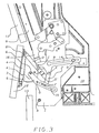
- Fig.3 is a view similar to the preceding one showing an intermediate phase of the door opening, at an angle of about 18°;
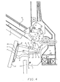
- Fig.4 is a view similar to the preceding one showing an advanced phase of the door opening, at an angle of about 55°; and
- Fig.5 is a view similar to the preceding one with the door fully open at about 90°.
-
- With reference to figs.1 and 2, there is seen that a domestic appliance according to the present invention is provided with a mounting and moving system of a
bottom panel 12 which clearly results arranged flush between thedecorative panel 11 ofdoor 9 and apanel 13 of the underlying piece of furniture (e.g. the front face of a drawer). - This system includes a
support 1, secured in the front portion of thebase 10 of the domestic appliance, on which are pivoted anupper rod 2 and a lower rod 3 (not visible in fig.1) of a parallelogram hinge, through respective pins B and A. The forward ends of theserods plate 4 which carries thebottom panel 12, and a return spring (not illustrated) is arranged between thelower rod 3 andbase 10. - On
support 1, through a relevant pin G, there is also pivoted alever 5 extending downward into a portion where aslot 15 is formed, as well as upward into a portion that carries at its distal end a low-friction push member, preferably aroller 16. -
Support 1 also carries ahorizontal rod 8 that is pivoted at the forward end through a pin C to abar 6 integral withdoor 9, while at the rear end it is guided by a pin D, secured to support 1, sliding within aslot 14. - The
horizontal rod 8 is also connected to theupper rod 2 through a connectingrod 7 pivoted between a pin E, located in the lower portion ofrod 8, and a pin F located at the bottom end of a bottom extension 2' ofrod 2 extending below pin B. Said pinF connecting rods slot 15 oflever 5. - In the closed door position illustrated in fig.1,
roller 16 abuts against the rear of thelower rod 3 close to the top pin A'. Moreover, in said position,bar 6 andlever 5 are substantially vertical and pin C is at the lowest point of his movement path, well below pin D. - The simple and effective operation of the present mounting and moving system for
panel 12 is readily understood from the description above with the help of figs.3-5. - At the beginning of the opening, door 9 (thanks to "variable fulcrum" hinges) performs a rototranslational movement that prevents at the beginning of the opening the interference between
panel 11 and the underlying panel 12 (fig.2). The door opening movement, throughbar 6 and pin C, causes the rising and rearward translation of thehorizontal rod 8 on the fixed pin D, while determining a counter-clockwise rotation of thepush lever 5 around pin G, due to the sliding of pin F withinslot 15, and a traction on the connectingrod 7 through pin E. This results in a push ofroller 16 on thelower rod 3 to help the initial movement ofpanel 12, said push being limited to the first 5°-10° of the opening. - The traction on
rod 7 causes in turn, through pin F, a counter-clockwise rotation of theupper rod 2, which together with the push oflever 5 produces a forward movement ofpanel 12. In thisway panel 12 performs a rototranslational movement along the path allowed byrods rod 2 is directly driven byrod 7,rod 3 is "pulled" by the movement ofpanel 12. - This calculated movement of
panel 12 allows the advancing and rearward inclination thereof without interference either with theoverlying panel 11 or theunderlying panel 13. - When the complete opening of
door 9 is reached (fig.5),rods position bringing panel 12 to an advanced and lowered position in which there is no interference withpanel 11. It should also be noted that thelower rod 3 is shaped so as to avoid interference with theunderlying panel 13, since the straight connection line between pins A, A' is lower than the top edge of said panel. - Furthermore, in said position, pin F abuts against the bottom end of
slot 15, acting as an end stop, and pin C is at the highest point of his movement path, just above pin D. - In the reverse closing movement, in order to facilitate the raising of
panel 12 provided by the push ofrod 8 onrod 2, throughrod 7 and extension 2', also the return spring (not shown) arranged between thelower rod 3 andbase 10 cooperates. - From the above figures it is clear that in no phase of the movement the
top panel 11 or thebottom panel 12 move closer to the dishwasher or mutually interfere, or interfere with theunderlying panel 13, whereby there is no problem of interference with the furniture sides. Furthermore, since the whole mounting system is secured to the dishwasher, the latter can be easily pulled out of the furniture for maintenance, if any, without requiring the removal of any member of the furniture. - It is clear that the above-described and illustrated embodiment of the domestic appliance according to the invention is just an example susceptible of various modifications. In particular, the exact shape and arrangement of the levers and pins can be somewhat changed according to specific needs, as long as the above-described type of movement of
panel 12 is retained.
Claims (5)
- A built-in domestic appliance with a door (9) hinged along its bottom side, provided with a top front decorative panel (11) applied to said door and with a bottom front decorative panel (12) arranged flush with said top front decorative panel (11), said bottom panel (12) being applied to the appliance through a mounting system including a plate (4) to which an upper rod (2) and a lower rod (3) are pivotally connected (A', B'), the other ends of said rods (2, 3) being pivotally connected (A, B) to a support (1) secured to the base (10) of the appliance, characterized in that the mounting system further comprises:a) a horizontal rod (8) comprising a forward end pivotally connected (C) to a bar (6) integral with the door and vertically oriented when the door is closed, and a rearward end guided by a guiding member (D) secured to the appliance;b) a push lever (5), pivotally connected (G) to said support (1), comprising a downwardly directed portion in which a slot (15) is formed, as well as an upwardly directed portion carrying at its distal end a low-friction push member, which abuts against the rear of the lower rod (3) when the door is closed; andc) a connecting rod (7) pivotally connected (E, F) to a lower portion of the horizontal rod (8) and to a bottom extension (2') of said upper rod (2), said slot (15) slidingly receiving the pin (F) that connects the connecting rod (7) to the upper rod (2).
- A built-in domestic appliance according to claim 1, characterized in that the low-friction push member arranged at the end of the push lever (5) is a roller (16).
- A built-in domestic appliance according to claim 1 or 2, characterized in that the door opening movement causes the rising and rear ward translation of the horizontal rod (8) that is guided by a pin (D) secured to the support (1) and engaged in a slot (14).
- A built-in domestic appliance according to one of the preceding claims, characterized in that it further includes a return spring arranged between the lower rod (3) and the base (10).
- A built-in domestic appliance according to one of the preceding claims, characterized in that the lower rod (3) is shaped to pass higher that the connection line between the pins (A, A') connecting it to the plate (4) and the support (1).
Priority Applications (5)
| Application Number | Priority Date | Filing Date | Title |
|---|---|---|---|
| DE602004000223T DE602004000223T2 (en) | 2004-03-01 | 2004-03-01 | Built-in home appliance with decorative front panel |
| EP04425132A EP1591040B1 (en) | 2004-03-01 | 2004-03-01 | Built-in domestic appliance with front decorative panels |
| ES04425132T ES2253729T3 (en) | 2004-03-01 | 2004-03-01 | INTEGRATED HOME APPLIANCE WITH DECORATIVE FRONT PANELS. |
| AT04425132T ATE311791T1 (en) | 2004-03-01 | 2004-03-01 | BUILT-IN HOUSEHOLD APPLIANCE WITH DECORATIVE FRONT PANEL |
| PL04425132T PL1591040T3 (en) | 2004-03-01 | 2004-03-01 | Built-in domestic appliance with front decorative panels |
Applications Claiming Priority (1)
| Application Number | Priority Date | Filing Date | Title |
|---|---|---|---|
| EP04425132A EP1591040B1 (en) | 2004-03-01 | 2004-03-01 | Built-in domestic appliance with front decorative panels |
Publications (2)
| Publication Number | Publication Date |
|---|---|
| EP1591040A1 EP1591040A1 (en) | 2005-11-02 |
| EP1591040B1 true EP1591040B1 (en) | 2005-12-07 |
Family
ID=34932435
Family Applications (1)
| Application Number | Title | Priority Date | Filing Date |
|---|---|---|---|
| EP04425132A Expired - Lifetime EP1591040B1 (en) | 2004-03-01 | 2004-03-01 | Built-in domestic appliance with front decorative panels |
Country Status (5)
| Country | Link |
|---|---|
| EP (1) | EP1591040B1 (en) |
| AT (1) | ATE311791T1 (en) |
| DE (1) | DE602004000223T2 (en) |
| ES (1) | ES2253729T3 (en) |
| PL (1) | PL1591040T3 (en) |
Families Citing this family (3)
| Publication number | Priority date | Publication date | Assignee | Title |
|---|---|---|---|---|
| US9387912B2 (en) | 2009-10-09 | 2016-07-12 | Driessen Aircraft Interior Systems, Inc. | Panel inserts for aircraft and other vessels |
| WO2011044476A2 (en) | 2009-10-09 | 2011-04-14 | Mag Aerospace Industries, Inc. | Panel inserts for aircraft and other vessels |
| DE102020107150A1 (en) * | 2020-03-16 | 2021-09-16 | Miele & Cie. Kg | Home appliance |
Family Cites Families (4)
| Publication number | Priority date | Publication date | Assignee | Title |
|---|---|---|---|---|
| US4900109A (en) * | 1989-04-04 | 1990-02-13 | General Electric Company | Versatile dishwasher front construction |
| DE10031688A1 (en) * | 2000-06-29 | 2002-01-17 | Bulthaup Gmbh & Co Kg Kuechens | Cover for furniture |
| DE10063353A1 (en) * | 2000-12-19 | 2002-06-20 | Bsh Bosch Siemens Hausgeraete | Door for domestic device has base panel that can be moved approximately vertically down into desired position from initial position by hinge between housing and panel |
| EP1380250A1 (en) * | 2002-07-08 | 2004-01-14 | Bonferraro S.p.A. | Built in domestic appliance with front decorative panels |
-
2004
- 2004-03-01 DE DE602004000223T patent/DE602004000223T2/en not_active Expired - Lifetime
- 2004-03-01 EP EP04425132A patent/EP1591040B1/en not_active Expired - Lifetime
- 2004-03-01 ES ES04425132T patent/ES2253729T3/en not_active Expired - Lifetime
- 2004-03-01 AT AT04425132T patent/ATE311791T1/en not_active IP Right Cessation
- 2004-03-01 PL PL04425132T patent/PL1591040T3/en unknown
Also Published As
| Publication number | Publication date |
|---|---|
| DE602004000223D1 (en) | 2006-01-12 |
| EP1591040A1 (en) | 2005-11-02 |
| DE602004000223T2 (en) | 2006-08-17 |
| ES2253729T3 (en) | 2006-06-01 |
| ATE311791T1 (en) | 2005-12-15 |
| PL1591040T3 (en) | 2006-03-31 |
Similar Documents
| Publication | Publication Date | Title |
|---|---|---|
| EP1894509B1 (en) | Built-in domestic appliance with decorative panel applied to the door | |
| EP1875850A1 (en) | Built-in domestic appliance with decorative panel applied to the door | |
| CN110582676B (en) | Cooking appliance with a cable pull for automatically pivoting the door | |
| EP1529482B1 (en) | Built-in domestic appliance with decorative panel applied to the door | |
| EP3108791B1 (en) | Electrical household appliance and hinge for an electrical household appliance | |
| EP2881029B1 (en) | Built-in domestic appliance with decorative panel applied to the door | |
| EP1502536B1 (en) | Built-in domestic appliance with front decorative panels | |
| WO2008038320A1 (en) | Dishwasher | |
| EP2482703A1 (en) | A built-in dishwasher comprising a decorative panel on its door | |
| EP1591040B1 (en) | Built-in domestic appliance with front decorative panels | |
| US11371715B2 (en) | Cooking appliance comprising a lowerable door, which has a specific retaining spring for a bearing bush | |
| US3779624A (en) | Cabinet having a kick plate assembly | |
| EP1702550B1 (en) | Panel moving system for a built-in appliance or the like, with anti-crushing functionality | |
| EP1364609B1 (en) | Built-in domestic appliance with decorative panel applied to the door | |
| EP1380250A1 (en) | Built in domestic appliance with front decorative panels | |
| KR102422099B1 (en) | Refrigerator | |
| GB2079589A (en) | A door for domestic electrical appliances | |
| US2302217A (en) | Door for broiler drawers | |
| GB2238576A (en) | Domestic dishwasher | |
| EP1329175B1 (en) | Cupboard built in arrangement for a dishwasher | |
| EP0744521A1 (en) | Hinge with movable axis of rotation in particular for the panel-finished doors of built-in dish washing machines | |
| EP1366703B1 (en) | Built-in domestic appliance with decorative panel applied to the door | |
| US9101257B2 (en) | Appliance with an inset base element | |
| EP2904955B1 (en) | Built-in domestic appliance with decorative panel applied to the door | |
| EP1374753B1 (en) | Built-in domestic appliance with decorative panel applied to the door |
Legal Events
| Date | Code | Title | Description |
|---|---|---|---|
| GRAP | Despatch of communication of intention to grant a patent |
Free format text: ORIGINAL CODE: EPIDOSNIGR1 |
|
| GRAS | Grant fee paid |
Free format text: ORIGINAL CODE: EPIDOSNIGR3 |
|
| PUAI | Public reference made under article 153(3) epc to a published international application that has entered the european phase |
Free format text: ORIGINAL CODE: 0009012 |
|
| GRAA | (expected) grant |
Free format text: ORIGINAL CODE: 0009210 |
|
| 17P | Request for examination filed |
Effective date: 20041004 |
|
| AK | Designated contracting states |
Kind code of ref document: A1 Designated state(s): AT BE BG CH CY CZ DE DK EE ES FI FR GB GR HU IE IT LI LU MC NL PL PT RO SE SI SK TR |
|
| AX | Request for extension of the european patent |
Extension state: AL LT LV MK |
|
| AK | Designated contracting states |
Kind code of ref document: B1 Designated state(s): AT BE BG CH CY CZ DE DK EE ES FI FR GB GR HU IE IT LI LU MC NL PL PT RO SE SI SK TR |
|
| AX | Request for extension of the european patent |
Extension state: AL LT LV MK |
|
| PG25 | Lapsed in a contracting state [announced via postgrant information from national office to epo] |
Ref country code: LI Free format text: LAPSE BECAUSE OF FAILURE TO SUBMIT A TRANSLATION OF THE DESCRIPTION OR TO PAY THE FEE WITHIN THE PRESCRIBED TIME-LIMIT Effective date: 20051207 Ref country code: FI Free format text: LAPSE BECAUSE OF FAILURE TO SUBMIT A TRANSLATION OF THE DESCRIPTION OR TO PAY THE FEE WITHIN THE PRESCRIBED TIME-LIMIT Effective date: 20051207 Ref country code: CZ Free format text: LAPSE BECAUSE OF FAILURE TO SUBMIT A TRANSLATION OF THE DESCRIPTION OR TO PAY THE FEE WITHIN THE PRESCRIBED TIME-LIMIT Effective date: 20051207 Ref country code: CH Free format text: LAPSE BECAUSE OF FAILURE TO SUBMIT A TRANSLATION OF THE DESCRIPTION OR TO PAY THE FEE WITHIN THE PRESCRIBED TIME-LIMIT Effective date: 20051207 Ref country code: AT Free format text: LAPSE BECAUSE OF FAILURE TO SUBMIT A TRANSLATION OF THE DESCRIPTION OR TO PAY THE FEE WITHIN THE PRESCRIBED TIME-LIMIT Effective date: 20051207 Ref country code: SI Free format text: LAPSE BECAUSE OF FAILURE TO SUBMIT A TRANSLATION OF THE DESCRIPTION OR TO PAY THE FEE WITHIN THE PRESCRIBED TIME-LIMIT Effective date: 20051207 Ref country code: NL Free format text: LAPSE BECAUSE OF FAILURE TO SUBMIT A TRANSLATION OF THE DESCRIPTION OR TO PAY THE FEE WITHIN THE PRESCRIBED TIME-LIMIT Effective date: 20051207 Ref country code: SK Free format text: LAPSE BECAUSE OF FAILURE TO SUBMIT A TRANSLATION OF THE DESCRIPTION OR TO PAY THE FEE WITHIN THE PRESCRIBED TIME-LIMIT Effective date: 20051207 |
|
| REG | Reference to a national code |
Ref country code: GB Ref legal event code: FG4D |
|
| REG | Reference to a national code |
Ref country code: CH Ref legal event code: EP |
|
| REG | Reference to a national code |
Ref country code: IE Ref legal event code: FG4D |
|
| REF | Corresponds to: |
Ref document number: 602004000223 Country of ref document: DE Date of ref document: 20060112 Kind code of ref document: P |
|
| REG | Reference to a national code |
Ref country code: SE Ref legal event code: TRGR |
|
| PG25 | Lapsed in a contracting state [announced via postgrant information from national office to epo] |
Ref country code: IE Free format text: LAPSE BECAUSE OF NON-PAYMENT OF DUE FEES Effective date: 20060301 |
|
| PG25 | Lapsed in a contracting state [announced via postgrant information from national office to epo] |
Ref country code: GR Free format text: LAPSE BECAUSE OF FAILURE TO SUBMIT A TRANSLATION OF THE DESCRIPTION OR TO PAY THE FEE WITHIN THE PRESCRIBED TIME-LIMIT Effective date: 20060307 Ref country code: BG Free format text: LAPSE BECAUSE OF FAILURE TO SUBMIT A TRANSLATION OF THE DESCRIPTION OR TO PAY THE FEE WITHIN THE PRESCRIBED TIME-LIMIT Effective date: 20060307 Ref country code: DK Free format text: LAPSE BECAUSE OF FAILURE TO SUBMIT A TRANSLATION OF THE DESCRIPTION OR TO PAY THE FEE WITHIN THE PRESCRIBED TIME-LIMIT Effective date: 20060307 |
|
| PG25 | Lapsed in a contracting state [announced via postgrant information from national office to epo] |
Ref country code: MC Free format text: LAPSE BECAUSE OF NON-PAYMENT OF DUE FEES Effective date: 20060331 Ref country code: LU Free format text: LAPSE BECAUSE OF NON-PAYMENT OF DUE FEES Effective date: 20060331 |
|
| PG25 | Lapsed in a contracting state [announced via postgrant information from national office to epo] |
Ref country code: PT Free format text: LAPSE BECAUSE OF FAILURE TO SUBMIT A TRANSLATION OF THE DESCRIPTION OR TO PAY THE FEE WITHIN THE PRESCRIBED TIME-LIMIT Effective date: 20060508 |
|
| NLV1 | Nl: lapsed or annulled due to failure to fulfill the requirements of art. 29p and 29m of the patents act | ||
| REG | Reference to a national code |
Ref country code: ES Ref legal event code: FG2A Ref document number: 2253729 Country of ref document: ES Kind code of ref document: T3 |
|
| PG25 | Lapsed in a contracting state [announced via postgrant information from national office to epo] |
Ref country code: HU Free format text: LAPSE BECAUSE OF FAILURE TO SUBMIT A TRANSLATION OF THE DESCRIPTION OR TO PAY THE FEE WITHIN THE PRESCRIBED TIME-LIMIT Effective date: 20060608 |
|
| REG | Reference to a national code |
Ref country code: CH Ref legal event code: PL |
|
| AKX | Designation fees paid |
Designated state(s): AT BE BG CH CY CZ DE DK EE ES FI FR GB GR HU IE IT LI LU MC NL PL PT RO SE SI SK TR |
|
| ET | Fr: translation filed | ||
| PLBE | No opposition filed within time limit |
Free format text: ORIGINAL CODE: 0009261 |
|
| STAA | Information on the status of an ep patent application or granted ep patent |
Free format text: STATUS: NO OPPOSITION FILED WITHIN TIME LIMIT |
|
| 26N | No opposition filed |
Effective date: 20060908 |
|
| REG | Reference to a national code |
Ref country code: IE Ref legal event code: MM4A |
|
| PG25 | Lapsed in a contracting state [announced via postgrant information from national office to epo] |
Ref country code: EE Free format text: LAPSE BECAUSE OF FAILURE TO SUBMIT A TRANSLATION OF THE DESCRIPTION OR TO PAY THE FEE WITHIN THE PRESCRIBED TIME-LIMIT Effective date: 20051207 |
|
| PG25 | Lapsed in a contracting state [announced via postgrant information from national office to epo] |
Ref country code: TR Free format text: LAPSE BECAUSE OF FAILURE TO SUBMIT A TRANSLATION OF THE DESCRIPTION OR TO PAY THE FEE WITHIN THE PRESCRIBED TIME-LIMIT Effective date: 20051207 |
|
| PG25 | Lapsed in a contracting state [announced via postgrant information from national office to epo] |
Ref country code: RO Free format text: LAPSE BECAUSE OF FAILURE TO SUBMIT A TRANSLATION OF THE DESCRIPTION OR TO PAY THE FEE WITHIN THE PRESCRIBED TIME-LIMIT Effective date: 20051207 |
|
| PG25 | Lapsed in a contracting state [announced via postgrant information from national office to epo] |
Ref country code: CY Free format text: LAPSE BECAUSE OF FAILURE TO SUBMIT A TRANSLATION OF THE DESCRIPTION OR TO PAY THE FEE WITHIN THE PRESCRIBED TIME-LIMIT Effective date: 20051207 |
|
| PGFP | Annual fee paid to national office [announced via postgrant information from national office to epo] |
Ref country code: ES Payment date: 20100324 Year of fee payment: 7 |
|
| PGFP | Annual fee paid to national office [announced via postgrant information from national office to epo] |
Ref country code: PL Payment date: 20100225 Year of fee payment: 7 |
|
| PGFP | Annual fee paid to national office [announced via postgrant information from national office to epo] |
Ref country code: SE Payment date: 20100312 Year of fee payment: 7 |
|
| REG | Reference to a national code |
Ref country code: SE Ref legal event code: EUG |
|
| REG | Reference to a national code |
Ref country code: ES Ref legal event code: FD2A Effective date: 20120510 |
|
| PG25 | Lapsed in a contracting state [announced via postgrant information from national office to epo] |
Ref country code: ES Free format text: LAPSE BECAUSE OF NON-PAYMENT OF DUE FEES Effective date: 20110302 |
|
| REG | Reference to a national code |
Ref country code: PL Ref legal event code: LAPE |
|
| PG25 | Lapsed in a contracting state [announced via postgrant information from national office to epo] |
Ref country code: PL Free format text: LAPSE BECAUSE OF NON-PAYMENT OF DUE FEES Effective date: 20110301 |
|
| PG25 | Lapsed in a contracting state [announced via postgrant information from national office to epo] |
Ref country code: SE Free format text: LAPSE BECAUSE OF NON-PAYMENT OF DUE FEES Effective date: 20110302 |
|
| PGFP | Annual fee paid to national office [announced via postgrant information from national office to epo] |
Ref country code: FR Payment date: 20130408 Year of fee payment: 10 Ref country code: GB Payment date: 20130321 Year of fee payment: 10 |
|
| PGFP | Annual fee paid to national office [announced via postgrant information from national office to epo] |
Ref country code: BE Payment date: 20130320 Year of fee payment: 10 |
|
| GBPC | Gb: european patent ceased through non-payment of renewal fee |
Effective date: 20140301 |
|
| REG | Reference to a national code |
Ref country code: FR Ref legal event code: ST Effective date: 20141128 |
|
| PG25 | Lapsed in a contracting state [announced via postgrant information from national office to epo] |
Ref country code: GB Free format text: LAPSE BECAUSE OF NON-PAYMENT OF DUE FEES Effective date: 20140301 Ref country code: FR Free format text: LAPSE BECAUSE OF NON-PAYMENT OF DUE FEES Effective date: 20140331 |
|
| PG25 | Lapsed in a contracting state [announced via postgrant information from national office to epo] |
Ref country code: BE Free format text: LAPSE BECAUSE OF NON-PAYMENT OF DUE FEES Effective date: 20140331 |
|
| PGFP | Annual fee paid to national office [announced via postgrant information from national office to epo] |
Ref country code: DE Payment date: 20200320 Year of fee payment: 17 Ref country code: IT Payment date: 20200310 Year of fee payment: 17 |
|
| REG | Reference to a national code |
Ref country code: DE Ref legal event code: R119 Ref document number: 602004000223 Country of ref document: DE |
|
| PG25 | Lapsed in a contracting state [announced via postgrant information from national office to epo] |
Ref country code: DE Free format text: LAPSE BECAUSE OF NON-PAYMENT OF DUE FEES Effective date: 20211001 |
|
| PG25 | Lapsed in a contracting state [announced via postgrant information from national office to epo] |
Ref country code: IT Free format text: LAPSE BECAUSE OF NON-PAYMENT OF DUE FEES Effective date: 20210301 |