EP1590851B9 - Dispositif de pilotage d'entrainement de films dans un dispositif de realisation d'ensembles multicouches - Google Patents
Dispositif de pilotage d'entrainement de films dans un dispositif de realisation d'ensembles multicouches Download PDFInfo
- Publication number
- EP1590851B9 EP1590851B9 EP03799658A EP03799658A EP1590851B9 EP 1590851 B9 EP1590851 B9 EP 1590851B9 EP 03799658 A EP03799658 A EP 03799658A EP 03799658 A EP03799658 A EP 03799658A EP 1590851 B9 EP1590851 B9 EP 1590851B9
- Authority
- EP
- European Patent Office
- Prior art keywords
- drive means
- fact
- winding
- mandrel
- rollers
- Prior art date
- Legal status (The legal status is an assumption and is not a legal conclusion. Google has not performed a legal analysis and makes no representation as to the accuracy of the status listed.)
- Expired - Lifetime
Links
- 230000000712 assembly Effects 0.000 title claims abstract description 19
- 238000000429 assembly Methods 0.000 title claims abstract description 19
- 238000004804 winding Methods 0.000 claims abstract description 115
- 238000011144 upstream manufacturing Methods 0.000 claims description 30
- 238000006073 displacement reaction Methods 0.000 claims description 16
- 238000012937 correction Methods 0.000 claims description 15
- 238000004146 energy storage Methods 0.000 claims description 10
- 238000000034 method Methods 0.000 claims description 6
- 238000004519 manufacturing process Methods 0.000 claims description 2
- 238000003860 storage Methods 0.000 abstract description 2
- 239000010410 layer Substances 0.000 description 50
- 230000006870 function Effects 0.000 description 31
- 239000003792 electrolyte Substances 0.000 description 28
- 230000000536 complexating effect Effects 0.000 description 26
- 238000005520 cutting process Methods 0.000 description 18
- 238000010438 heat treatment Methods 0.000 description 15
- KWGRBVOPPLSCSI-WPRPVWTQSA-N (-)-ephedrine Chemical compound CN[C@@H](C)[C@H](O)C1=CC=CC=C1 KWGRBVOPPLSCSI-WPRPVWTQSA-N 0.000 description 13
- WHXSMMKQMYFTQS-UHFFFAOYSA-N Lithium Chemical compound [Li] WHXSMMKQMYFTQS-UHFFFAOYSA-N 0.000 description 13
- 229910052744 lithium Inorganic materials 0.000 description 13
- 238000001514 detection method Methods 0.000 description 8
- 238000003825 pressing Methods 0.000 description 7
- 230000001681 protective effect Effects 0.000 description 7
- 238000007664 blowing Methods 0.000 description 5
- 230000001276 controlling effect Effects 0.000 description 5
- 230000007547 defect Effects 0.000 description 5
- 238000010030 laminating Methods 0.000 description 5
- 230000000670 limiting effect Effects 0.000 description 4
- -1 polyoxyethylene Polymers 0.000 description 4
- 239000002356 single layer Substances 0.000 description 4
- 229920003171 Poly (ethylene oxide) Polymers 0.000 description 3
- 229920000297 Rayon Polymers 0.000 description 3
- 238000003475 lamination Methods 0.000 description 3
- 230000004807 localization Effects 0.000 description 3
- 230000036961 partial effect Effects 0.000 description 3
- 239000002964 rayon Substances 0.000 description 3
- 238000013519 translation Methods 0.000 description 3
- 230000014616 translation Effects 0.000 description 3
- 239000004698 Polyethylene Substances 0.000 description 2
- 239000004743 Polypropylene Substances 0.000 description 2
- 241001080024 Telles Species 0.000 description 2
- 230000001133 acceleration Effects 0.000 description 2
- 239000003990 capacitor Substances 0.000 description 2
- 230000008859 change Effects 0.000 description 2
- 238000013016 damping Methods 0.000 description 2
- 238000011143 downstream manufacturing Methods 0.000 description 2
- 230000000694 effects Effects 0.000 description 2
- 239000012467 final product Substances 0.000 description 2
- 238000011065 in-situ storage Methods 0.000 description 2
- 238000003780 insertion Methods 0.000 description 2
- 230000037431 insertion Effects 0.000 description 2
- 239000000463 material Substances 0.000 description 2
- 238000005192 partition Methods 0.000 description 2
- 229920000139 polyethylene terephthalate Polymers 0.000 description 2
- 239000005020 polyethylene terephthalate Substances 0.000 description 2
- 230000008569 process Effects 0.000 description 2
- 239000000047 product Substances 0.000 description 2
- 230000001360 synchronised effect Effects 0.000 description 2
- OKTJSMMVPCPJKN-UHFFFAOYSA-N Carbon Chemical compound [C] OKTJSMMVPCPJKN-UHFFFAOYSA-N 0.000 description 1
- 238000009825 accumulation Methods 0.000 description 1
- 238000004026 adhesive bonding Methods 0.000 description 1
- 230000032683 aging Effects 0.000 description 1
- XAGFODPZIPBFFR-UHFFFAOYSA-N aluminium Chemical compound [Al] XAGFODPZIPBFFR-UHFFFAOYSA-N 0.000 description 1
- 229910052782 aluminium Inorganic materials 0.000 description 1
- 238000013459 approach Methods 0.000 description 1
- 230000004888 barrier function Effects 0.000 description 1
- 230000033228 biological regulation Effects 0.000 description 1
- 230000015572 biosynthetic process Effects 0.000 description 1
- 230000000903 blocking effect Effects 0.000 description 1
- 239000011248 coating agent Substances 0.000 description 1
- 238000000576 coating method Methods 0.000 description 1
- 230000000295 complement effect Effects 0.000 description 1
- 125000004122 cyclic group Chemical group 0.000 description 1
- 238000011161 development Methods 0.000 description 1
- 230000018109 developmental process Effects 0.000 description 1
- 238000010586 diagram Methods 0.000 description 1
- 238000009792 diffusion process Methods 0.000 description 1
- 238000000605 extraction Methods 0.000 description 1
- 239000007888 film coating Substances 0.000 description 1
- 238000009501 film coating Methods 0.000 description 1
- 238000007667 floating Methods 0.000 description 1
- 239000003292 glue Substances 0.000 description 1
- 229910002804 graphite Inorganic materials 0.000 description 1
- 239000010439 graphite Substances 0.000 description 1
- 230000001939 inductive effect Effects 0.000 description 1
- 238000009434 installation Methods 0.000 description 1
- 239000002346 layers by function Substances 0.000 description 1
- 229910003002 lithium salt Inorganic materials 0.000 description 1
- 159000000002 lithium salts Chemical class 0.000 description 1
- 238000012423 maintenance Methods 0.000 description 1
- 230000007246 mechanism Effects 0.000 description 1
- 230000015654 memory Effects 0.000 description 1
- 238000003032 molecular docking Methods 0.000 description 1
- 150000004767 nitrides Chemical class 0.000 description 1
- 230000003287 optical effect Effects 0.000 description 1
- 230000010355 oscillation Effects 0.000 description 1
- 230000003071 parasitic effect Effects 0.000 description 1
- 239000002245 particle Substances 0.000 description 1
- 238000007747 plating Methods 0.000 description 1
- 229920000573 polyethylene Polymers 0.000 description 1
- 229920001155 polypropylene Polymers 0.000 description 1
- 238000012545 processing Methods 0.000 description 1
- 230000000750 progressive effect Effects 0.000 description 1
- 238000011084 recovery Methods 0.000 description 1
- 230000009467 reduction Effects 0.000 description 1
- 230000001105 regulatory effect Effects 0.000 description 1
- 238000005070 sampling Methods 0.000 description 1
- 238000012216 screening Methods 0.000 description 1
- 238000007789 sealing Methods 0.000 description 1
- 238000000926 separation method Methods 0.000 description 1
- 238000010008 shearing Methods 0.000 description 1
- 239000002904 solvent Substances 0.000 description 1
- 230000003068 static effect Effects 0.000 description 1
- 230000035882 stress Effects 0.000 description 1
- 239000000126 substance Substances 0.000 description 1
- 238000012549 training Methods 0.000 description 1
- 230000007306 turnover Effects 0.000 description 1
- 238000002604 ultrasonography Methods 0.000 description 1
- 230000003313 weakening effect Effects 0.000 description 1
Images


Classifications
-
- H—ELECTRICITY
- H01—ELECTRIC ELEMENTS
- H01G—CAPACITORS; CAPACITORS, RECTIFIERS, DETECTORS, SWITCHING DEVICES, LIGHT-SENSITIVE OR TEMPERATURE-SENSITIVE DEVICES OF THE ELECTROLYTIC TYPE
- H01G13/00—Apparatus specially adapted for manufacturing capacitors; Processes specially adapted for manufacturing capacitors not provided for in groups H01G4/00 - H01G11/00
- H01G13/02—Machines for winding capacitors
-
- H—ELECTRICITY
- H01—ELECTRIC ELEMENTS
- H01M—PROCESSES OR MEANS, e.g. BATTERIES, FOR THE DIRECT CONVERSION OF CHEMICAL ENERGY INTO ELECTRICAL ENERGY
- H01M10/00—Secondary cells; Manufacture thereof
- H01M10/06—Lead-acid accumulators
- H01M10/12—Construction or manufacture
- H01M10/14—Assembling a group of electrodes or separators
-
- B—PERFORMING OPERATIONS; TRANSPORTING
- B65—CONVEYING; PACKING; STORING; HANDLING THIN OR FILAMENTARY MATERIAL
- B65H—HANDLING THIN OR FILAMENTARY MATERIAL, e.g. SHEETS, WEBS, CABLES
- B65H18/00—Winding webs
- B65H18/08—Web-winding mechanisms
- B65H18/10—Mechanisms in which power is applied to web-roll spindle
-
- B—PERFORMING OPERATIONS; TRANSPORTING
- B65—CONVEYING; PACKING; STORING; HANDLING THIN OR FILAMENTARY MATERIAL
- B65H—HANDLING THIN OR FILAMENTARY MATERIAL, e.g. SHEETS, WEBS, CABLES
- B65H39/00—Associating, collating, or gathering articles or webs
- B65H39/16—Associating two or more webs
-
- H—ELECTRICITY
- H01—ELECTRIC ELEMENTS
- H01G—CAPACITORS; CAPACITORS, RECTIFIERS, DETECTORS, SWITCHING DEVICES, LIGHT-SENSITIVE OR TEMPERATURE-SENSITIVE DEVICES OF THE ELECTROLYTIC TYPE
- H01G13/00—Apparatus specially adapted for manufacturing capacitors; Processes specially adapted for manufacturing capacitors not provided for in groups H01G4/00 - H01G11/00
-
- H—ELECTRICITY
- H01—ELECTRIC ELEMENTS
- H01M—PROCESSES OR MEANS, e.g. BATTERIES, FOR THE DIRECT CONVERSION OF CHEMICAL ENERGY INTO ELECTRICAL ENERGY
- H01M10/00—Secondary cells; Manufacture thereof
- H01M10/04—Construction or manufacture in general
- H01M10/0404—Machines for assembling batteries
- H01M10/0409—Machines for assembling batteries for cells with wound electrodes
-
- H—ELECTRICITY
- H01—ELECTRIC ELEMENTS
- H01M—PROCESSES OR MEANS, e.g. BATTERIES, FOR THE DIRECT CONVERSION OF CHEMICAL ENERGY INTO ELECTRICAL ENERGY
- H01M10/00—Secondary cells; Manufacture thereof
- H01M10/04—Construction or manufacture in general
- H01M10/0431—Cells with wound or folded electrodes
-
- B—PERFORMING OPERATIONS; TRANSPORTING
- B65—CONVEYING; PACKING; STORING; HANDLING THIN OR FILAMENTARY MATERIAL
- B65H—HANDLING THIN OR FILAMENTARY MATERIAL, e.g. SHEETS, WEBS, CABLES
- B65H2301/00—Handling processes for sheets or webs
- B65H2301/40—Type of handling process
- B65H2301/41—Winding, unwinding
- B65H2301/414—Winding
- B65H2301/4143—Performing winding process
- B65H2301/41432—Performing winding process special features of winding process
- B65H2301/414326—Performing winding process special features of winding process winding on core with non-circular cross-sectional profile, e.g. polygonal, oval, flat or slightly curved
-
- B—PERFORMING OPERATIONS; TRANSPORTING
- B65—CONVEYING; PACKING; STORING; HANDLING THIN OR FILAMENTARY MATERIAL
- B65H—HANDLING THIN OR FILAMENTARY MATERIAL, e.g. SHEETS, WEBS, CABLES
- B65H2301/00—Handling processes for sheets or webs
- B65H2301/40—Type of handling process
- B65H2301/41—Winding, unwinding
- B65H2301/414—Winding
- B65H2301/4148—Winding slitting
-
- Y—GENERAL TAGGING OF NEW TECHNOLOGICAL DEVELOPMENTS; GENERAL TAGGING OF CROSS-SECTIONAL TECHNOLOGIES SPANNING OVER SEVERAL SECTIONS OF THE IPC; TECHNICAL SUBJECTS COVERED BY FORMER USPC CROSS-REFERENCE ART COLLECTIONS [XRACs] AND DIGESTS
- Y02—TECHNOLOGIES OR APPLICATIONS FOR MITIGATION OR ADAPTATION AGAINST CLIMATE CHANGE
- Y02E—REDUCTION OF GREENHOUSE GAS [GHG] EMISSIONS, RELATED TO ENERGY GENERATION, TRANSMISSION OR DISTRIBUTION
- Y02E60/00—Enabling technologies; Technologies with a potential or indirect contribution to GHG emissions mitigation
- Y02E60/10—Energy storage using batteries
-
- Y—GENERAL TAGGING OF NEW TECHNOLOGICAL DEVELOPMENTS; GENERAL TAGGING OF CROSS-SECTIONAL TECHNOLOGIES SPANNING OVER SEVERAL SECTIONS OF THE IPC; TECHNICAL SUBJECTS COVERED BY FORMER USPC CROSS-REFERENCE ART COLLECTIONS [XRACs] AND DIGESTS
- Y02—TECHNOLOGIES OR APPLICATIONS FOR MITIGATION OR ADAPTATION AGAINST CLIMATE CHANGE
- Y02P—CLIMATE CHANGE MITIGATION TECHNOLOGIES IN THE PRODUCTION OR PROCESSING OF GOODS
- Y02P70/00—Climate change mitigation technologies in the production process for final industrial or consumer products
- Y02P70/50—Manufacturing or production processes characterised by the final manufactured product
Definitions
- the present invention relates to the field of electrical energy storage assemblies.
- the present invention relates in particular to multi-layer electrochemical assemblies based on polymeric materials comprising an electrolyte flanked by two electrodes respectively forming cathode and anode.
- the invention applies in particular, but not exclusively, to devices comprising a lithium-based anode.
- the present invention applies to the realization of capacitors, super-capacitors and generators or batteries.
- electrochemical assemblies can be found in the documents FR-A-2737339 , FR-A-2759087 , FR-A-2759211 , FR-A-2808622 .
- These sets are generally made from a plurality of single-layer or multi-layer films, collected and superimposed to form a complex.
- the complex thus obtained is generally wound on a circular mandrel of revolution.
- the known devices for producing electrical energy storage assemblies generally comprise a plurality of film feed coils, drive means for scrolling these films from the feed reels and means for superposing these films. in a complex.
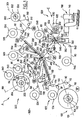
- the figure 34 schematically represents an example of a known system for controlling the running of a film strip.
- This system comprises a feed reel 1 from which the film is unwound, a detour roller 2, a dancer roll 3, a driving roller 4 and a mandrel 5 on which the film web is wound.
- the driving roller 4 drives the controlled-speed controlled-speed traveling belt on the basis of a pilot signal obtained at the output of the supply reel 1.
- the dancer roll 3 exerts on the web a force F to ensure a quasi-constant tensioning of the film strip.
- This system is particularly suitable for processes of continuous realization of windings on a circular mandrel of revolution, driven in rotation at a constant speed, for which stops and restarts are progressive.
- the inventors have found that it is particularly advantageous to make such electrical energy storage assemblies in the form of a generally planar multi-layer winding from the beginning, in order to avoid the occurrence of folds or equivalent defects in the structure of said sets.
- This mandrel can advantageously be driven at a non-constant speed so as to obtain an almost constant film scroll speed.
- the present invention nonetheless relates to a device for the realization, automatically, of electrical energy storage assemblies.
- the document GB 5,433,929 discloses a system for producing energy storage assemblies comprising a drum, means for driving a complex film, each consisting of a pair of rollers, and winding means for the complex film.
- the drum drives, by means of a gear mechanism, the winding means of the complex film as well as each pair of rollers,
- a particular object of the invention is therefore to propose a system for controlling the running of a complex film adapted to provide, at the request of a winding mandrel, in particular a mandrel having a non-circular cross section of revolution, a complex film rate at a speed corresponding to the linear speed of the mandrel.
- the present invention also relates to a method for producing such windings.
- upstream and downstream will be used with reference to the direction of movement of the complexes in the device, the term “upstream” qualifying the elements situated before a given reference, while the term “downstream” qualifies the elements located after this one.
- the supply means A have the function of conveying several single-layer or multi-layer assemblies 90, 92, 94, initially separated, and of complexing, that is to say superimposing and binding, these.
- the power supply means A also have the function of ensuring precise relative positioning of the longitudinal edges of the various layers involved in the final complex 96.
- the particular embodiment of the device illustrated on the figure 1 annexed is intended for the realization of generating sets formed of a stack of six layers: a collector 10 (for example of aluminum), a cathode 20 (for example based on POE (polyoxyethylene) and lithium salt), a an electrolyte layer 30, an anode 40, for example lithium, an electrolyte layer 50 and a cathode 60.
- the electrolytes 30 and 50 are for example based on LiV 3 O 8 or V 2 O 5 and POE.
- the Al collector 10 is preferably coated with an anticorrosion barrier, for example based on Ti nitride or the like, for example graphite.
- the supply means A comprises three separate feed magazines 100, 200 and 300.
- the feed means 100 is intended for supplying a four-layer complex 90 comprising the above-mentioned cathode 60 and electrolyte layer 50 sandwiched between two external protective films 80, 81 (see FIG. figure 9 ).
- the feed means 200 is for feeding the anode sheet 40 (see figure 11 ).
- the feed means 300 is for supplying a five-layer complex 92 comprising: the electrolyte 30, the cathode 20 and the collector 10 sandwiched between two outer protective films 82, 83 (see FIG. figure 13 ).
- each of these supply means 100, 200, 300 comprises a coil of the desired complex, 90, 40 or 92, previously made by any appropriate means, rotatably placed on the common frame 900 about respective axes of rotation. 102, 202, 302.
- the coils forming the feed magazines 100, 200 and 300 are removably mounted on the frame 900 to be replaced after exhaustion.
- the complexing of the three sets 90, 40 and 92 respectively from the three supply means 100, 200 and 300, that is to say the stacking of these sets, is performed in a complexing module C interposed between the output supply means 100, 200, 300, and the winding means E.
- the coils of the complexes 90, 40 and 92 placed in the three feed means 100, 200, 300 are respectively referenced 104, 204, 304.
- the four-layer complex 90 coming from the coil 104 is guided towards the complexing module C by rollers 110, 112, 114.
- the module 100 Downstream of the coil outlet 104, the module 100 includes a skin removal assembly 120 designed to remove the face-side film 81 to be complexed onto the electrolyte 50. depelliculation 120 is positioned between the return rollers 112 and 114.
- the three-layer complex structure 50, 60, 80 obtained at the outlet of the depelliculating assembly 120 is illustrated on the figure 10 .
- the supply means 100 comprises between the depelliculating assembly 120 and the complexing module C a heating module 130.
- the structure and function thereof will be described in more detail below.
- the module 300 Downstream of the coil outlet 304, the module 300 includes a dewatering assembly 320 designed to remove the face-on film 82 to be complexed on the electrolyte 30.
- This dewatering assembly 320 is positioned between the return rollers 312 and 314.
- the four-layer complex structure 83, 10, 20, 30 obtained at the outlet of the depelliculating assembly 320 is illustrated in FIG. figure 14 .
- the supply means 300 comprises between the depelliculating unit 320 and the complexing module C a heating module 330. The structure and function thereof will be described in more detail below.
- the feed assembly 200 for feeding an anode film, preferably lithium-based, comprises two feed rollers 240, 250 of respective films 84, 85.
- the films 84, 85 and the anode film 40 are guided by rollers 210, 212 towards a primary application assembly 260.
- the function of this assembly 260 is to combine in the form of an element comprising the anode layer. 40 sandwiched between the two films 84, 85, these initially separate films from the respective feed coils 204, 240 and 250.
- the element comprising the two films 84 and 85 surrounding the anode 40 is illustrated on the figure 12 .
- the applicator assembly 260 is preferably formed of two nip rollers 262, 264 rotatably mounted about respective parallel axes, receiving the three aforesaid films 84, 40, 85 between them.
- one 262 rollers has its axis of rotation fixed in space, while the second roller 264 placed opposite, which serves as a pressure roller, is urged to move against the roller 262 first cited, under a controlled effort, for example to the using elastic means, such as an elastic blade 263.
- At least one of the two rollers 262, 264 is motorized. It is controlled to alternately pull the element 84, 40, 85, and brake this element in synchronization with the downstream process. As such the rollers 262, 264 are slaved slave on the downstream process means.
- At least one of the rollers 262, 264 is mounted on a retractable crew, for example driven by a jack, to allow separation of the two rollers 262, 264 and thus facilitate the initial establishment of the element 84 , 40, 85 between them.
- the supply means 200 Downstream of the application assembly 260, the supply means 200 comprises a transverse sectioning module 270 of the anode layer 40.
- the sectioning module 270 comprises a hammer system 272 and anvil 274 respectively disposed on either side of the path of movement of the element 84, 40, 85.
- the hammer 272 operates by transverse linear striking through protective films 84, 85.
- At least one of the hammer 272 or the anvil 274, preferably the hammer 272, comprises a blunt edge.
- the hammer 272 is biased sequentially to the striking against the anvil 274 to define in the anode initial film 40, a downstream length corresponding to the desired winding. It will be noted that the hammer 272 operates on the element comprising the anode 40 taken in Sandwich between the two films 84, 85. However, the films 84, 85 are formed of a material capable of withstanding the striking of the hammer 272 to prevent any rupture of the films 84, 85.
- the two films 84, 85 are removed from the aforementioned element illustrated on the figure 12 at the outlet of the sectioning module 270 by means of depelliculating 220, 225. Where appropriate these depelliculating means 220, 225 may be formed by the hammer 272 and the anvil 274 themselves.
- the section of the anode 40 situated in front of the break line defined by the module 270 is driven by the downstream drive means, this anode section 40 being itself sandwiched between the two assemblies 50. , 60, 80, on the one hand, and 83, 10, 20, 30, on the other hand, in the complexing module C.
- the section of the anode film 40 located upstream of the rupture line is in turn driven by the films 84, 85, since these, as indicated previously, are not sectioned in the module 270.
- the set of films 80, 81, 82, 83, 84 and 85 has not only the function of avoiding pollution of the external faces of the complex by the external environment and of preventing the sticking of complex on the different rollers involved, but also participates in the training of their associated complex.
- the films 80, 81, 82, 83, 84 and 85 are advantageously based on PP (polypropylene), PE (polyethylene), PET (polyethylene terephthalate) or the like.
- the two film unwinders 240, 250 associated with the anode unwinder 204 are substantially adjacent and that the film 84 from the unwinder 240 surrounds the anode roll 204 on a winding arc ("docking" according to the expression dedicated) important (typically greater than 90 ° and preferably at least equal to 270 °) to both ensure good protection of this fragile film and ensure a mechanical drive adequate.
- This winding arc of the anode 204 by the film 84 is referenced ⁇ on the figure 7 attached. It varies according to the radius of the external turn of film present on the unwinder 240.
- the sequential control on the one hand, the driving of the films 84 and 85, and consequently of the anode section 40 located upstream of the rupture line, and on the other hand, the driving of the films 80 and 83 and therefore the anode section located downstream of this break line, is preferably adapted to define a gap, for example of the order of 20mm between the two aforementioned sections, after rupture. More precisely, the striking of the tool 272 is synchronized with the braking stop of the nip rollers 262, 264 so as to create a running interruption of the lithium 40 while the lamination continues downstream at the same speed.
- a scraper system 230 schematized on the figure 32 , arranged tangentially to the film concerned and having a polished edge 232 almost sharp, adapted to ensure peeling of the film through a sharp deviation thereof of at least 60 ° (see figure 32 ), if appropriate with turning on itself thereof substantially 180 °, according to a small radius of curvature (typically a radius close to 0.05mm).
- the scraper 230 is formed of a static blade blunt ridge 232 near the plane of displacement, upstream, of the film which wears the film.
- the edge 232 has its convexity directed downstream of the displacement of the film.
- the inventors have indeed determined that such a peel makes it possible to preserve the surface of the adjacent complex, whereas a tearing of the film without precaution generally deteriorates that -this.
- the aforementioned wiper 230 makes it possible to detach the film by shearing effect between the functional film and the protective film. By pulling the protective film around the edge 232 of the wiper 230, an elongation of the outer curvature of the protective film layer is created, which locally creates a tangential force on said layer, a micro-stretching of the film and a sliding effect of the film layer on the functional film, thus avoiding the tearing of particles of the functional product.
- the device also comprises means for adjusting the tensile force exerted on the protective film when it is deflected on the blunt edge 232 of the scraper 230.
- the scraper system of the depelliculating assemblies 120, 320 are referenced 122, 322.
- the films 81, 82, 84 and 85, removed on the stations 120, 320, 220 and 225, are directed towards respective rolls 124, 324, 224 and 229.
- the films 84 and 85 are guided by rollers 221, 222, on the one hand, and 226 on the other hand.
- the heating means 130 and 330 have the function of bringing to controlled temperature the external interface surface of the electrolytes 50 and 30 before they are brought into contact with the anode layer 40 in the complexing assembly C , to allow a good adhesion thereafter between the electrolyte layers 50 and 30 and the anode 40.
- these heating means 130 and 330 are formed by ovens with rapid temperature rise and rapid temperature reduction, capable of operating a hot air sweep, by forced circulating loop and regulated hot air, on the aforementioned interfaces.
- the heating means 130 and 330 are designed to dispense thermostatic compressed air, at the accuracy of ° C, for example at 60 ° C, on the electrolyte interfaces 50 and 30.
- the assembly of the device according to the present invention comprising sequential phases of interruption of displacement of the feed films upstream of the winding module E, to allow the cutting of the complex, the successive evacuation of each winding, and re-engagement of a next element, preferably ovens 130 and 330 are also controlled sequentially. That is to say that the diffusion of hot air, in the ovens 130 and 330 is interrupted cyclically when stopping the scrolling of the complexes, in order to avoid a harmful rise in temperature of the portion of the complexes located in these ovens. An overexposure to heat of these sections of films could indeed alter the quality of the final complex.
- the heating means 130, 330 may comprise means capable of sequentially blowing a jet of fresh compressed air onto the films . These means are typically adapted to reduce the temperature inside the furnaces to a value of the order of 40 ° C.
- ovens 130, 330 are formed of a loop circuit.
- heating elements consisting of bare electrically conductive multifilaments are placed opposite the output of the fans 134, 334.
- the anode 40 has a width less than the two films 84, 85, which may have identical widths and that the films 84, 85, overflow on both sides of the anode 40.
- the relative positioning of the film 83, the collector 10, the cathode 20 and the electrolyte 30 has a width less than the collector 10, a first edge of the cathode 20 is flush with a first edge of the collector 10, that the electrolyte 30 has a width greater than the cathode 20, that it overflows on either side thereof, that the electrolyte 30 overflows with respect to the first edge of the cathode 20 and of the collector 10, but that the second edge of the electrolyte 30 is set back from the collector 10, the film 83 has a first edge which protrudes with respect to the first edge of the electrolyte 30 but has a second edge which is flush with the second edge of the electrolyte 30.
- edges of the electrolytes 50 and 30 are superimposed, the anode 40 having a recessed edge of the electrolytes 50 and 30 on the emerging side of the collector 10, while the anode 40 passes electrolytes 30, 50 on the side opposite.
- the relative positioning of the layers represented on the Figures 17 and 18 is ensured during the realization of the supply coils 104 and 304.
- the relative positioning shown on the figure 19 is ensured during the filming in the module 260.
- the relative positioning represented on the figure 20 is ensured in the complexing module C.
- each of these feed means 100, 200 and 300 is mounted on an individual plate capable of controlled movement by relative to the general support frame 900 of the device. More precisely, preferably, each of these plates is pivotally mounted about a respective axis 101, 201, 301 and associated with a controlled displacement means.
- the means for detecting the positioning of the edges of the complexes are preferably formed by optical means, optionally infrared or laser, or ultrasonic means, arranged on a fork with two transmitter / receiver elements respectively arranged on either side the travel path of the multilayer.
- detection means 140 is placed between the roller 114 and the oven 130.
- the detection means 340 is placed between the roller 314 and the oven 330.
- the detection means 280 is placed between the primary lamination module 260 and the lamination module vs.
- the aforementioned displacement means may be formed of means based on pneumatic cylinders or any equivalent means.
- each of the aforementioned plates carries a damping means adapted to rest against the aforementioned common frame 900 to prevent vibration of the device.
- these damping means may be formed of suction cups.
- the aforementioned pivot axes 101, 201 and 301 are preferably parallel to the plate 900. They pass through the center (axis of rotation 102, 202, 302) of the unwinders 104, 204, 304 and by a median plane of the width of the reel placed on the unwinder. They are also parallel to the associated respective multilayer film sections located immediately upstream of the complexing complex C, imposed by the rollers 114, 262 and 314.
- the section of the anode film 40 situated upstream of the complexing module C, guided by the roller 262 is situated substantially along the bisector of the angle formed by the sections of the complexes 90 and 92 respectively unwinders 104 and 304, upstream of the complexing module, as guided by the rollers 114 and 314. More precisely still, upstream of the complexing module, the complexes 90 and 92 form an angle of about 150 ° between them and the anode film 40, located along their bisector is substantially 75 ° from each of these two complexes 90 and 92.
- the anode 40 is located, upstream of the complexing module C, substantially along the bisector of the sections of the films 84 and 85 located downstream of the depelliculeurs 220 and 225, which sections of films 84 and 85 are made between them. an angle of the order of 60 °.
- the return rollers 110, 112, 114, 221, 222, 226, 310, 312 and 314 make it possible to arrange the loaders 104, 204 and 304 in remote positions, and to bring the complex sections involved, upstream of the complexing module C so that the complete angle formed between them, at the level of the complexing module, is less than 180 °.
- the abovementioned relative positioning means of the base complexes not only have the function of guaranteeing a satisfactory electrical connection in the final product, and in particular a protection of the cathodes by overflow of the electrolyte, to avoid short circuits, but also to optimize the active surface in operation, in the smallest possible complex width.
- the receiving rollers of the different depelliculating assemblies 124, 224, 229, 324, 520 and 522 preferably comprise motorized reels.
- the unwinders 104, 204 and 304 are preferably motorized and parameterized to control the tensile force, constant on the multilayer films involved. It is indeed important to maintain constant traction on the films to have a reproducibility in the realization of the elements.
- the motors thus associated with the unwinders 104, 204 and 304 are alternately controlled as a motor, at the origin of a complex winding, and then as a brake when the drive of the complex is supported by downstream means.
- the motors of the various unwinders 104, 204, 304 and skin cleaners 124, 224, 229, 324, 520 and 522 are controlled by a central unit programmed to suitably change the motor forces and the respective braking forces required by taking into account the evolution of the diameter of rolled films and respectively the rolled film diameter.
- These diameters can be either calculated by the central unit, from the respective length of complex and treated film, or measured using appropriate sensors, for example ultrasound, respectively equipping each of the unwinders and reels concerned 104, 204, 304, 124, 224, 229, 324, 520 and 522.
- the complexing unit C preferably comprises two pinch rollers 400, 410, rotatably mounted about parallel axes and between which is conveyed the stack formed of the superimposed layers: film 80, cathode 60, electrolyte 50, anode 40, electrolyte 30, cathode 20, collector 10 and film 83.
- the two pinch rollers 400, 410 are biased in relative proximity under a controlled effort. They thus exert a controlled pressure force on the films conveyed between these rollers 400, 410.
- the axis of rotation of the roller 400 is fixed while the axis of rotation of the roller 410 is mounted on a roller.
- the roller 410 is also mounted on a retractable crew driven by a drive means, for example a cylinder, to ensure the release of the roller 410 on command and facilitate the establishment of the complex.
- the laminating rollers 400, 410 may be heating. Their diameter is typically at least 20 mm.
- the device further comprises, between the complexing module C and the winding module E, a set 500 with multiple functions and having in particular the function 1) of controlling the flow (length) of complex, in a module 510, 2) to perform localized longitudinal sections in the manifold 10, at a module 520, 3) to alternately ensure the drive of the complex at the beginning of a winding and the braking of this complex when it is placed in tension by the mandrel 610, at a module 530, 4) to remove the films 80 and 83, in a module 540, 5) to cut the layers 10 to 60 of the functional stack after scrolling.
- the detection device 510 is intended to control a correction of the synchronization defects that may result from micrograding of the complex on the rollers 400, 410, in order to ensure a constant feeding speed of the winder E.
- such a detection device 510 may be formed of a synchronization roller 512 mounted on a pivoting lever 514 and biased against the moving complex by a pneumatic cylinder or any equivalent means, and associated to an absolute encoder 516.
- the complex is pressed against the roller 512 by a roller 518 placed upstream on the path of displacement of the complex.
- the cutting module 520 is intended to perform a linear sequential slitting, in the longitudinal direction, on the edge of the collector 10.
- the resulting section sections are referenced 521.
- Each section 521 has a substantially equal length L1, while being slightly lower, at a half winding circumference on the mandrel 610.
- the actuation of this device 520 is controlled so that the slits 521 are found all superimposed on the same face of the final wound element.
- these slits 521 are operated with a pitch P1 identical to the length of each turn made on the mandrel 610. Insofar as this length is variable and increasing, because of the thickness accumulated on the mandrel 610, preferably the pitch of slits 521 is also variable.
- a transverse cutting segment 522 is operated between an axial end of the above-mentioned cut-out 521 and the adjacent free edge of the collector 10, and the external lateral strip 523 thus delimited in the collector 10 is extended to the outside of the wound element, to serve as a connector on the current concentrator.
- the collector band portion 10 thus deployed is referenced 525.
- the slitting device 520 is preferably of the "air-cut” type. It comprises an oscillating slitting blade 524 adapted to cut locally and sequentially the collector 10, between two rollers 526 and 528 serving to support the complex. On the figure 23 the pivoting movement of the blade 524 is shown schematically as 529.
- the drive module 530 preferably comprises two pinch rollers 532, 534, between which the complex assembly illustrated in FIGS. figures 15 and 20 . These two rollers 532, 534 are associated with respective engines. When routing the front end of the complex to the mandrel 610, the rollers 532, 534 are driven in drive motor mode. On the other hand, once the front end of the complex gripped by the mandrel 610, the latter becomes a motor, and the rollers 532, 534 are driven, by their respective motor, in the braking mode. This ensures a narrow veneer of the complex on the mandrel 610. These two nip rollers 532, 534 are located near the winding mandrel 610, upstream thereof.
- the drive of the nip rollers 400, 410 is slaved to that of the nip rollers 532, 534 which operate as master, with respect to the slave rollers 400, 410.
- At least one of the rollers 532, 534 is associated with a biasing means such that the rollers 532 and 534 exert on the complex that they frame, a controlled clamping force.
- At least one of the rollers 532, 534 is mounted on a retractable crew 535, for example driven by a jack 536, to facilitate the insertion of the complex between the rollers 532 and 534.
- the removal of the films 80 and 83 is carried out in the module 540 using scrapers 541, 543 similar to the scrapers 122 and 322 mentioned above.
- the films 80 and 83 are directed, after skinning, by means of rollers 542, 544 on accumulation rollers 546, 548. These are motorized, as indicated above.
- the complete transverse sectioning of the stack of the resulting 6 layers 10, 20, 30, 40, 50 and 60 of the complex is operated, just downstream of the depelliculating blades 541, 543, in the module 550, by any appropriate means.
- these cutting means 550 comprise a blade 552 comprising a cutting edge 554 formed of a convex dihedron with two symmetrical slopes (see FIG. figure 31 ) animated with a fast speed of displacement, under short run when the cut is required.
- the movements of the cutting blade 552 are controlled by a means 556 preferably formed of a jack. Furthermore, the cutting blade 552 is preferably placed on a retractable crew driven by a specific displacement means, for example a second jack 558, to allow the blade to be retracted on demand, in order to facilitate the installation of the blade. complex, or any other required maintenance intervention.
- a specific displacement means for example a second jack 558
- these cutting means may be formed of a hammer / anvil system similar to that previously described under references 272, 274.
- the cut made by the cutting means 552 is operated substantially in the middle of the gap formed in the lithium anode layer 40, at the striking station 572/574. So as we see on the figure 21 the anode layer 40 is set back from the other layers composing the winding, both at the front end and the rear end of the winding.
- the two axial ends Ei, Ee of the finished winding In are not superimposed.
- the outer end Ee of the winding is interrupted below the internal end Ei, to avoid an extra thickness at this level.
- the flattened finished winding generally has an identical thickness over its entire extent.
- the heating of the external faces of the stack is operated by any appropriate means in the module 560, for example by blowing hot air pulsed or passing on a heating roller.
- This heating is preferably provided by a retractable hot air blowing bar 562 located immediately downstream of the cutting device 550, for heating a transverse band of the complex, in order to prepare the heat-sealing of the end of the winding.
- the mandrel 610 has a cross section, transverse to its axis of rotation 611, non-circular of revolution.
- the mandrel 610 is substantially flat. It has a general section in a spindle. Typically the ratio between a major axis and a minor axis of its cross section is greater than 3, preferably greater than 5 and very advantageously greater than 10. It advantageously has a generally elliptical cross section.
- the outer casing of the mandrel 610 is preferably delimited by two sectors of convex revolution cylinder having identical radii (R1 on the figure 2 ), but distant parallel axes; moreover this outer envelope delimiting the cross section of the mandrel has blunt ends 615, 616 with a small radius.
- the mandrel 610 has a length (considered parallel to its axis of rotation 611) greater than the width of the complexes to be wound.
- the mandrel 610 is formed of two jaws 612, 614, symmetrical and complementary.
- the interface between the two jaws 612, 614, that is to say the mutual bearing surface between them, in the winding position, referenced 613 in the figures is preferably flat and connects the two curved surfaces convex outer shell of the mandrel away from the tapered ends of the outer shell ellipse.
- the major axis of the mandrel 610 is of the order of 12 cm while the small axis of the mandrel 610, formed by the two jaws 612 and 614 contiguous, is of the order of 9 to 10 mm
- the angle formed between the oblique plane which corresponds to the interface 613 between the two jaws 612, 614 and the major axis of the spindle is typically of the order of 2 , 5 °
- the spindle is terminated, on the ends 615, 616 of the major axis, by circular arcs of the order of 0.15 mm radius, and the distance separating the centers of the cylindrical main surfaces of the mandrel is greater than 6 times their radius R1.
- the two jaws 612, 614 are associated with drive means, for example hydraulic jacks or the like adapted to provide controlled controlled relative movement of the two jaws between a first position in which the two jaws 612, 614 are spaced apart. to allow the insertion of the front end of a complex stack 10 to 60 to be wound and a second position in which the two jaws 612, 614 are joined to allow the winding of the aforementioned complex stack.
- drive means for example hydraulic jacks or the like adapted to provide controlled controlled relative movement of the two jaws between a first position in which the two jaws 612, 614 are spaced apart. to allow the insertion of the front end of a complex stack 10 to 60 to be wound and a second position in which the two jaws 612, 614 are joined to allow the winding of the aforementioned complex stack.
- the mandrel 610 formed by the cooperation of the two jaws 612, 614, is itself driven to rotate about its axis 611, at a non-constant speed, according to terms to be defined later.
- the mandrel 610 is associated with a pressure roller 620.
- the arm 624 is rotated about an axis 625 eccentric with respect to the axis 622, and at a speed twice that of the mandrel 610, so that the roll 620 rolls successively on each of the faces of the mandrel 610, more precisely on the complex stack 10 to 60 wound on it, in order to press it regularly and prevent any formation of folds in the stack.
- the arm 624 is preferably rotated mechanically by the rotation of the mandrel 610 with a multiplier ratio of 2.
- Chuck 610 and arm 624 rotate in the same direction of rotation.
- the displacement kinematics of the mandrel 610 and the roll 620 are schematized on the Figures 3 to 6 associated.
- the mandrel 610 and the arm 624 may be driven by a common belt 640 associated with a motor 642, by respective rollers 618,628 engaged with said common belt 640.
- the roller 628 associated with it has a drive ratio two times lower than the roller 618 associated with the mandrel 610, is typically a circumferential dimension two times smaller.
- the device preferably further comprises a roller 570, downstream of the cutting blade 552, facing the hot air blowing nozzle 562.
- This roll 570 serves as the ultimate guide to the formed complex, before winding on the mandrel 610.
- the generatrix of the roll 570 on which the complex is based is situated in a plane defined by the generatrix of the upstream roll 534 and the generatrix of the mandrel 610 corresponding to the minor axis thereof (which generator serves as a support for the complex when it is positioned with its major axis parallel to the aforementioned plane, as illustrated on the figure 5 ).
- the assembly formed by the combination of the mandrel 610, the arm 624 and the pressure roller 622 is mounted on a drawer 630 itself associated with drive means adapted to move the assembly in translation between a winding position such that illustrated on the figure 1 , closer to the module 500 and an evacuation position, remote from these means 500, once the desired stacking length wound on the mandrel 610, to facilitate removal of the winding obtained.
- the aforementioned drawer 630 can also be moved into a temporary additional initial position, close to the supply pinching rollers 532, 534, when these are driven in motor, to ensure the gripping of the front end of the complex at beginning of the winding. Once this seizure is made, preferably the drawer 630 is spaced from the nip rollers 532, 534 for the actual winding.
- the mandrel 610 is preferably driven in a complete rotational movement over 360 ° after rupture of the wound complex and complete winding of this complex and the roller pressing 620 is held in support on the winding during this additional rotation in order to complete the "gluing" of the last turn of the winding, thanks to the above-mentioned preheating by the means 560.
- this heating can be completed by a hot air blowing at the winding station E.
- the device may further comprise, as illustrated in FIG. figure 8 , an additional retractable pressing roller 580, placed between the roller 570 and the mandrel 610.
- a roll 580 has the function of allowing the blocking of the complex during cutting and the plating of the end of the strip, on the mandrel 610.
- the roller 580 is preferably connected, by an elastic blade 582, to an oscillating assembly 584, driven by a jack 586.
- the roller 580 is placed in the position illustrated on FIG. figure 8 , spaced apart from the path of displacement of the complex and remote from the mandrel 610.
- the aforementioned oscillating equipment and the associated roller 580 are moved so that the roller 580 is plated on the face of the mandrel 610 opposite to that on which the roller 620 rests.
- This winding, obtained in a generally flattened form, thanks to the elliptical geometry of the mandrel 610 is then removed from the mandrel 610 and discharged by a robot or any equivalent means adapted to a pressing station 700 intended to perfect the flatness of each winding obtained .
- Such a robot may be formed of a pneumatic robot with clamping grippers for gripping the wound element for storing electrical energy on the mandrel 610, its extraction thereof and by various movements of rotations and translations, placing the element in the pressing station 700.
- this pressing station comprises a press, formed for example of a pressing cylinder 710, responsible for final flattening of the element. This operates preferably in masked time, while a next element is being wound up.
- the device may comprise means capable of ensuring during a limited sequence, at the end of the winding, a relative and reciprocating displacement in translation between the two jaws 612 and 614 constituting the mandrel 610. , in a direction parallel to the interface 613, to thereby vary the length of the major axis of the mandrel, in order to slightly "loosen” the winding relative to the mandrel 610, take off the first turn and peel the attachment of the first round .
- Each winding can then be directed to a magazine for performing subsequent steps required for connection under the desired serial / parallel configuration.
- a magazine for performing subsequent steps required for connection under the desired serial / parallel configuration.
- the mandrel 610 is rotated at a non-constant angular velocity controlled so that the linear speed of travel of the complex stack feeding the chuck 610 is constant.
- the invention makes it possible to guarantee a constant tensile force on the complex and consequently a perfect winding on mandrel 610, free of any fold or equivalent defect.
- the angular rotation speed of the mandrel 610 is corrected during the winding, to take account of the evolution of the winding radius resulting from the variation of complex thickness accumulated on the mandrel 610 in order to guarantee the linear speed constancy of scrolling.
- the pressure roller 620 comes into contact with, and remains in contact with, the complex film wound on the mandrel 610 when it is driven in rotation at low speed. This arrangement ensures a good contact between the pressure roller 620 and the wound film and therefore between the different layers of the wound film.
- the figure 28 which corresponds to the end of a winding has a range of speed evolution less extensive. Indeed, because of the complex thickness accumulated on the mandrel 610, the winding radius ratio covers a smaller range than at the origin of the winding.
- the speed of rotation varies at each turn over a period of 180 °.
- the winding time per revolution increases because the winding length on the mandrel 610 increases from one revolution to another due to the thickness added to the mandrel 610.
- the abscissa has an angle range of 0 to 180 °. This also covers the range from 180 to 360 °, the aforementioned curves having a periodicity of 180 °.
- the ordinate scales were used, the amplitude of the winding radius was recorded on the left, and the amplitude of the correction factor on the right.
- the inventors have in fact determined that the correction factor to be applied to the basic evolution V1 of the angular rotation speed taking into account only the evolution of the naked winding radius as a function of the angular position of the mandrel, to take into account of the thickness variation of the winding, could be likened to such a smoothed curve V2 which varies as a function of the angular position of the mandrel 610, while being fixed for a given angle regardless of the number of turns wound previously on the mandrel.
- the third column of the figure 30 represents the radius of the mandrel 610 bare, ie at the origin of the winding.
- the fourth column of the figure 30 represents the correction factor shown on the figure 29 .
- the pairs of columns that follow on the figure 30 represent two by two, for each winding tower, one the winding radius, and the other the speed of rotation of the mandrel 610.
- control of the driving motor of the mandrel 610 can be operated, either using precalculated data and stored in adapted memories, or using data calculated directly by a central unit on the base, on the one hand, the law of evolution of the winding radius as a function of the geometry of the mandrel 610 and, on the other hand, of the correction law depending on the evolution of this radius as a function of the thickness of the winding previously made on the mandrel.
- the aforementioned data are applied successively to each angular fraction of the rotation of the mandrel 610, on the drive motor thereof.
- the mandrel 610 reaches a speed of the order of 180 rpm, ie an angular speed of the order of 1090 ° / s, hence a sampling rate of the order of 1 ° / ms.
- the speed setpoint intended to be applied to the motor is selected of a digital nature, to avoid the processing of analog / digital converters.
- control module ensures the complete enslavement of all the means involved in the realization of the winding of the complex.
- the various aforementioned axes including the axes 102, 202, 302, rollers 104, 204, 304, the axis 611 of rotation of the mandrel 610, the axis of rotation of the pressure roller 620 and the pivot axis of the oscillating arm 624 , the axes of the rollers 124, 224, 240, 250, 229, 320, 520 and 522 associated with the films, the axes of the return rollers 110, 112, 114, 221, 222, 210, 212, 226, 310, 312, 314 and the axes of the pressure rollers 262, 264, 400, 410 are parallel to each other and preferably horizontal.
- the device comprises a housing divided into two compartments separated by a vertical partition 900: a first compartment, in a controlled dry atmosphere which houses all the means 100, 200, 300, 400, 500 , 600 and 700 above and a second compartment which houses the control means and drive / motor associated.
- the aforementioned vertical partition wall constitutes the support frame of the various axes of rotation described above.
- an additional sweep of dry air may be provided in the operational chamber.
- the present invention typically allows the realization of a complex winding comprising between 16 and 19 turns, corresponding to a complex length of the order of 4 to 5.5m, ie a total winding thickness of about 5 , 5 mm.
- the running speed of the complex is typically between 2 and 10 m / min. It is advantageously of the order of 6m / mm.
- the device according to the present invention is suitable for treating widths of complex of width between 50 and 150 mm.
- the present invention offers many advantages over the means proposed in the state of the art.
- rollers and rollers or unwinders used in the device of the invention have alternately motor and / or brake functions, depending on the sequence of the winding involved, to guarantee traction. constant on all films, complexes and associated films.
- the figure 33 represents a general synoptic of the main means of the device according to the present invention.
- the chuck 610, the pair of rollers 532, 534, the sensing and synchronizing roll 512, the pair of laminating rollers 400, 410, the feed reels 104, 204, 304 (on recalls that typically, but not exclusively, the roll 204 delivers a film of lithium while the rolls 104 and 304 respectively deliver complex three layers and two layers) and the pair of nip rollers 262 and 264.
- the mandrel 610 is the governing body of the entire winder. It receives its speed instruction from a control module 601.
- All scrolling parameters of the films making up the complex are set based on the request from the mandrel 610.
- the pair of motorized rollers 532, 534 is driven in driving mode causing a winding to route the leading edge on the mandrel 610.
- this pair of rollers 532, 534 is driven as a brake. It thus exerts on the complex film a constant and chosen traction, corresponding to a set point.
- the pair of rollers 532, 534 receives its brake torque setpoint from a control module 533.
- the pair of rollers 532, 534 is equipped with an incremental encoder 535, mounted on the drive geared motor, for assigning the master function to this pair of rollers.
- the pair of laminating rollers 400, 410 located upstream is also equipped with a coder 411. This pair of rollers 400, 410 is driven in Slave with respect to the aforementioned rollers 532 and 534. It operates as a motor.
- the encoder 535 associated with the pair of rollers 532, 534 measures the length of band that passes between said rollers 532 and 534.
- the corresponding length information is applied via a module 1010 to the pair of laminating rollers 400, 410 so that it routes, under the control of its own associated encoder 411, an identical length of tape.
- the synchronous oscillating roller 512 is positioned between the pairs of rollers 532, 534 and 400, 410. It is capable of a low deflection and is subjected to an adjustable force allowing ensure good contact with the band between the two aforementioned pairs of rollers 532, 534 and 400, 410.
- the encoder 513 of the roll 512 is positioned on the pivot axis of the roll 512. It is responsible for sensing the angular displacement of this roll 512.
- the encoder 513 is not solicited in the event of perfect synchronization between the two pairs of rollers 532, 534 and 400, 410. On the other hand, in the event of microglings or disturbances causing a desynchronization, the roll 512 is pivoted and the encoder 513 is sought.
- the encoder 513 is connected to the module 1010.
- the synchronization roller 512 provides, via the encoder 513, a correction, for example of +/- 10%, over the linear flow rate of the slave pair of rollers 400, 410.
- the range of +/- 10% of flow correction of the pair of laminating rollers 400, 410 is especially useful at launch, after loading new complex coils 104, 204 and 304 into the machine. Indeed, the operator who loads the coil engages the complexes without knowing or taking into account the initial position of the roller 512.
- the pair of slave rollers 400, 410 follows the movement of the pair of master rollers 532, 534, just as if these rollers were respectively located in pairs on the same mechanical shaft, having by their very nature at each of its ends the same positioning angular.
- the force F applied to the roller 512 is preferably generated by a pneumatic cylinder. This is powered by an electric signal / pressure converter whose pressure is proportional to the electrical signal from the setpoint.
- the setting of the setpoint makes it possible to adapt the force exerted to the complex involved.
- the force applied to the roller 512 can be obtained using any other suitable means, other than a pneumatic cylinder, for example a spring, a counterweight, a resilient member, an electromagnet, etc ...
- the pair of pinch rollers 262, 264 is itself a pair of slave motorized rollers of the motorized pinch rollers 400 and 410 located downstream. It is equipped with a 265 sensor.
- the function of the pair of rollers 262, 264 is to call the lithium strip originating from the unwinder 204 and intended to be complexed between the two two-layer and three-layer complexes coming from the unwinders 104 and 304.
- pair of rollers 532, 534 is the master with respect to the upstream pair of rollers 400, 410, which is itself the master with respect to the upstream pair of rollers 262, 264.
- the invention therefore uses at least two cascaded servocontrols.
- the pair of rollers 262, 264 is also driven from a setpoint related to the length information from the sensor 411 associated with the pair of rollers 400, 410, via a servo module 1012.
- a length setpoint applied to the pair of rollers 264, 262 slightly less than that applied to the torque 400, 410, in order to micro-stretch the lithium strip and remove its geometrical defects.
- downstream pair of rollers 262, 264 is driven by a setpoint of length equal to 99.5% of the linear speed of the torque 400, 410.
- the setpoint difference between the setpoint applied to the torque 262, 264 and the setpoint applied to the torque 400, 410 is advantageously parameterizable, in particular as a function of the deformations of the strip and its thickness.
- rollers 262, 264 are, inter alia, to stop the running of the lithium strip in a very short time, typically of the order of 1 ms, during the cutting operation of the lithium band at the fly.
- the sensors used in the context of the present invention can be the subject of many embodiments. They may be incremental encoders having a zero in the middle of the correction, or an analog displacement encoder (proportional inductive, variable resistance, depending on its length, magneto-resistive magnetic field sensor, ).
- the encoders 513 are of the absolute encoder type.
- each angular position at a non-volatile absolute position binary code makes it possible to locate the angular position of the roll 512, even after complete stoppage of the machine, without resetting the zero in the middle of the deflection.
- the length sensors are preferably adapted to measure increments of lengths between 1 mm and 4 ⁇ m, advantageously between 500 ⁇ m and 8 ⁇ m and very preferably between 100 and 40 ⁇ m.
- the length sensors are adapted to measure increments of lengths less than 1/1000 of the total length of the winding, advantageously less than 1/4000 of this length and very preferably less than 1/40 000 of this total length of the winding.
- Another way of controlling the slave torque 400, 410 with respect to the master torque 532, 534 is to replace the oscillating roller 512 with a fixed idler roller mounted on a strain gauge.
- the gauge is in this case sensitive to the band tension perceived by the idler roller.
- the torque 400, 410 remains slave with respect to the torque 532, 534.
- the torque 400, 410 is corrected in speed relative to the torque 532, 534 as a function of the tension of the tape read by the gauge of the idler roller so that the desired web tension is obtained.
- this variant does not have the same advantages as the servo-control in length previously described. It can indeed generate a speed oscillation around the set point and thus a variation of the band voltage.
- the device according to the invention may also comprise de-coating means comprising means for applying an air jet, preferably cold, to the region of divergence between the film and the assembly from which it is deflected.
- hot air furnaces may be replaced by heated rollers.
- the oscillating blade 524 can be controlled mechanically or electronically by the rotation of the mandrel 610 so that the successive steps of cuts made by this blade 524 are not strictly equal to each other along the length of a winding, but are This is a function of the angular position of the mandrel 610, which triggers the start and end of a cut. In this way, the cuts are found superimposed in the same sector of the wound element and at least approximately aligned radially.
Landscapes
- Engineering & Computer Science (AREA)
- Manufacturing & Machinery (AREA)
- Power Engineering (AREA)
- Chemical & Material Sciences (AREA)
- Chemical Kinetics & Catalysis (AREA)
- Electrochemistry (AREA)
- General Chemical & Material Sciences (AREA)
- Microelectronics & Electronic Packaging (AREA)
- Secondary Cells (AREA)
- Fixed Capacitors And Capacitor Manufacturing Machines (AREA)
- Cell Separators (AREA)
Applications Claiming Priority (3)
| Application Number | Priority Date | Filing Date | Title |
|---|---|---|---|
| US16511 | 1998-01-30 | ||
| FR0216511A FR2849286B1 (fr) | 2002-12-23 | 2002-12-23 | Dispositif de pilotage d'entrainement de films dans un dispositif de realisation d'ensembles multicouches |
| PCT/FR2003/003829 WO2004059779A1 (fr) | 2002-12-23 | 2003-12-19 | Dispositif de pilotage d’entrainement de films dans un dispositif de realisation d’ensembles multicouches |
Publications (3)
| Publication Number | Publication Date |
|---|---|
| EP1590851A1 EP1590851A1 (fr) | 2005-11-02 |
| EP1590851B1 EP1590851B1 (fr) | 2011-04-13 |
| EP1590851B9 true EP1590851B9 (fr) | 2011-09-28 |
Family
ID=35006171
Family Applications (1)
| Application Number | Title | Priority Date | Filing Date |
|---|---|---|---|
| EP03799658A Expired - Lifetime EP1590851B9 (fr) | 2002-12-23 | 2003-12-19 | Dispositif de pilotage d'entrainement de films dans un dispositif de realisation d'ensembles multicouches |
Country Status (7)
| Country | Link |
|---|---|
| EP (1) | EP1590851B9 (ko) |
| JP (1) | JP4762550B2 (ko) |
| KR (1) | KR101062139B1 (ko) |
| AU (1) | AU2003299375A1 (ko) |
| CA (1) | CA2511581C (ko) |
| FR (1) | FR2849286B1 (ko) |
| WO (1) | WO2004059779A1 (ko) |
Families Citing this family (3)
| Publication number | Priority date | Publication date | Assignee | Title |
|---|---|---|---|---|
| KR101889620B1 (ko) * | 2016-05-20 | 2018-08-21 | 주식회사 트리라인 | 중력을 이용하는 매트용 융착 금형 |
| WO2022130335A1 (en) * | 2020-12-18 | 2022-06-23 | Manz Italy S.R.L. | Winding method and apparatus |
| IT202100009251A1 (it) * | 2021-04-13 | 2022-10-13 | Manz Italy Srl | Metodo e apparato di avvolgimento |
Family Cites Families (5)
| Publication number | Priority date | Publication date | Assignee | Title |
|---|---|---|---|---|
| GB543929A (en) * | 1940-04-10 | 1942-03-19 | British Thomson Houston Co Ltd | Improvements in machines for winding electric condensers |
| JP2000068170A (ja) * | 1998-08-18 | 2000-03-03 | Matsushita Electric Ind Co Ltd | 帯状体の巻取装置 |
| JP2001118573A (ja) * | 1999-10-20 | 2001-04-27 | Toshiba Battery Co Ltd | シート状電極材料の加工装置 |
| JP3726623B2 (ja) * | 2000-02-29 | 2005-12-14 | 三菱電機株式会社 | 巻き取り装置および巻き取り方法 |
| JP2002270213A (ja) | 2001-03-14 | 2002-09-20 | Shimane Jidoki Kk | 扁平型電子部品用帯状素子の巻取方法及び巻取装置 |
-
2002
- 2002-12-23 FR FR0216511A patent/FR2849286B1/fr not_active Expired - Fee Related
-
2003
- 2003-12-19 EP EP03799658A patent/EP1590851B9/fr not_active Expired - Lifetime
- 2003-12-19 AU AU2003299375A patent/AU2003299375A1/en not_active Abandoned
- 2003-12-19 KR KR1020057011892A patent/KR101062139B1/ko active IP Right Grant
- 2003-12-19 CA CA2511581A patent/CA2511581C/fr not_active Expired - Fee Related
- 2003-12-19 WO PCT/FR2003/003829 patent/WO2004059779A1/fr active Application Filing
- 2003-12-19 JP JP2004563281A patent/JP4762550B2/ja not_active Expired - Fee Related
Also Published As
| Publication number | Publication date |
|---|---|
| WO2004059779A8 (fr) | 2005-10-06 |
| AU2003299375A8 (en) | 2004-07-22 |
| CA2511581A1 (fr) | 2004-07-15 |
| FR2849286B1 (fr) | 2005-02-18 |
| KR101062139B1 (ko) | 2011-09-05 |
| AU2003299375A1 (en) | 2004-07-22 |
| FR2849286A1 (fr) | 2004-06-25 |
| EP1590851A1 (fr) | 2005-11-02 |
| JP4762550B2 (ja) | 2011-08-31 |
| EP1590851B1 (fr) | 2011-04-13 |
| WO2004059779A1 (fr) | 2004-07-15 |
| CA2511581C (fr) | 2012-01-24 |
| KR20050089073A (ko) | 2005-09-07 |
| JP2006511911A (ja) | 2006-04-06 |
Similar Documents
| Publication | Publication Date | Title |
|---|---|---|
| EP1593173B1 (fr) | ARCHITECTURE DE DISPOSITIF DE BOBINAGE D’ENSEMBLE DE STOCKAGE D’ENERGIE-ELECTRIQUE | |
| EP1590851B1 (fr) | Dispositif de pilotage d'entrainement de films dans un dispositif de realisation d'ensembles multicouches | |
| EP1576630B1 (fr) | Dispositif de realisation d'ensemble de stockage d'energie electrique par enroulement sur mandrin plat | |
| EP1581978B1 (fr) | Collage de queue de feuille d'un element de batterie enroule lithum-polymere | |
| EP1581977B9 (fr) | Derouleur-aligneur pour machine a bobiner des films | |
| EP1656710B1 (fr) | Systeme d'interruption de lithium a la volee | |
| EP1590850B1 (fr) | Dispositif de coupe de fin d enroulement d un element de batterie enroule lithium-polymere | |
| EP1590817B1 (fr) | Four dynamique pour machine a bobiner des films | |
| EP1576629B1 (fr) | Dispositif de realisation d'un ensemble de stockage d'energie electrique comprenant un mandrin d'enroulement perfectionne | |
| JP2006511911A6 (ja) | 多層アッセンブリ製造装置においてシートの駆動を制御するための装置 |
Legal Events
| Date | Code | Title | Description |
|---|---|---|---|
| PUAI | Public reference made under article 153(3) epc to a published international application that has entered the european phase |
Free format text: ORIGINAL CODE: 0009012 |
|
| 17P | Request for examination filed |
Effective date: 20050711 |
|
| AK | Designated contracting states |
Kind code of ref document: A1 Designated state(s): AT BE BG CH CY CZ DE DK EE ES FI FR GB GR HU IE IT LI LU MC NL PT RO SE SI SK TR |
|
| AX | Request for extension of the european patent |
Extension state: AL LT LV MK |
|
| DAX | Request for extension of the european patent (deleted) | ||
| RBV | Designated contracting states (corrected) |
Designated state(s): CH IT LI |
|
| REG | Reference to a national code |
Ref country code: DE Ref legal event code: 8566 |
|
| 17Q | First examination report despatched |
Effective date: 20061206 |
|
| GRAP | Despatch of communication of intention to grant a patent |
Free format text: ORIGINAL CODE: EPIDOSNIGR1 |
|
| RIC1 | Information provided on ipc code assigned before grant |
Ipc: H01M 10/04 20060101AFI20101021BHEP |
|
| GRAS | Grant fee paid |
Free format text: ORIGINAL CODE: EPIDOSNIGR3 |
|
| GRAA | (expected) grant |
Free format text: ORIGINAL CODE: 0009210 |
|
| AK | Designated contracting states |
Kind code of ref document: B1 Designated state(s): CH IT LI |
|
| REG | Reference to a national code |
Ref country code: CH Ref legal event code: EP |
|
| REG | Reference to a national code |
Ref country code: CH Ref legal event code: NV Representative=s name: MICHELI & CIE SA |
|
| PLBE | No opposition filed within time limit |
Free format text: ORIGINAL CODE: 0009261 |
|
| STAA | Information on the status of an ep patent application or granted ep patent |
Free format text: STATUS: NO OPPOSITION FILED WITHIN TIME LIMIT |
|
| 26N | No opposition filed |
Effective date: 20120116 |
|
| REG | Reference to a national code |
Ref country code: CH Ref legal event code: PFA Owner name: BLUE SOLUTIONS, FR Free format text: FORMER OWNER: BATSCAP, FR |
|
| PGFP | Annual fee paid to national office [announced via postgrant information from national office to epo] |
Ref country code: IT Payment date: 20191216 Year of fee payment: 17 |
|
| PGFP | Annual fee paid to national office [announced via postgrant information from national office to epo] |
Ref country code: CH Payment date: 20200107 Year of fee payment: 17 |
|
| REG | Reference to a national code |
Ref country code: CH Ref legal event code: PL |
|
| PG25 | Lapsed in a contracting state [announced via postgrant information from national office to epo] |
Ref country code: IT Free format text: LAPSE BECAUSE OF NON-PAYMENT OF DUE FEES Effective date: 20201219 |
|
| PG25 | Lapsed in a contracting state [announced via postgrant information from national office to epo] |
Ref country code: LI Free format text: LAPSE BECAUSE OF NON-PAYMENT OF DUE FEES Effective date: 20201231 Ref country code: CH Free format text: LAPSE BECAUSE OF NON-PAYMENT OF DUE FEES Effective date: 20201231 |