EP1590059B1 - Vibration method of separating a fluid mixture into a carrier fluid and a complementary component - Google Patents
Vibration method of separating a fluid mixture into a carrier fluid and a complementary component Download PDFInfo
- Publication number
- EP1590059B1 EP1590059B1 EP03717387A EP03717387A EP1590059B1 EP 1590059 B1 EP1590059 B1 EP 1590059B1 EP 03717387 A EP03717387 A EP 03717387A EP 03717387 A EP03717387 A EP 03717387A EP 1590059 B1 EP1590059 B1 EP 1590059B1
- Authority
- EP
- European Patent Office
- Prior art keywords
- chamber
- fluid mixture
- fluid
- separation
- carrier fluid
- Prior art date
- Legal status (The legal status is an assumption and is not a legal conclusion. Google has not performed a legal analysis and makes no representation as to the accuracy of the status listed.)
- Expired - Lifetime
Links
- 239000012530 fluid Substances 0.000 title claims abstract description 125
- 239000000203 mixture Substances 0.000 title claims abstract description 79
- 230000000295 complement effect Effects 0.000 title claims abstract description 50
- 238000000034 method Methods 0.000 title claims abstract description 31
- 230000000737 periodic effect Effects 0.000 claims abstract description 74
- 238000000926 separation method Methods 0.000 claims abstract description 73
- 230000009471 action Effects 0.000 claims abstract description 43
- 238000009434 installation Methods 0.000 claims abstract description 19
- XLYOFNOQVPJJNP-UHFFFAOYSA-N water Substances O XLYOFNOQVPJJNP-UHFFFAOYSA-N 0.000 claims description 45
- 230000001105 regulatory effect Effects 0.000 claims description 22
- 150000003839 salts Chemical class 0.000 claims description 17
- 238000009833 condensation Methods 0.000 claims description 15
- 230000005494 condensation Effects 0.000 claims description 15
- 239000013535 sea water Substances 0.000 claims description 15
- 230000008014 freezing Effects 0.000 claims description 14
- 238000007710 freezing Methods 0.000 claims description 14
- 238000001816 cooling Methods 0.000 claims description 11
- 230000003068 static effect Effects 0.000 claims description 10
- 239000012528 membrane Substances 0.000 claims description 8
- 239000002245 particle Substances 0.000 claims description 8
- 239000000443 aerosol Substances 0.000 claims description 3
- 230000004907 flux Effects 0.000 claims description 2
- 239000013505 freshwater Substances 0.000 claims description 2
- 238000010298 pulverizing process Methods 0.000 claims 2
- 230000001939 inductive effect Effects 0.000 claims 1
- 239000000470 constituent Substances 0.000 description 21
- 238000005507 spraying Methods 0.000 description 20
- 239000007788 liquid Substances 0.000 description 14
- 230000008569 process Effects 0.000 description 10
- 239000006185 dispersion Substances 0.000 description 8
- 239000011148 porous material Substances 0.000 description 8
- 230000005855 radiation Effects 0.000 description 7
- 239000007787 solid Substances 0.000 description 7
- 238000007599 discharging Methods 0.000 description 5
- 229940082150 encore Drugs 0.000 description 5
- 239000007789 gas Substances 0.000 description 5
- 238000010612 desalination reaction Methods 0.000 description 4
- 238000001914 filtration Methods 0.000 description 4
- 238000002156 mixing Methods 0.000 description 4
- 238000000746 purification Methods 0.000 description 4
- 238000004140 cleaning Methods 0.000 description 3
- 238000010586 diagram Methods 0.000 description 3
- 238000006073 displacement reaction Methods 0.000 description 3
- 230000005284 excitation Effects 0.000 description 3
- 230000002349 favourable effect Effects 0.000 description 3
- 238000005374 membrane filtration Methods 0.000 description 3
- 238000001728 nano-filtration Methods 0.000 description 3
- 239000000126 substance Substances 0.000 description 3
- 241000196324 Embryophyta Species 0.000 description 2
- 241000269400 Sirenidae Species 0.000 description 2
- 238000010276 construction Methods 0.000 description 2
- 230000001066 destructive effect Effects 0.000 description 2
- 238000004821 distillation Methods 0.000 description 2
- 239000000839 emulsion Substances 0.000 description 2
- 238000001704 evaporation Methods 0.000 description 2
- 230000008020 evaporation Effects 0.000 description 2
- 239000007792 gaseous phase Substances 0.000 description 2
- 230000003993 interaction Effects 0.000 description 2
- 239000007791 liquid phase Substances 0.000 description 2
- 238000007885 magnetic separation Methods 0.000 description 2
- 239000000463 material Substances 0.000 description 2
- 238000001471 micro-filtration Methods 0.000 description 2
- 230000035515 penetration Effects 0.000 description 2
- 230000002441 reversible effect Effects 0.000 description 2
- 239000007921 spray Substances 0.000 description 2
- 208000003643 Callosities Diseases 0.000 description 1
- 206010020649 Hyperkeratosis Diseases 0.000 description 1
- FAPWRFPIFSIZLT-UHFFFAOYSA-M Sodium chloride Chemical compound [Na+].[Cl-] FAPWRFPIFSIZLT-UHFFFAOYSA-M 0.000 description 1
- 240000008042 Zea mays Species 0.000 description 1
- 235000005824 Zea mays ssp. parviglumis Nutrition 0.000 description 1
- 235000002017 Zea mays subsp mays Nutrition 0.000 description 1
- 230000001143 conditioned effect Effects 0.000 description 1
- 230000001276 controlling effect Effects 0.000 description 1
- 235000005822 corn Nutrition 0.000 description 1
- 239000013078 crystal Substances 0.000 description 1
- 230000008021 deposition Effects 0.000 description 1
- 230000005672 electromagnetic field Effects 0.000 description 1
- 238000005516 engineering process Methods 0.000 description 1
- 238000000605 extraction Methods 0.000 description 1
- 238000011049 filling Methods 0.000 description 1
- -1 gaseous Substances 0.000 description 1
- 238000010438 heat treatment Methods 0.000 description 1
- 238000002347 injection Methods 0.000 description 1
- 239000007924 injection Substances 0.000 description 1
- 230000008018 melting Effects 0.000 description 1
- 238000002844 melting Methods 0.000 description 1
- 239000011859 microparticle Substances 0.000 description 1
- 230000004048 modification Effects 0.000 description 1
- 238000012986 modification Methods 0.000 description 1
- 230000003204 osmotic effect Effects 0.000 description 1
- 239000012071 phase Substances 0.000 description 1
- 238000005293 physical law Methods 0.000 description 1
- 230000000750 progressive effect Effects 0.000 description 1
- 239000008213 purified water Substances 0.000 description 1
- 230000009467 reduction Effects 0.000 description 1
- 239000003507 refrigerant Substances 0.000 description 1
- 230000008929 regeneration Effects 0.000 description 1
- 238000011069 regeneration method Methods 0.000 description 1
- 238000001223 reverse osmosis Methods 0.000 description 1
- 239000011780 sodium chloride Substances 0.000 description 1
- 238000002604 ultrasonography Methods 0.000 description 1
- 238000010792 warming Methods 0.000 description 1
Images
Classifications
-
- B—PERFORMING OPERATIONS; TRANSPORTING
- B01—PHYSICAL OR CHEMICAL PROCESSES OR APPARATUS IN GENERAL
- B01D—SEPARATION
- B01D5/00—Condensation of vapours; Recovering volatile solvents by condensation
- B01D5/0033—Other features
-
- B—PERFORMING OPERATIONS; TRANSPORTING
- B01—PHYSICAL OR CHEMICAL PROCESSES OR APPARATUS IN GENERAL
- B01D—SEPARATION
- B01D1/00—Evaporating
- B01D1/0011—Heating features
-
- B—PERFORMING OPERATIONS; TRANSPORTING
- B01—PHYSICAL OR CHEMICAL PROCESSES OR APPARATUS IN GENERAL
- B01D—SEPARATION
- B01D19/00—Degasification of liquids
- B01D19/0073—Degasification of liquids by a method not covered by groups B01D19/0005 - B01D19/0042
- B01D19/0078—Degasification of liquids by a method not covered by groups B01D19/0005 - B01D19/0042 by vibration
-
- B—PERFORMING OPERATIONS; TRANSPORTING
- B01—PHYSICAL OR CHEMICAL PROCESSES OR APPARATUS IN GENERAL
- B01D—SEPARATION
- B01D29/00—Filters with filtering elements stationary during filtration, e.g. pressure or suction filters, not covered by groups B01D24/00 - B01D27/00; Filtering elements therefor
- B01D29/62—Regenerating the filter material in the filter
- B01D29/70—Regenerating the filter material in the filter by forces created by movement of the filter element
- B01D29/72—Regenerating the filter material in the filter by forces created by movement of the filter element involving vibrations
-
- B—PERFORMING OPERATIONS; TRANSPORTING
- B01—PHYSICAL OR CHEMICAL PROCESSES OR APPARATUS IN GENERAL
- B01D—SEPARATION
- B01D5/00—Condensation of vapours; Recovering volatile solvents by condensation
- B01D5/0033—Other features
- B01D5/0042—Thermo-electric condensing; using Peltier-effect
Definitions
- the invention relates to the separation of a fluid mixture into a carrier fluid and a complementary component.
- the fluid mixtures correspond to very diverse physical media comprising several constituents.
- These fluid mixtures may be homogeneous, that is to say consist of a single liquid or gaseous phase, or heterogeneous, that is to say consist of at least one liquid or gaseous phase and at least one second phase liquid, gaseous, solid or colloidal.
- a carrier fluid For many applications, it is sought to separate the constituents of a fluid mixture on the one hand a carrier fluid and on the other hand a complementary component.
- various methods are used such as membrane filtration, nano and microfiltration, reverse osmosis, liquid membrane emulsion and combinations thereof, as well as mechanical, ultrasonic, electrical, magnetic separation processes. and mixed (for example electromagnetic) or distillation processes.
- the object of the present invention is to overcome these disadvantages by providing a means for purifying a physical medium having improved performance and requiring significantly reduced time and energy expenditure.
- the subject of the invention is a process for separating a fluid mixture into a carrier fluid and a complementary constituent by means of a separation device consisting of a fluid mixture inlet device, a a separation chamber comprising a first chamber, a second chamber and a separation means, a carrier fluid evacuation device and a device for discharging the complementary constituent, according to which a flow of fluid mixture is sent.
- a separation device consisting of a fluid mixture inlet device, a a separation chamber comprising a first chamber, a second chamber and a separation means, a carrier fluid evacuation device and a device for discharging the complementary constituent, according to which a flow of fluid mixture is sent.
- the fluid mixture inlet device so as to introduce it into the first chamber
- the separation means the fluid mixture is separated into a carrier fluid which is collected in the second chamber and a complementary component which remains in the first chamber, and the carrier fluid is evacuated by the evacuation device of the carrier fluid and the complementary constituent by the evacuation device of the complementary constituent. to hush up.
- the fluid mixing stream is subjected to the action of at least a first periodic phenomenon having a first frequency
- the mixture in the first chamber, the mixture is subjected to fluid to the action of at least one second periodic phenomenon having a second frequency, the frequencies of the first periodic phenomenon and the second periodic phenomenon being in a ratio greater than 10, and the flow rate of arrival of the fluid mixture is controlled, the discharge rate of the carrier fluid and the discharge rate of the complementary constituent.
- the periodic phenomena used may be of different type, and in particular of the mechanical, acoustic, ultrasonic, thermal, electrical, magnetic or mixed type for example electromagnetic, electromechanical etc.
- At least one third periodic phenomenon can be subjected to at least one of the separation means.
- the different periodic phenomena used are regulated in frequency and / or in amplitude as a function of at least one of the fluid mixture, carrier fluid and complementary constituent flow rates.
- the separation means may comprise at least one membrane.
- the fluid mixture When introducing the fluid mixture into the first chamber, it is also possible to finely spray or micronize said fluid mixture so as to produce a medium consisting of particles whose dimensions are smaller than one micron, and, with the aid of periodic phenomena, said particles are condensed, and the carrier fluid and the complementary constituent are separated.
- the fluid mixture can be subjected to the action of a periodic phenomenon of the microwave or ultrasound type, or their combination.
- waves of carrier fluid flow can be created by means of at least one periodic action formed by a condensation device consisting of a baffle. This process is particularly applicable to the desalination of seawater, and in this case the fluid mixture is seawater, the carrier fluid is fresh water and the complementary element is water to high concentration of salt.
- the invention also relates to an installation for implementing the separation method according to the invention.
- This installation comprises a fluid mixture inlet device, a separation chamber, a carrier fluid evacuation device and a device for discharging the complementary component, said separation chamber comprising a first chamber, a second chamber and a means of separation.
- the fluid mixture inlet device comprises at least one device for acting at least a first periodic phenomenon
- at least the first chamber comprises at least one device for causing at least one second periodic phenomenon.
- the device according to the invention also comprises means for controlling and regulating the fluid mixture inlet device, the carrier fluid evacuation device, the complementary constituent evacuation device, and devices for causing the at least first and second periodic phenomena to act.
- At least one device for effecting a periodic phenomenon may be, for example, a whistle or a siren animated by the flow current of the fluid mixture.
- the installation according to the invention may comprise at least one means for causing a periodic electromagnetic and / or thermal phenomenon to act on the fluid mixture inlet stream, at least one means for causing a mechanical or ultrasonic periodic phenomenon to act, a means for spraying method for micronizing and spraying in the form of vapor and / or aerosol the fluid mixture, a means for condensing the fluid mixture into a carrier fluid and a complementary component of the type comprising at least one means such as a static baffle , a dynamic baffle generated by a whistle or a siren, or a means acting by cooling or freezing, and a means for causing a periodic phenomenon of the electromagnetic and / or thermal type to heat the carrier fluid.
- it may comprise means for evacuating the carrier fluid and means for discharging the complementary constituent, consisting of suction pumps and regulating valves, and means for supplying and regulating the means for causing the periodic phenomena to act.
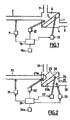
- the installation represented at figure 1 comprises a separation chamber 1 in which a physical medium is separated into a vehicle medium and a medium to be separated, by means of a separation means 3 which divides the chamber 1 into at least two chambers 4 and 6, a first chamber 6 constituting a volume in which the vehicle medium accumulates and a second chamber 4 constituting a volume in which the medium to be separated is concentrated.
- the separation means 3 is for example a filtration membrane or micro filtration, or nano filtration, or an osmotic membrane.
- a fluid mixture inlet device 2 makes it possible to introduce the physical medium into the separation chamber 1 and opens, in general, into the first chamber 6 in which the medium to be separated is concentrated.
- This fluid mixture inlet device 2 consists, for example, of a pipe, a pump and a valve.
- a carrier fluid evacuation device 8 provides regulated evacuation of the current of the vehicle medium.
- This device consists, for example, of a pipe provided with a controlled valve and / or a discharge pump.
- a complementary constituent discharge device 9 ensures a controlled current of the medium to be separated.
- This device consists for example of a pipe and a controlled valve and / or a discharge pump.
- the installation further comprises a device 11 for causing a first periodic phenomenon to act on the physical medium in the fluid mixture inlet device 2; a second device 12 for causing a second vibratory phenomenon to act on the physical medium in the first chamber 6, a third device 13 for causing a third periodic phenomenon to act on the separation means 3.
- a source of supply that can be adjusted by means electronic control device 10a of external periodic action (vibratory), the devices 11, 12 and 13 intended to act periodic phenomena on the physical medium and on the separation means 3.
- the physical medium may consist of a liquid medium, gaseous or mixed, in whose composition can enter liquids, gases, colloidal or solid bodies or combinations thereof.
- the medium to be separated may consist of organic and / or non-organic substances of liquid, gaseous, colloidal and solid type or combinations of such substances.
- the separation system 3 can be formed of at least one device or element for membrane filtration, nanofiltration, reverse osmone, a liquid system and emulsion membrane or combinations of these devices, elements and systems, and also a system of mechanical, ultrasonic, electrical and / or magnetic separation or combination of such systems.
- the arrangement of the system 3 relative to the horizontal (or the base of the device) can be any: horizontal, vertical or at any angle.
- the separation system 3 is in the form of a cylinder, for example, forming a rotating part of a centrifuge, the chamber 6 into which the current of the physical medium is introduced and in which the medium to be separated is then concentrated. is located inside this cylinder, while the chamber 4 for collecting the vehicle medium is located outside this cylinder.
- the devices 11, 12 and 13 for effecting periodic phenomena may be in the form of at least one ultrasonic action device, for example a siren, a whistle, a piezoelectric vibrator or a combination thereof.
- the power supply system 10 provides the necessary operating speeds of the devices 11, 12 and 13 intended to act on periodic phenomena, and comprises the regulator 10a make it possible to vary the frequencies and the amplitudes of energy as a function of the operating regimes. of these devices.
- the systems 10 and 10a can regulate the flow rate of the device by varying the frequency and the amplitude of the periodic actions on the treated media and on the devices for regulating the evacuation of these media.
- a source of energy it is possible to use the streams of the treated medium and of the vehicle medium. This is the case, in particular, when the devices intended to act a periodic phenomenon are whistles or sirens.
- the first and second periodic phenomena acting on the physical medium have frequencies which, preferably, are in a ratio greater than 10. That is to say, that the frequency of the second phenomenon is more than 10 times greater than the frequency of the first phenomenon, or the frequency of the first phenomenon is more than 10 times higher than the frequency of the second phenomenon.
- the devices 11, 12 and 13 for operating periodic phenomena can correspond to one and the same periodic phenomenon.
- the physical medium interacts with the separation system 3 to which a vibratory action is applied, ensuring the conditions of its self-cleaning and its uninterrupted operation in stationary mode; for example, the surface of the separation system 3 is subjected to the action of vortex currents, created by a rotating disk of determined configuration.
- the vehicle medium obtained as a result of the separation and cleaning is discharged from the separation chamber 1 by the carrier fluid evacuation device 8, in a controlled regime.
- the device comprises a separation chamber 21 in which a physical medium is separated into a vehicle medium and a medium to be separated, by means of a separation means 23 which divides the enclosure 21 into at least two chambers 24 and 26, the chamber 24 constituting a volume in which the vehicle medium and the chamber 26 constituting a volume in which the medium to be separated is concentrated.
- the separation means 23 consists of a means of micronization and spraying 23a of the physical medium which is, for example, an injector, and a condensing means 23b.
- a fluid mixing inlet device 22 makes it possible to introduce the physical medium into the separation chamber 21 and opens into the chamber 26 through the micronization and spraying device 23a so that the physical medium enters the chamber.
- the fluid mixture inlet device 22 consists for example of a pipe, a pump and a valve.
- a carrier fluid evacuation device 28 provides controlled evacuation of the vehicle medium current.
- This device consists for example of a pipe provided with a controlled valve and / or a discharge pump.
- a complementary constituent discharge device 29 ensures a regulated current of the medium to be separated.
- This device consists for example of a pipe and a controlled valve and / or a discharge pump.
- the installation further comprises a device 31 for causing a first periodic phenomenon to act on the physical medium in the fluid mixture inlet device 22; a second device 32 for causing a second vibratory phenomenon to act on the physical medium is associated with the micronization and spraying means 23a; a third device 33 for effecting a third periodic phenomenon is associated with the cooling means 23b; finally, a fourth device 34 intended to cause a fourth periodic phenomenon to act in the second chamber 24.
- a source of supply 30 that can be adjusted by means of an electronic control device 30a of external periodic action (vibratory), supplies the devices 31, 32, 33 and 34 for effecting periodic phenomena on the physical medium and on the means 23a and 23b of the separation device 23.
- the micronization and spraying means 23a with a fine dispersion of the physical medium is, for example, a mechanical and / or acoustic sprayer which disperses and injects the physical medium in the form of steam and / or aerosol with Particle size (droplets) of the molecular level (below one micron).
- the condensing means 23b is, for example, a static baffle or a dynamic baffle constituted by a means such as a whistle or a siren generating a pulsating flow of the fluid, or a means of cooling or freezing.
- this means can be a vibratory means as described in the French patent application published under the number FR 28 02118 .
- the separation device 23 is a system consisting on the one hand of an injector 23a and an acoustic micronizer chamber, which sprays the fine-dispersion physical medium and on the other hand a condensing means 23b, the first Chamber 26 is a reservoir in which the medium to be separated is concentrated and the chamber 24 is a reservoir for the carrier or carrier medium.
- Each of the vibratory action systems 31, 32, 33 and 34 may consist of at least one device of mechanical type, for example a mechanical vibrator or an ultrasonic action device, for example a siren, a whistle, a piezoelectric vibrator, or a device creating an electromagnetic or magnetic field or a radiation of corresponding configuration and intensity, or finally different combinations of the devices and systems listed above.
- a mechanical vibrator or an ultrasonic action device for example a siren, a whistle, a piezoelectric vibrator, or a device creating an electromagnetic or magnetic field or a radiation of corresponding configuration and intensity, or finally different combinations of the devices and systems listed above.
- the power supply system 30 provides the essential operating regimes of the vibratory systems 31, 32, 33 and 34 and comprises the regulator 30a make it possible to vary the frequencies and the amplitudes of energy as a function of the operating speeds of these vibratory systems. In this way, the systems 30 and 30a can regulate the flow rate of the device by varying the frequency and the amplitude of the periodic actions on the treated media and on the regulating devices. Evacuation of these media As a source of energy, it is possible to use the currents of the physical medium and the vehicle medium.
- the physical medium may consist of a liquid, gaseous or mixture medium, into which liquid, gas, colloidal and solid bodies or combinations thereof may enter.
- the medium to be separated (elements and bodies to be separated) may consist of organic and / or non-organic bodies of liquid, gaseous, colloidal or solid type or of their combination.
- the regulated current of the physical medium arriving via the fluid mixture inlet device 22 is admitted into the micronization and spraying means 23a; during its displacement, the current of the physical medium is subjected to at least one vibratory action 31 immediately before its penetration into the micronization and spraying means 23a, for example by means of microwave radiation, which creates a complementary condition favorable to the treatment of the physical medium in the micronization and spraying means 23a; then, the physical medium is micronized and pulverized by the micronization and spraying means 23a by means of the corresponding periodic action 32.
- Actions 31 and 32 above establish the necessary and sufficient conditions for spraying the fine-dispersion physical medium in the form of microparticle vapor and prepare it for the rapid cooling and / or freezing process in the refrigerating medium 23b .
- the fine dispersed particles of cooled and / or frozen vehicle medium enter the chamber 24 in which they melt under the action of a periodic radiation 34, for example a microwave or a other thermal radiation and are discharged using the carrier fluid discharge device 28 in a controlled regime.
- a periodic radiation 34 for example a microwave or a other thermal radiation
- the particles of the medium to be separated for example water with a high concentration of salt, whose freezing temperature differs considerably from the freezing temperature of the vehicle medium, are concentrated in the chamber 26 and are discharged out of the system by the complementary constituent evacuation device in the regulated regime.
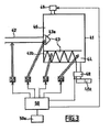
- FIG 3 is represented the diagram of an installation implementing a process of desalination of seawater by the separation of salt water (physical medium or fluid mixture) in a vehicle medium (purified water) and a medium to be separated ( water with a very high concentration of salt), using at least one separation means, according to the invention.
- salt water physical medium or fluid mixture
- vehicle medium purified water
- medium to be separated water with a very high concentration of salt
- the installation represented at figure 3 comprises a separation chamber 41 in which a controlled current of seawater supplied by a fluid mixture inlet device 42 is separated into a vehicle medium and a medium to be separated.
- the separation chamber 41 comprises at least one vibratory separation means 43 for the salted water in carbonated water (vaporized) and salt water having a higher concentration of salt, and at least two chambers 44 and 46 in which penetrate and are treated salt water, the vehicle medium and the medium to be separated respectively.
- the separating means 43 is a vibratory means. It consists of a vibration vibratory device 43a and a vibration vibrating means 43b.
- At least one device for discharging the carrier fluid 48 ensures the translation of the gasified (vaporized) water molecules supplemented by a device 48a ensuring the evacuation of the regulated current from the vehicle medium and the condensation of the gasified water molecules (vaporized) to form a purified liquid medium (pure water).
- At least one evacuation device of the complementary constituent 49 ensures the evacuation of the regulated current from the medium to be separated.
- the vibration vibratory device 43a disposed at the outlet of the fluid mixing inlet device 42 in the chamber 46 vaporizes the seawater which enters the separation chamber.
- the vibratory condensation means 43b disposed between the chambers 44 and 46, makes it possible to separate the vehicle medium (pure water vapor) and the medium to be separated (water very heavily loaded with salt).
- Means for causing a periodic phenomenon to act 53, 54 make it possible to act a periodic phenomenon on the vehicle medium and the medium to be separated.
- the means for operating a periodic phenomenon 51, 52, 53 and 54 are controlled by at least one power source 50 adjustable by electronic adjustment means 50a.
- the regulated stream of seawater inlet can also be naturally or artificially salted water, or else water in the composition of which can enter different liquid components, gases, colloidal bodies or solids or their combinations.
- the carrier medium may consist of gasified water molecules (vaporized), fine droplets of water and pulsed air (repressed).
- the pulsed air may be constituted by elements providing cooling and / or freezing the gasified water molecules (vaporized) obtained by the vibratory treatment 54.
- the medium to be separated may consist of concentrated salt water and salt crystals as well as the composition of which can enter different liquid components, gases, colloidal or solid corns or combinations thereof.
- a device for operating a periodic phenomenon 53 represents a device for cooling and / or freezing pure water molecules. It is a conventional freezing system and / or a refrigerant, easily separable subsequently vehicle medium.
- An evacuation device of the carrier fluid 48 ensures the translation of the gasified water molecules (vaporized). It consists for example of a regulated vacuum fan, and / or at least one suction pneumatic pump, or together. It is completed by a device 48a ensuring the evacuation of the controlled current of the vehicle medium, consisting for example of a controlled valve and / or a centrifugal extraction pump for the condensation of gasified water molecules.
- a complementary component evacuation device 49 ensuring the evacuation of the regulated current of the medium to be separated consists for example of a regulated valve and / or a hydraulic drain pump.
- Each of the devices making it possible to act on periodic phenomena 51, 52, 53 and 54 may consist of at least one device of the mechanical type, for example a hydraulic, pneumatic or mixed pump, or at least one device.
- ultrasonic action for example a siren, a whistle, a piezoelectric vibrator, or at least one device creating an electromagnetic or magnetic field, or a thermal radiation of corresponding configuration and intensity, or finally different combinations of devices and systems mentioned above.
- the feed device 50 provides the necessary operating regimes of the devices for operating periodic phenomena 51, 52, 53 and 54, as well as spraying devices 43a and separation 43b. It further comprises the regulator 50a allow to vary the frequencies and powers (energy expenses) according to the operating regimes of the systems mentioned that it feeds and manages. In this way, the feed device 50 and control device 50a can provide flow control of the device by varying the frequency and amplitude of the vibratory actions on the treated media, as well as the regulation of the working patterns of the evacuation devices carrier fluid 48 and the complementary constituent 49 ensuring the translation and evacuation of these media. As a source of energy, it is also possible to use the streams of the treated medium and the vehicle medium and the medium to be separated, for example to feed the sirens and whistles.
- the regulated current of seawater is admitted into the micronization and spraying device 43a.
- the current of the seawater may be subjected to at least one vibratory action 51, immediately before its penetration into the spraying device 43a, for example by means of thermal radiation (less than 100 ° C), which creates a favorable condition favorable to the treatment of seawater in the spraying device 43a performing its micronization and spraying in the chamber 46.
- gasified water for example cold vapor (less than 100 ° C) and fine droplets of saline water (less than 1 micron) prepared for treatment in separating device 43b.
- the vehicle medium (pure water) obtained by the actions cited is evacuated using the device for discharging the vehicle medium, 48 and 48a, in a controlled regime.
- the droplets of the medium to be separated for example water with a high concentration of salt, whose freezing temperature differs considerably from the freezing temperature of the vehicle medium, are concentrated at the bottom in the chamber 44 and are discharged out of the system by the device for evacuating the complementary constituent 49, in regulated mode.
- condensation device 48a for example in at least one condensation chamber of a centrifugal pump.
- condensation device 48a for example in at least one condensation chamber of a centrifugal pump.
- the use of devices to act periodic phenomena 53 and 54 to ensure freezing and warming is not necessary.
- the present invention uses a method of simultaneous action on a physical medium and / or on a medium to be separated using at least two periodic actions, as described previously in the French patent.
- FR-A-2,744,931 the same applicants.
- the implementation of at least two periodic actions on the treated media is used not for their mixing, but for their separation and concentration.
- a resonant cavitation is produced, which breaks the molecules of the physical medium into constituents, for example into molecules of the carrier medium and of the medium to be separated.
- the molecules of the carrier medium and the medium to be separated are then present in unbound form thanks to their resonant excitation.
Abstract
Description
L'invention est relative à la séparation d'un mélange fluide en un fluide porteur et un constituant complémentaire.The invention relates to the separation of a fluid mixture into a carrier fluid and a complementary component.
Les mélanges fluides correspondent à des milieux physiques très divers comprenant plusieurs constituants. Ces mélanges fluides peuvent être homogènes, c'est-à-dire constitués d'une seule phase liquide ou gazeuse, ou hétérogènes, c`est-à-dire constitués d'au moins une phase liquide ou gazeuse et au moins une deuxième phase liquide, gazeuse, solide ou colloïdale.The fluid mixtures correspond to very diverse physical media comprising several constituents. These fluid mixtures may be homogeneous, that is to say consist of a single liquid or gaseous phase, or heterogeneous, that is to say consist of at least one liquid or gaseous phase and at least one second phase liquid, gaseous, solid or colloidal.
Pour de nombreuses applications, on cherche à séparer les constituants d'un mélange fluide en d'une part un fluide porteur et d'autre part un constituant complémentaire. Pour cela, on utilise des procédés divers tels que la filtration sur membrane, la nano et la micro filtration, l'osmose inverse, l'émulsion à membrane liquide et leurs combinaisons, ainsi que les procédés de séparation mécanique, ultrasonore, électrique, magnétique et mixte (par exemple électromagnétique) ou encore les procédés de distillation.For many applications, it is sought to separate the constituents of a fluid mixture on the one hand a carrier fluid and on the other hand a complementary component. For this, various methods are used such as membrane filtration, nano and microfiltration, reverse osmosis, liquid membrane emulsion and combinations thereof, as well as mechanical, ultrasonic, electrical, magnetic separation processes. and mixed (for example electromagnetic) or distillation processes.
Les mélanges fluides considérés étant très divers, par la suite, on utilisera également l'expression « milieu physique » pour désigner un « mélange fluide », « milieu véhicule » pour désigner un « fluide porteur » et « milieu à séparer » pour désigner un « constituant complémentaire ».The fluid mixtures considered being very diverse, subsequently, the term "physical medium" will also be used to designate a "fluid mixture", "vehicle medium" to designate a "carrier fluid" and "medium to be separated" to designate a "Complementary constituent".
On connaît des procédés et des dispositifs de séparation de milieux physiques par filtration statique et dynamique. Ils reposent sur les principes de base suivants :
- on sépare le volume du dispositif par un dispositif de séparation par exemple un filtre, en deux zones, dans l'une desquelles, au moyen d'une source de puissance de nature statique ou impulsionnelle, on exerce une action sur le milieu physique, par exemple une pression au moyen d'une pompe de remplissage grâce à quoi, on crée une différence de pression sur les côtés opposés du filtre,
- on agit sur le dispositif de séparation, par exemple le filtre, par une action complémentaire, par exemple, à l'aide de courants inverses de liquide et on nettoie de ce fait, les pores de la surface du filtre, en la débarrassant des éléments qui l'obturent et qui bloquent son fonctionnement,
- on sépare par les actions indiquées plus haut, le milieu physique (à purifier) en un milieu véhicule (purifié) et les éléments à séparer et on les évacue séparément hors du dispositif.
- the volume of the device is separated by a separation device, for example a filter, into two zones, in one of which, by means of a source of power of a static or impulse nature, an action is exerted on the physical medium, for example for example a pressure by means of a filling pump whereby a pressure difference is created on the opposite sides of the filter,
- the separation device, for example the filter, is acted on by a complementary action, for example, using reverse currents of liquid, and cleans the pores of the surface of the filter, by removing the elements which close it and which block its operation,
- the physical medium (to be purified) is separated by means of the actions indicated above into a carrier medium (purified) and the elements to be separated and is separately removed from the device.
Les inconvénients essentiels des procédés et dispositifs existants de purification et de séparation des milieux physiques sont les suivants :
- dépenses d'énergie importantes pour la purification des milieux physiques,
- faible durée de vie des systèmes de séparation, par exemple des filtres et nécessité de leurs remplacements fréquents lors de la mise en oeuvre de procédés statiques de filtration,
- la régénération des systèmes de séparation, par exemple des filtres donne lieu à d'importantes dépenses complémentaires, matérielles et énergétiques, conditionnées par la création de vitesses élevées et/ou de courants tourbillonnaires le long des surfaces des filtres à nettoyer,
- action destructive des courants tourbillonnaires à grande vitesse sur les éléments à séparer (à purifier), dans le cas de la nécessité de leur utilisation ultérieure,
- faible rendement nominal des dispositifs, dû à l'obturation progressive des pores des filtres et à la nécessité d'utilisation de matériaux ayant des pores de diamètre réduit pour réduire la vitesse de leur obturation,
- importantes dépenses en temps pour le nettoyage des systèmes de séparation, par exemple des filtres, dues à la réduction de leur rendement nominal lors de leur fonctionnement ininterrompu en raison du dépôt des éléments à séparer sur les surfaces du filtre et dans ses pores.
- significant energy expenditure for the purification of physical environments,
- low service life of separation systems, for example filters and the need for their frequent replacements during the implementation of static filtration processes,
- the regeneration of the separation systems, for example filters, gives rise to significant additional expenditure, material and energy, conditioned by the creation of high speeds and / or vortex currents along the surfaces of the filters to be cleaned,
- destructive action of swirling currents at high speed on the elements to be separated (to be purified), in the case of the necessity of their subsequent use,
- low nominal efficiency of the devices, due to the gradual clogging of the pores of the filters and the need for the use of materials having pores of reduced diameter in order to reduce the shutter speed,
- significant expense in time for cleaning separation systems, for example filters, due to the reduction of their nominal efficiency during their uninterrupted operation due to the deposition of the elements to be separated on the filter surfaces and in its pores.
On connaît également un procédé et des dispositifs de séparation de milieux physiques par distillation.Also known is a method and devices for separating physical media by distillation.
Ils reposent sur la modification de l'état d'un milieu physique, par exemple liquide, par son échauffement, son évaporation et son refroidissement.They are based on the modification of the state of a physical environment, for example liquid, by its heating, evaporation and cooling.
Les inconvénients essentiels de ce procédé et des dispositifs pour sa mise en oeuvre sont les suivants :
- efficacité et rendement faibles, dus à des dépenses importantes en énergie et en milieu physique,
- construction complexe,
- durée de cycle importante,
- coût élevé des installations et de leur exploitation,
- low efficiency and efficiency, due to high energy and physical expenditure,
- complex construction,
- long cycle time,
- high cost of the facilities and their operation,
Le but de la présente invention est de remédier à ces inconvénients en proposant un moyen pour purifier un milieu physique ayant un rendement amélioré et nécessitant des dépenses en temps et énergie sensiblement réduites.The object of the present invention is to overcome these disadvantages by providing a means for purifying a physical medium having improved performance and requiring significantly reduced time and energy expenditure.
A cet effet, l'invention a pour objet un procédé de séparation d'un mélange fluide en un fluide porteur et un constituant complémentaire à l'aide d'une installation de séparation constituée d'un dispositif d'arrivée de mélange fluide, d'une enceinte de séparation comportant une première chambre, une deuxième chambre et un moyen de séparation, d'un dispositif d'évacuation de fluide porteur et d'un dispositif d'évacuation du constituant complémentaire, selon lequel on envoie un courant de mélange fluide dans le dispositif d'arrivée de mélange fluide de façon à l'introduire dans la première chambre, à l'aide du moyen de séparation on sépare le mélange fluide en un fluide porteur qui est recueilli dans la deuxième chambre et un constituant complémentaire qui reste dans la première chambre, et on évacue le fluide porteur par le dispositif d'évacuation du fluide porteur et le constituant complémentaire par le dispositif d'évacuation du constituant complémentaire. Selon l'invention, dans le dispositif d'arrivée de mélange fluide, on soumet le courant de mélange fluide à l'action d'au moins un premier phénomène périodique ayant une première fréquence, et, dans la première chambre, on soumet le mélange fluide à l'action d'au moins un deuxième phénomène périodique ayant une deuxième fréquence, les fréquences du premier phénomène périodique et du deuxième phénomène périodique étant dans un rapport supérieur à 10, et on régule le débit d'arrivée du mélange fluide, le débit d'évacuation du fluide porteur et le débit d'évacuation du constituant complémentaire. Les phénomènes périodiques utilisés peuvent être de différent type, et, en particulier, du type mécanique, acoustique, ultrasonique, thermique, électrique, magnétique ou mixtes par exemple électromagnétique, électromécaniques etc.For this purpose, the subject of the invention is a process for separating a fluid mixture into a carrier fluid and a complementary constituent by means of a separation device consisting of a fluid mixture inlet device, a a separation chamber comprising a first chamber, a second chamber and a separation means, a carrier fluid evacuation device and a device for discharging the complementary constituent, according to which a flow of fluid mixture is sent. in the fluid mixture inlet device so as to introduce it into the first chamber, by means of the separation means the fluid mixture is separated into a carrier fluid which is collected in the second chamber and a complementary component which remains in the first chamber, and the carrier fluid is evacuated by the evacuation device of the carrier fluid and the complementary constituent by the evacuation device of the complementary constituent. to hush up. According to the invention, in the fluid mixture inlet device, the fluid mixing stream is subjected to the action of at least a first periodic phenomenon having a first frequency, and in the first chamber, the mixture is subjected to fluid to the action of at least one second periodic phenomenon having a second frequency, the frequencies of the first periodic phenomenon and the second periodic phenomenon being in a ratio greater than 10, and the flow rate of arrival of the fluid mixture is controlled, the discharge rate of the carrier fluid and the discharge rate of the complementary constituent. The periodic phenomena used may be of different type, and in particular of the mechanical, acoustic, ultrasonic, thermal, electrical, magnetic or mixed type for example electromagnetic, electromechanical etc.
En outre, on peut soumettre au moins le moyen de séparation à l'action d'au moins un troisième phénomène périodique.In addition, at least one third periodic phenomenon can be subjected to at least one of the separation means.
De préférence, on régule en fréquence et /ou en amplitude les différents phénomènes périodiques utilisés, en fonction d'au moins un des débits de mélange fluide, de fluide porteur et de constituant complémentaire.Preferably, the different periodic phenomena used are regulated in frequency and / or in amplitude as a function of at least one of the fluid mixture, carrier fluid and complementary constituent flow rates.
Le moyen de séparation peut comporter au moins une membrane.The separation means may comprise at least one membrane.
Lors de l'introduction du mélange fluide dans la première chambre, on peut également pulvériser finement ou microniser ledit mélange fluide de façon à produire un milieu constitué de particules dont les dimensions sont inférieures au micron, et, à l'aide de phénomènes périodiques, on condense lesdites particules, et on sépare le fluide porteur et le constituant complémentaire. Pour faciliter la pulvérisation ou la micronisation du mélange fluide, on peut soumettre le mélange fluide à l'action d'un phénomène périodique du type micro-ondes ou ultrason, ou encore leur combinaison. Pour séparer le mélange fluide micronisé en fluide porteur et constituant complémentaire, on peut créer des vagues de flux de fluide porteur à l'aide d'au moins une action périodique formée par un dispositif de condensation constitué d'une chicane. Ce procédé s'applique notamment au dessalement de l'eau de mer, et dans ce cas le mélange fluide est de l'eau de mer, le fluide porteur est de l'eau douce et l'élément complémentaire est de l'eau à forte concentration en sel.When introducing the fluid mixture into the first chamber, it is also possible to finely spray or micronize said fluid mixture so as to produce a medium consisting of particles whose dimensions are smaller than one micron, and, with the aid of periodic phenomena, said particles are condensed, and the carrier fluid and the complementary constituent are separated. To facilitate the spraying or micronization of the fluid mixture, the fluid mixture can be subjected to the action of a periodic phenomenon of the microwave or ultrasound type, or their combination. To separate the micronized fluid mixture into a carrier fluid and a complementary component, waves of carrier fluid flow can be created by means of at least one periodic action formed by a condensation device consisting of a baffle. This process is particularly applicable to the desalination of seawater, and in this case the fluid mixture is seawater, the carrier fluid is fresh water and the complementary element is water to high concentration of salt.
L'invention concerne également une installation pour la mise en oeuvre du procédé de séparation selon l'invention. Cette installation comprend un dispositif d'arrivée de mélange fluide, une enceinte de séparation, un dispositif d'évacuation de fluide porteur et d'un dispositif d'évacuation du constituant complémentaire, ladite enceinte de séparation comportant une première chambre, une deuxième chambre et un moyen de séparation. En outre, le dispositif d'arrivée de mélange fluide comprend au moins un dispositif pour faire agir au moins un premier phénomène périodique, et au moins la première chambre comporte au moins un dispositif pour faire agir au moins un deuxième phénomène périodique. Le dispositif selon l'invention comprend également des moyens de commande et de régulation du dispositif d'arrivée de mélange fluide, du dispositif d'évacuation du fluide porteur, du dispositif d'évacuation du constituant complémentaire, et des dispositifs destinés à faire agir les au moins un premiers et deuxièmes phénomènes périodiques.The invention also relates to an installation for implementing the separation method according to the invention. This installation comprises a fluid mixture inlet device, a separation chamber, a carrier fluid evacuation device and a device for discharging the complementary component, said separation chamber comprising a first chamber, a second chamber and a means of separation. In addition, the fluid mixture inlet device comprises at least one device for acting at least a first periodic phenomenon, and at least the first chamber comprises at least one device for causing at least one second periodic phenomenon. The device according to the invention also comprises means for controlling and regulating the fluid mixture inlet device, the carrier fluid evacuation device, the complementary constituent evacuation device, and devices for causing the at least first and second periodic phenomena to act.
Au moins un dispositif pour faire agir un phénomène périodique peut être, par exemple, un sifflet ou une sirène animés par le courant d'entée du mélange fluide.At least one device for effecting a periodic phenomenon may be, for example, a whistle or a siren animated by the flow current of the fluid mixture.
L'installation selon l'invention peut comprendre au moins un moyen pour faire agir un phénomène périodique électromagnétique et/ou thermique sur le courant d'arrivée de mélange fluide, au moins un moyen pour faire agir un phénomène périodique mécanique ou ultrasonore, un moyen de pulvérisation afin de microniser et de pulvériser sous forme de vapeur et/ou d'aérosol le mélange fluide, un moyen de condensation du mélange fluide en un fluide porteur et un constituant complémentaire du type comprenant au moins un moyen tel qu'une chicane statique, une chicane dynamique générée par un sifflet ou une sirène, ou un moyen agissant par refroidissement ou congélation, et un moyen pour faire agir un phénomène périodique du type électromagnétique et/ou thermique pour réchauffer le fluide porteur. En outre, elle peut comprendre des moyens pour évacuer le fluide porteur et des moyens pour évacuer le constituant complémentaire, constitués de pompes aspirantes et de vannes régulatrices, et des moyens d'alimentation et de régulation des moyens pour faire agir les phénomènes périodiques.The installation according to the invention may comprise at least one means for causing a periodic electromagnetic and / or thermal phenomenon to act on the fluid mixture inlet stream, at least one means for causing a mechanical or ultrasonic periodic phenomenon to act, a means for spraying method for micronizing and spraying in the form of vapor and / or aerosol the fluid mixture, a means for condensing the fluid mixture into a carrier fluid and a complementary component of the type comprising at least one means such as a static baffle , a dynamic baffle generated by a whistle or a siren, or a means acting by cooling or freezing, and a means for causing a periodic phenomenon of the electromagnetic and / or thermal type to heat the carrier fluid. In addition, it may comprise means for evacuating the carrier fluid and means for discharging the complementary constituent, consisting of suction pumps and regulating valves, and means for supplying and regulating the means for causing the periodic phenomena to act.
L'invention va maintenant être décrite plus en détail en regard des figures annexées, dans lesquelles :
- la
figure 1 représente schématiquement une installation de séparation d'un milieu physique tel qu'un mélange fluide, mettant en oeuvre un procédé de séparation par membrane, - la
figure 2 représente schématiquement une installation de séparation d'un milieu physique tel qu'un mélange fluide, mettant en oeuvre un procédé de séparation par pulvérisation,
- the
figure 1 schematically represents a separation plant of a physical medium such as a fluid mixture, implementing a membrane separation process, - the
figure 2 schematically represents an installation for separating a physical medium such as a fluid mixture, implementing a sputter separation process,
L'installation représentée à la
Le milieu physique peut être constitué d'un milieu liquide, gazeux ou mélangé, dans la composition duquel peuvent entrer des liquides, des gaz, des corps colloïdaux ou solides ou leurs combinaisons.The physical medium may consist of a liquid medium, gaseous or mixed, in whose composition can enter liquids, gases, colloidal or solid bodies or combinations thereof.
Le milieu à séparer (éléments et corps à séparer) peut être constitué par des substances organiques et/ou non organiques de type liquide, gazeux, colloïdal et solide ou de combinaisons de telles substances.The medium to be separated (elements and bodies to be separated) may consist of organic and / or non-organic substances of liquid, gaseous, colloidal and solid type or combinations of such substances.
Le système de séparation 3 peut être formé d'au moins un dispositif ou élément de filtration à membrane, de nanofiltration, d'osmone inverse, d'un système à liquide et membrane à émulsion ou de combinaisons de ces dispositifs, éléments et systèmes, et également d'un système de séparation mécanique, ultrasonore, électrique ou/et magnétique ou de combinaison de tels systèmes.The
La disposition du système 3 par rapport à l'horizontale (ou de la base du dispositif) peut être quelconque : horizontale, verticale ou sous un angle quelconque.The arrangement of the
Si le système de séparation 3 est réalisé sous la forme d'un cylindre, par exemple, formant une pièce tournante d'une centrifugeuse, la chambre 6 dans laquelle est introduit le courant du milieu physique et dans laquelle est ensuite concentré le milieu à séparer, se trouve à l'intérieur de ce cylindre, tandis que la chambre 4 destinée à la collecte du milieu véhicule se trouve à l'extérieur de ce cylindre.If the
Les dispositifs 11, 12 et 13 destinés à faire agir des phénomènes périodiques, peuvent se présenter sous la forme d'au moins un dispositif d'action ultrasonore, par exemple une sirène, un sifflet, un vibrateur piézo-électrique ou leur combinaison, d'au moins un dispositif de type à magnétostriction, un dispositif de type magnétique ou électromagnétique, créant par exemple un champ magnétique ou électromagnétique de configuration ou d'intensité correspondante, ou, enfin, de différentes combinaisons des dispositifs et systèmes énumérés plus haut. Le système d'alimentation 10 assure les régimes de fonctionnement indispensables des dispositifs 11,12 et 13 destinés à faire agir des phénomènes périodiques, et comprend le régulateur 10a permettent de faire varier les fréquences et les amplitudes d'énergie en fonction des régimes de fonctionnement de ces dispositifs. De cette manière les systèmes 10 et 10a peuvent assurer la régulation du débit du dispositif par variation de la fréquence et de l'amplitude des actions périodiques sur les milieux traités et sur les dispositifs de régulation de l'évacuation de ces milieux. En qualité de source d'énergie, on peut utiliser les courants du milieu traité et du milieu véhicule. C'est le cas, en particulier, lorsque les dispositifs destinés à faire agir un phénomène périodique sont des sifflets ou des sirènes.The
Les premiers et deuxième phénomènes périodiques agissant sur le milieu physique ont des fréquences qui, de préférence, sont dans un rapport supérieur à 10. C'est-à-dire, que la fréquence du deuxième phénomène est plus de 10 fois supérieure à la fréquence du premier phénomène, ou bien, la fréquence du premier phénomène est plus de 10 fois supérieure à la fréquence du deuxième phénomène.The first and second periodic phenomena acting on the physical medium have frequencies which, preferably, are in a ratio greater than 10. That is to say, that the frequency of the second phenomenon is more than 10 times greater than the frequency of the first phenomenon, or the frequency of the first phenomenon is more than 10 times higher than the frequency of the second phenomenon.
Les dispositifs 11, 12 et 13 permettant de faire agir des phénomènes périodiques peuvent correspondre à un seul et même phénomène périodique.The
Conformément au schéma représenté à la
- le courant régulé du milieu physique, amené par le dispositif d'arrivée de mélange fluide 2, pénètre dans la chambre 6 de l'enceinte de séparation 1 ;
- au cours de son déplacement, le milieu physique est soumis à au moins une action d'un premier phénomène périodique à l'aide du dispositif 11, immédiatement avant son introduction dans la chambre 6, et à l'action d'un deuxième phénomène périodique dans la chambre 6 elle-même à l'aide du dispositif 12. Les actions précitées créent les conditions de concentration du milieu à séparer sous l'action des vibrations mécaniques, électromagnétiques, acoustiques ou/et mixte et contribuent à son évacuation efficace à l'aide du dispositif d'évacuation de constituant complémentaire 9 en régime régulé.
- the regulated current of the physical medium, brought by the fluid mixture inlet device 2, enters the chamber 6 of the separation chamber 1;
- during its displacement, the physical medium is subjected to at least one action of a first periodic phenomenon using the
device 11, immediately before its introduction into the chamber 6, and to the action of a second periodic phenomenon in the chamber 6 itself with the aid of thedevice 12. The aforementioned actions create the conditions of concentration of the medium to be separated under the action of mechanical, electromagnetic, acoustic or / and mixed vibrations and contribute to its effective evacuation at the same time. aid of the complementary constituent evacuation device 9 in regulated mode.
Dans la chambre 6, le milieu physique entre en interaction avec le système de séparation 3 auquel est appliquée une action vibratoire, assurant les conditions de son auto-nettoyage et de son fonctionnement ininterrompu en régime stationnaire; par exemple, la surface du système de séparation 3 est soumise à l'action de courants tourbillonnaires, crées par un disque tournant de configuration déterminée.In the chamber 6, the physical medium interacts with the
Le milieu véhicule obtenu du fait de la séparation et du nettoyage est évacué hors de l'enceinte de séparation 1 par le dispositif d'évacuation de fluide porteur 8, en régime régulé.The vehicle medium obtained as a result of the separation and cleaning is discharged from the separation chamber 1 by the carrier fluid evacuation device 8, in a controlled regime.
Dans un deuxième mode de réalisation, représenté à la
Le moyen de micronisation et de pulvérisation 23a à fine dispersion du milieu physique est par exemple un pulvérisateur mécanique et/ou acoustique qui disperse et injecte le milieu physique sous forme de vapeur et/ou d'aérosol avec des dimensions de particules (gouttelettes) du niveau moléculaire (inférieures au micron).The micronization and spraying means 23a with a fine dispersion of the physical medium is, for example, a mechanical and / or acoustic sprayer which disperses and injects the physical medium in the form of steam and / or aerosol with Particle size (droplets) of the molecular level (below one micron).
Le moyen de condensation 23b est, par exemple, une chicane statique ou une chicane dynamique constituée par un moyen tel qu'un sifflet ou une sirène engendrant un écoulement pulsé du fluide, ou encore, un moyen de refroidissement ou de congélation. Lorsque le moyen de condensation 23b est un moyen de refroidissement et/ou de congélation, ce moyen peut être un moyen vibratoire tel que décrit dans la demande de brevet français publiée sous le numéro
Dans ce cas, le processus traditionnel d'évaporation coûteux et consommant de l'énergie est remplacé par une technologie d'injection à faible dispersion qui se caractérise par une demande d'énergie et de temps des dizaines de fois plus faible.In this case, the traditional process of expensive evaporation and consuming energy is replaced by a low dispersion injection technology that is characterized by a demand of energy and time tens of times lower.
Ainsi, le dispositif de séparation 23 est un système constitué d'une part d'un injecteur 23a et d' une chambre acoustique de microniseur, qui pulvérise le milieu physique à dispersion fine et d'autre part un moyen de condensation 23b, la première chambre 26 est un réservoir dans lequel est concentré le milieu à séparer et la chambre 24 est un réservoir pour le milieu véhicule ou porteur.Thus, the
Chacun des systèmes d'action vibratoire 31, 32, 33 et 34 peut être constitué d'au moins un dispositif de type mécanique, par exemple un vibreur mécanique ou d'un dispositif d'action ultrasonore, par exemple une sirène, un sifflet, un vibreur piézo-électrique, ou d'un dispositif créant un champ électromagnétique ou magnétique ou un rayonnement de configuration et d'intensité correspondante ou enfin de différentes combinaisons des dispositifs et systèmes énumérés plus haut.Each of the
Le système d'alimentation 30 assure les régimes indispensables de fonctionnement des systèmes vibratoires 31, 32, 33 et 34 et comprend le régulateur 30a permettent de faire varier les fréquences et les amplitudes d'énergie en fonction des régimes de fonctionnement de ces systèmes vibratoires. De cette manière les systèmes 30 et 30a peuvent assurer la régulation du débit du dispositif par variation de la fréquence et de l'amplitude des actions périodiques sur les milieux traités et sur les dispositifs de régulation de l'évacuation de ces milieux En qualité de source d'énergie, on peut utiliser les courants du milieu physique et du milieu véhicule.The
Le milieu physique peut être constitué d'un milieu liquide, gazeux ou d'un mélange, dans la composition duquel peuvent entrer des liquides, des gaz, des corps colloïdaux et solides ou des combinaisons de ceux-ci. Le milieu à séparer (éléments et corps à séparer) peut être constitué par des corps organiques et/ou non organiques de type liquide, gazeux, colloïdal ou solide ou de leur combinaison.The physical medium may consist of a liquid, gaseous or mixture medium, into which liquid, gas, colloidal and solid bodies or combinations thereof may enter. The medium to be separated (elements and bodies to be separated) may consist of organic and / or non-organic bodies of liquid, gaseous, colloidal or solid type or of their combination.
Toujours en référence à la
Le courant régulé du milieu physique arrivant par le dispositif d'arrivée de mélange fluide 22 est admis dans le moyen de micronisation et de pulvérisation 23a ; au cours de son déplacement, le courant de milieu physique est soumis à au moins une action vibratoire 31 immédiatement avant sa pénétration dans le moyen de micronisation et de pulvérisation 23a , par exemple au moyen d'un rayonnement à micro-ondes, ce qui crée une condition complémentaire favorable au traitement du milieu physique dans le moyen de micronisation et de pulvérisation 23a ; ensuite, le milieu physique est micronisé et pulvérisé par le moyen de micronisation et de pulvérisation 23a à l'aide de l'action périodique correspondante 32.The regulated current of the physical medium arriving via the fluid
Les actions 31 et 32 précitées établissent les conditions nécessaires et suffisantes pour une pulvérisation du milieu physique à dispersion fine, sous forme de vapeur de micro particules et elles le préparent pour le processus de refroidissement rapide et/ou de congélation dans le moyen de réfrigération 23b.
Les particules à dispersion fine du milieu véhicule refroidies et/ou congelées, par exemple d'eau pure pénètrent dans la chambre 24 dans laquelle elles fondent sous l'action d'un rayonnement périodique 34, par exemple à micro-ondes ou d'un autre rayonnement thermique et sont évacuées à l'aide du dispositif d'évacuation de fluide porteur 28 en régime régulé. Les particules du milieu à séparer, par exemple d'eau à grande concentration de sel, dont la température de congélation se distingue considérablement de la température de congélation du milieu véhicule, sont concentrées dans la chambre 26 et sont évacuées hors du système par le dispositif d'évacuation de constituant complémentaire en régime régulé.The fine dispersed particles of cooled and / or frozen vehicle medium, for example of pure water, enter the
On va maintenant décrire l'application du procédé selon l'invention au cas particulier du dessalement de l'eau de mer.The application of the process according to the invention will now be described in the particular case of desalination of seawater.
Sur la
L'installation représenté à la
A noter que le courant régulé d'entrée d'eau de mer peut également être de l'eau naturellement ou artificiellement salée, ou encore de l'eau dans la composition de laquelle peuvent entrer différents composants liquides, des gaz, des corps colloïdaux ou solides ou leurs combinaisons.It should be noted that the regulated stream of seawater inlet can also be naturally or artificially salted water, or else water in the composition of which can enter different liquid components, gases, colloidal bodies or solids or their combinations.
Le milieu véhicule peut être constitué par des molécules d'eau gazéifiées (vaporisées), des gouttelettes fines de l'eau et d'air pulsé (refoulé). L'air pulsé peut être constitué par des éléments assurant le refroidissement et/ou congélation les molécules d'eau gazéifiées (vaporisée) obtenus par le traitement vibratoire 54.The carrier medium may consist of gasified water molecules (vaporized), fine droplets of water and pulsed air (repressed). The pulsed air may be constituted by elements providing cooling and / or freezing the gasified water molecules (vaporized) obtained by the
Le milieu à séparer peut être constitué par de l'eau salée concentrée et cristaux du sel aussi que les composition duquel peuvent entrer des différents composants liquides, des gaz, des cors colloïdaux ou solides ou leurs combinaisons.The medium to be separated may consist of concentrated salt water and salt crystals as well as the composition of which can enter different liquid components, gases, colloidal or solid corns or combinations thereof.
Le dispositif de séparation 43, qui disperse et injecte l'eau salée sous forme de gaz (vapeur froide inférieure à 100°C) et des gouttelettes fines de l'eau salée avec la dimension de particules inférieures au micron, comporte :
- au moins
un dispositif 43a de micronisation et de pulvérisation à fine dispersion de l'eau salée par exemple au moins un pulvérisateur pneumatique, hydraulique et/ou mixte, ou par exemple système acoustique (vibrateur ultrasonore piézoélectrique), mécanique (sirène, soufflet), magnétique (magnétostriction), électrique (réflecteur à moteur électrique) ou encore leurs combinaisons, ou encore la combinaison des systèmes pneumatique, hydraulique mécaniques, électriques, magnétiques et acoustiques cités ; - au moins un dispositif de condensation 43b permettant la séparation définitive des molécules d'eau gazéifiées (vaporisées) et d'eau sous la forme de micro gouttelettes d'eau salées. Ce dispositif de condensation est, par exemple, un système statique tel qu'une chicane statique qui comporte une structure fixe avec une configuration ondulatoire qui forme des ondes stationnaires immobiles et qui permet de créer des vagues du flux du milieu véhicule. Il peut également être un système dynamique tel qu'une chicane dynamique qui comporte un dispositif engendrant un écoulement pulsé du milieu traité, par l'action d'une turbine à air ou d'un ventilateur, ou encore par un système mécano acoustique (par exemple sirène ou sifflet), ou leur combinaison. Le dispositif de la
condensation 43b peut encore être constitué de la combinaison de chicanes statiques et dynamiques.
- at least one device 39a for micronization and spraying with a fine dispersion of salt water, for example at least one pneumatic, hydraulic and / or mixed sprayer, or for example acoustic system (piezoelectric ultrasonic vibrator), mechanical (siren, bellows), magnetic (magnetostriction), electrical (electric motor reflector) or their combinations, or the combination of pneumatic, hydraulic, mechanical, electrical, magnetic and acoustic systems mentioned;
- at least one
condensation device 43b allowing the final separation of the gasified water molecules (vaporized) and water in the form of micro salt water droplets. This condensation device is, for example, a static system such as a static baffle which comprises a fixed structure with a wave configuration which forms stationary standing waves and which makes it possible to create waves of the flow of the vehicle medium. It can also be a dynamic system such as a dynamic chicane which has a device generating a pulsed flow of the treated medium, by the action of an air turbine or a fan, or by a mechanical acoustic system (for example siren or whistle), or their combination. Thecondensation device 43b may also consist of the combination of static and dynamic baffles.
Un dispositif permettant de faire agir un phénomène périodique 53 représente un dispositif de refroidissement et/ou de congélation des molécules d'eau pure. Il constitue un système de congélation classique et/ou un agent réfrigérant, facilement séparable par la suite de milieu véhicule.A device for operating a
Une dispositif d'évacuation du fluide porteur 48 assure la translation des molécules d'eau gazéifiées (vaporisées). Il est constitué par exemple d'un ventilateur aspirateur régulé, et/ou au moins une pompe pneumatique aspirante, ou encore par leur ensemble. Il est complété par un dispositif 48a assurant l'évacuation du courant régulé du milieu véhicule, constitué par exemple d'une vanne régulée et/ou d'une pompe d'extraction centrifuge destiné au condensation des molécules d'eau gazéifiées.An evacuation device of the
Un dispositif d'évacuation de constituant complémentaire 49 assurant l'évacuation du courant régulé du milieu à séparer, est constitué par exemple d'une vanne régulée et/ou d'une pompe hydraulique de vidange.A complementary component evacuation device 49 ensuring the evacuation of the regulated current of the medium to be separated, consists for example of a regulated valve and / or a hydraulic drain pump.
Chacun des dispositifs permettant de faire agir des phénomènes périodiques 51, 52, 53 et 54, peut être constitué d'au moins un dispositif de type mécanique, par exemple une pompe hydraulique, pneumatique ou mixte, ou d'au moins un dispositif d'action ultrasonore, par exemple une sirène, un sifflet, un vibreur piézo-électrique, ou d'au moins un dispositif créant un champ électromagnétique ou magnétique, ou encore un rayonnement thermique de configuration et d'intensité correspondante, ou enfin de différentes combinaisons des dispositifs et systèmes cités plus haut.Each of the devices making it possible to act on
Le dispositif d'alimentation 50 assure les régimes indispensables de fonctionnement des dispositifs permettant de faire agir des phénomènes périodiques 51, 52, 53 et 54, ainsi que des dispositifs de pulvérisation 43a et de séparation 43b. Il comprend, en outre, le régulateur 50a permettent varier les fréquences et les puissances (dépenses d'énergie) en fonction des régimes de fonctionnement des systèmes cités qu'il alimente et gère. De cette manière, le dispositif d'alimentation 50 et le dispositif de régulation 50a peuvent assurer la régulation de débit du dispositif par variation de la fréquence et de l'amplitude des actions vibratoires sur les milieux traités, ainsi que la régulation des régimes de travail des dispositifs d'évacuation de fluide porteur 48 et du constituant complémentaire 49 assurant la translation et l'évacuation de ces milieux. En qualité de source d'énergie, on peut aussi utiliser les courants du milieu traité et du milieu véhicule et du milieu à séparer, par exemple pour alimenter les sirènes et sifflets.The
Conformément au schéma représenté à la
Le courant régulé d'eau de mer est admis dans le dispositif de micronisation et de pulvérisation 43a. Au cours de son déplacement, le courant de l'eau de mer peut être soumis à au moins une action vibratoire 51, immédiatement avant sa pénétration dans le dispositif de pulvérisation 43a, par exemple au moyen d'un rayonnement thermique (inférieure à 100°C), ce qui crée une condition complémentaire favorable au traitement de l'eau de mer dans le dispositif de pulvérisation 43a réalisant sa micronisation et pulvérisation dans la chambre 46.The regulated current of seawater is admitted into the micronization and spraying
Les actions de phénomènes périodiques 51 et 52, ensemble avec l'action du dispositif de micronisation et pulvérisation 43a établissent les conditions nécessaires et suffisantes pour la pulvérisation de l'eau de mer à dispersion fine, sous forme de l'eau gazéifié comme par exemple la vapeur froide (inférieure à 100°C) et les gouttelettes fine de l'eau salée (inférieure à 1 micron) préparées pour le traitement dans le dispositif de séparation 43b.The actions of
Ensuite, ces molécules d'eau gazéifiées et gouttelettes à dispersion fine du milieu véhicule pénètrent dans la chambre 44 par l'action du dispositif d'évacuation du constituant complémentaire 48 où ils peuvent :
- continuer leur séparation définitive par l'interaction avec le dispositif de séparation 43b produisant les ondes stationnaires (immobiles) ou/et dynamiques,
- refroidir et/ou congeler les molécules d'eau pures par l'action du dispositif de refroidissement 53, et ensuite fondre sous l'action d'un phénomène périodique 54 tel qu'un rayonnement thermique, par exemple à micro-ondes
- ou encore traiter ensemble par la combinaison des excitations réalisées par le dispositif de séparation 43b et les dispositifs destinés à faire agir des phénomènes périodiques 53
et 54.
- continue their definitive separation by the interaction with the
separation device 43b producing stationary (immobile) or / and dynamic waves, - cooling and / or freezing the pure water molecules by the action of the
cooling device 53, and then melting under the action of aperiodic phenomenon 54 such as thermal radiation, for example microwaves - or else treat together by the combination of the excitations made by the
separation device 43b and the devices intended to actperiodic phenomena
Le milieu véhicule (l'eau pure) obtenue par les actions cité est évacuées à l'aide du dispositif d'évacuation du milieu véhicule, 48 et 48a, en régime régulé.The vehicle medium (pure water) obtained by the actions cited is evacuated using the device for discharging the vehicle medium, 48 and 48a, in a controlled regime.
Les gouttelettes du milieu à séparer, par exemple d'eau à grande concentration de sel, dont la température de congélation se distingue considérablement de la température de congélation du milieu véhicule, sont concentrées au fond dans la chambre 44 et sont évacuées hors du système par le dispositif d'évacuation du constituant complémentaire 49, en régime régulé.The droplets of the medium to be separated, for example water with a high concentration of salt, whose freezing temperature differs considerably from the freezing temperature of the vehicle medium, are concentrated at the bottom in the chamber 44 and are discharged out of the system by the device for evacuating the complementary constituent 49, in regulated mode.
Il est prévu la condensation de l'eau gazéifiée (vapeur froide inférieure à 100°C) par dispositif 48a de condensation par exemple dans au moins une chambre de condensation d'une pompe centrifuge. Dans ce cas, l'utilisation de dispositifs permettant de faire agir des phénomènes périodiques 53 et 54, pour assurer la congélation et le réchauffement n'est pas nécessaire.It is provided the condensation of the carbonated water (cold vapor below 100 ° C) by condensation device 48a for example in at least one condensation chamber of a centrifugal pump. In this case, the use of devices to act
D'une façon générale, la présente invention fait appel à un procédé d'action simultanée sur un milieu physique et/ou sur un milieu à séparer à l'aide d'au moins deux actions périodiques, tel que décrit précédemment dans le brevet français
Cependant, à la différence de l'invention décrite dans la demande de brevet précitée, la mise en oeuvre d'au moins deux actions périodiques sur les milieux traités est utilisée non pas pour leur mélange, mais pour leur séparation et leur concentration.However, unlike the invention described in the aforementioned patent application, the implementation of at least two periodic actions on the treated media is used not for their mixing, but for their separation and concentration.
Dans le cadre de la présente invention, le procédé selon le brevet français
Conformément à ce procédé, dans des conditions déterminées, dans un milieu traité simultanément par au moins deux actions périodiques, on réalise une cavitation résonnante, qui brise les molécules du milieu physique en constituants, par exemple en molécules du milieu véhicule et du milieu à séparer.According to this method, under specific conditions, in a medium simultaneously treated with at least two periodic actions, a resonant cavitation is produced, which breaks the molecules of the physical medium into constituents, for example into molecules of the carrier medium and of the medium to be separated. .
Les molécules du milieu véhicule et du milieu à séparer sont alors présentes sous forme non liée grâce à leur excitation résonnante.The molecules of the carrier medium and the medium to be separated are then present in unbound form thanks to their resonant excitation.
Ensuite, si l'on applique à un tel milieu, dans lequel les molécules de corps différents se trouvent dans un étant non lié (de résonance), une action périodique constituée par exemple par une force centrifuge engendrée par un système de séparation rotatif constitué par une centrifugeuse, alors selon des lois physiques connues, les corps de densités différentes se concentrent sous l'action de la force centrifuge dans des zones déterminées du dispositif de séparation.Then, if one applies to such a medium, in which the molecules of different bodies are in an unbound (resonance) being, a periodic action constituted for example by a centrifugal force generated by a rotary separation system constituted by a centrifuge, then according to known physical laws, the bodies of different densities are concentrated under the action of the centrifugal force in specific areas of the separation device.
Ainsi, le processus de séparation et de concentration des différents milieux par action sur eux d'une série d'actions périodiques permet de réaliser leur retrait séparé à l'aide des dispositifs d'évacuation.Thus, the process of separating and concentrating the different media by acting on them in a series of periodic actions makes it possible to achieve their separate withdrawal by means of the evacuation devices.
Claims (10)
- Vibratory method of separation of a fluid mixture into a carrier fluid and a complementary component using a separation installation comprised of a fluid mixture inlet (2, 22, 42); a separation chamber (1, 21, 41) including a first chamber (6, 26, 46), a second chamber (4, 24, 44), and a separation means (3, 23, 43); a carrier fluid outlet (8, 28, 48) and a complementary component outlet (9, 29, 49), according to which a fluid mixture flow in introduced into the fluid mixture inlet (2, 22, 42) so as to introduce it into the first chamber (6, 26, 46); the fluid mixture is separated, using the separation means, into a carrier fluid which is collected in the second chamber (4, 24, 44) and a complementary component which remains in the first chamber (6, 26, 46); and the carrier fluid is evacuated using the carrier fluid outlet (8, 28, 48) and the complementary component is evacuated using the complementary component outlet (9, 29, 49), characterized in that in the fluid mixture inlet (2, 22, 42), the fluid mixture flow is subjected to at least a first periodic action with a first frequency and, in the first chamber (6, 26, 46), the fluid mixture is subjected to at least a second periodic action with a second frequency, the frequencies of the first and second periodic actions being preferably in a ratio greater than 10, and the rates of the fluid mixture inflow, carrier fluid outflow, and complementary component outflow are regulated, and at least one of the periodic actions used is of mechanical, acoustic, ultrasonic, thermal, electrical, magnetic, electromagnetic, or mixed type.
- Method according to claim 1, characterized in that, besides, the separation means (3, 23, 43) is subjected to at least a third periodic action.
- Method according to claim 1 or 2, characterized in that the separation means (3) includes at least a membrane.
- Method according to claims 1 to 3, characterized in that, when introducing the fluid mixture in the first chamber (26, 46), said fluid mixture is micronized or finely pulverized so as to form a medium comprised of particles with size less than one micron and said particles are condensed, using periodic actions, and the carrier fluid and the complementary component are separated.
- Method according to claim 4, characterized in the fact that, to facilitate the pulverization or micronization of the fluid mixture, said mixture is subjected to a periodic action of microwave, ultrasonic, or mixed type.
- Method according to claims 4 or 5, characterized in the fact that, to separate the micronized fluid mixture into carrier fluid and complementary component, flux waves of the carrier fluid are created using at least a periodic action induced by a condensation device (23b, 43b) comprised of a static and/or dynamic baffle.
- Method according to claims 4 to 6, characterized in that the fluid mixture is sea water, the carrier fluid is fresh water, and the complementary component is water with high salt concentration.
- Installation for implementing the method according to claims 1 to 4 including a fluid mixture inlet (2, 22, 42), a separation chamber (1, 21, 41), a carrier fluid outlet (8, 28, 48), and a complementary component outlet (9, 29, 49); said separation chamber (1, 21, 41) including a first chamber (6, 26, 46), a second chamber (4, 24, 44) and a separation means (3, 23, 43), characterized in that the fluid mixture inlet (2, 22, 42) includes at least a device to induce at least a first periodic action (11, 31, 51), in that at least the first chamber (6, 26, 46) includes at least a device to induce at least a second periodic action (12, 32, 52), and in that, besides, it includes control (10, 30, 50) and regulation devices (10a, 30a, 50a) for the fluid mixture inlet (2, 22, 42), carrier fluid outlet (8, 28, 48), complementary component outlet (9, 29, 49), and for the devices used to induce at least a first and second periodic actions (11, 12, 31, 32, 51, 52).
- Installation according to claim 8, characterized in that at least one device to induce a periodic action (11, 12, 31, 32, 51, 52) is a whistle or a siren put in action by the fluid mixture inflow.
- Installation for implementing the method according to claims 4 to 6 including a fluid mixture inlet (22, 42), a separation chamber (21, 41), a carrier fluid outlet (28, 48), and a complementary component outlet (29, 49); said separation chamber (21, 41) including a first chamber (26, 46), a second chamber (24, 44), and a separation means (23, 43), characterized in that it comprises at least a device to induce an electromagnetic and/or thermal periodic action (31, 51) on the fluid mixture inflow, at least a device to induce a mechanical or ultrasonic periodic action (32, 52), and a pulverization device (23a, 43a) to micronize and pulverize the fluid mixture in the form of vapor or aerosol; in that it comprises a device for condensation (23b, 43b) of the fluid mixture into a carrier fluid and a complementary component, of type including at least a device selected from a static baffle or a dynamic baffle comprised of a whistle or a siren, or a cooling or freezing device; in that it comprises a device to induce an electromagnetic and/or thermal periodic action (34, 54) to heat the carrier fluid; in that it comprises devices (28, 48) for evacuating the carrier fluid and devices for evacuating the complementary component (29, 49) including suction pumps and regulating valves, and in that it comprises feeding (30, 50) and regulation (30a, 50a) means for the devices inducing the periodic actions.
Applications Claiming Priority (1)
| Application Number | Priority Date | Filing Date | Title |
|---|---|---|---|
| PCT/FR2003/000408 WO2004078308A1 (en) | 2003-02-07 | 2003-02-07 | Vibration method of separating a fluid mixture into a carrier fluid and a complementary component |
Publications (2)
| Publication Number | Publication Date |
|---|---|
| EP1590059A1 EP1590059A1 (en) | 2005-11-02 |
| EP1590059B1 true EP1590059B1 (en) | 2011-04-06 |
Family
ID=32947090
Family Applications (1)
| Application Number | Title | Priority Date | Filing Date |
|---|---|---|---|
| EP03717387A Expired - Lifetime EP1590059B1 (en) | 2003-02-07 | 2003-02-07 | Vibration method of separating a fluid mixture into a carrier fluid and a complementary component |
Country Status (7)
| Country | Link |
|---|---|
| EP (1) | EP1590059B1 (en) |
| CN (1) | CN100398176C (en) |
| AT (1) | ATE504344T1 (en) |
| AU (1) | AU2003222367A1 (en) |
| BR (1) | BR0318044B1 (en) |
| DE (1) | DE60336685D1 (en) |
| WO (1) | WO2004078308A1 (en) |
Families Citing this family (4)
| Publication number | Priority date | Publication date | Assignee | Title |
|---|---|---|---|---|
| EP1767258A1 (en) * | 2005-09-22 | 2007-03-28 | Universiteit Twente | Filter with vibrating filter element |
| JP2012106208A (en) * | 2010-11-19 | 2012-06-07 | Seiko Epson Corp | Fine particle separator |
| RU2708046C1 (en) * | 2018-10-08 | 2019-12-03 | Федеральное государственное бюджетное образовательное учреждение высшего образования "Московский государственный университет имени М.В. Ломоносова" (МГУ) | Method and device for separation of mixed gases by molecular weight |
| RU2724101C1 (en) * | 2019-08-30 | 2020-06-22 | Федеральное государственное бюджетное образовательное учреждение высшего образования "Московский государственный университет имени М.В. Ломоносова" (МГУ) | Method and device for separation of mixed gases by molecular weight |
Family Cites Families (7)
| Publication number | Priority date | Publication date | Assignee | Title |
|---|---|---|---|---|
| US2893707A (en) * | 1955-08-29 | 1959-07-07 | Leslie K Gulton | Method of ultrasonic treatment and device |
| US3614069A (en) * | 1969-09-22 | 1971-10-19 | Fibra Sonics | Multiple frequency ultrasonic method and apparatus for improved cavitation, emulsification and mixing |
| AT389235B (en) * | 1987-05-19 | 1989-11-10 | Stuckart Wolfgang | METHOD FOR CLEANING LIQUIDS BY MEANS OF ULTRASOUND AND DEVICES FOR CARRYING OUT THIS METHOD |
| FR2744931B1 (en) * | 1996-02-20 | 1998-08-28 | Danil Doubochinski | METHOD AND DEVICE FOR PREPARING AN EMULSION FROM NON-MISCIBLE CONSTITUENTS |
| US5733416A (en) * | 1996-02-22 | 1998-03-31 | Entropic Systems, Inc. | Process for water displacement and component recycling |
| FR2802118A1 (en) * | 1999-12-10 | 2001-06-15 | Touzova Tamara | METHOD AND VIBRATORY DEVICE FOR CONDITIONING, AIR CONDITIONING, COOLING AND DECONTAMINATION, DISINFECTION, STERILIZATION OF PHYSICAL MEDIA |
| US6395186B1 (en) * | 2000-06-20 | 2002-05-28 | Delaware Capital Formation, Inc. | Pressure liquid filtration with ultrasonic bridging prevention |
-
2003
- 2003-02-07 EP EP03717387A patent/EP1590059B1/en not_active Expired - Lifetime
- 2003-02-07 AU AU2003222367A patent/AU2003222367A1/en not_active Abandoned
- 2003-02-07 CN CNB038262533A patent/CN100398176C/en not_active Expired - Fee Related
- 2003-02-07 WO PCT/FR2003/000408 patent/WO2004078308A1/en not_active Application Discontinuation
- 2003-02-07 AT AT03717387T patent/ATE504344T1/en not_active IP Right Cessation
- 2003-02-07 DE DE60336685T patent/DE60336685D1/en not_active Expired - Lifetime
- 2003-02-07 BR BRPI0318044-1A patent/BR0318044B1/en not_active IP Right Cessation
Also Published As
| Publication number | Publication date |
|---|---|
| WO2004078308A1 (en) | 2004-09-16 |
| BR0318044B1 (en) | 2013-04-02 |
| EP1590059A1 (en) | 2005-11-02 |
| DE60336685D1 (en) | 2011-05-19 |
| CN100398176C (en) | 2008-07-02 |
| AU2003222367A1 (en) | 2004-09-28 |
| BR0318044A (en) | 2005-12-06 |
| CN1758943A (en) | 2006-04-12 |
| ATE504344T1 (en) | 2011-04-15 |
Similar Documents
| Publication | Publication Date | Title |
|---|---|---|
| CA2796117C (en) | Ultrasound and acoustophoresis technology for separation of oil and water, with application to produce water | |
| US8771499B2 (en) | Electrohydraulic and shear cavitation radial counterflow liquid processor | |
| EP1044061A1 (en) | Apparatus, system and method for separating liquids | |
| EP0577713A1 (en) | Cyclone with double acting extraction system. | |
| JP2004503373A (en) | Brine / sewage reuse system | |
| EP2240411A1 (en) | Device for desalinating sea water by ambient-temperature spraying | |
| WO2014111880A1 (en) | Liquid treatment device | |
| EP1590059B1 (en) | Vibration method of separating a fluid mixture into a carrier fluid and a complementary component | |
| CH663307A5 (en) | METHOD AND DEVICE FOR HOMOGENEOUS THERMAL TREATMENT OF LIQUID OR MOVING SOLUTION. | |
| WO1999047233A1 (en) | Improvements to solid-liquid separating equipment in particular for biological purification of waste water | |
| FR2726203A1 (en) | Treatment of aqueous effluents in a centripetal flotation separator | |
| EP0152711A2 (en) | Process for concentrating a suspension of micro-particles, apparatus for carrying out the process and applications of the process | |
| FR2828416A1 (en) | Vibrating process for purifying and separating physical medium into carrying medium and medium to be separated, comprises applying first and second periodic actions to physical medium inlet flow and separation chamber | |
| RU2336111C2 (en) | Vibration method of fluid mixtures division into carrier flow and additional component | |
| EP0034975A1 (en) | Method for cleaning a particulate material and apparatus therefor | |
| EP1216061B1 (en) | Method and vibrating device for conditioning, air-conditioning, cooling and decontaminating, disinfecting and sterilizing physical media | |
| EP0406048B1 (en) | Method and device for the injection of fluids into a flotation tank | |
| FR2894016A1 (en) | Cylindrical thermohydraulic device for heating/reheating liquids, comprises a liquid circulating accelerator with an interchangeable conical ring and a pump connected through the forcing side of the cylindrical tube | |
| ZA200506291B (en) | Vibration method of seperating a fluid mixture into a carrier fluid and a complementary component | |
| WO2017084678A1 (en) | Method and device for accelerating filtration, fluidization and chemical reaction | |
| FR2744931A1 (en) | Emulsion preparation for use as heating fuel or vehicle engine fuel | |
| WO2021105145A1 (en) | Method and facility for producing aluminium hydroxide | |
| WO2022112814A1 (en) | Device for desalinating sea water by distillation at ambient temperature | |
| BE622908A (en) | ||
| WO1999008783A1 (en) | Method and device for preparing an emulsion from immiscible constituents |
Legal Events
| Date | Code | Title | Description |
|---|---|---|---|
| PUAI | Public reference made under article 153(3) epc to a published international application that has entered the european phase |
Free format text: ORIGINAL CODE: 0009012 |
|
| 17P | Request for examination filed |
Effective date: 20050805 |
|
| AK | Designated contracting states |
Kind code of ref document: A1 Designated state(s): AT BE BG CH CY CZ DE DK EE ES FI FR GB GR HU IE IT LI LU MC NL PT SE SI SK TR |
|
| AX | Request for extension of the european patent |
Extension state: AL LT LV MK RO |
|
| DAX | Request for extension of the european patent (deleted) | ||
| GRAP | Despatch of communication of intention to grant a patent |
Free format text: ORIGINAL CODE: EPIDOSNIGR1 |
|
| GRAS | Grant fee paid |
Free format text: ORIGINAL CODE: EPIDOSNIGR3 |
|
| GRAA | (expected) grant |
Free format text: ORIGINAL CODE: 0009210 |
|
| AK | Designated contracting states |
Kind code of ref document: B1 Designated state(s): AT BE BG CH CY CZ DE DK EE ES FI FR GB GR HU IE IT LI LU MC NL PT SE SI SK TR |
|
| REG | Reference to a national code |
Ref country code: GB Ref legal event code: FG4D Free format text: NOT ENGLISH |
|
| REG | Reference to a national code |
Ref country code: CH Ref legal event code: EP |
|
| REG | Reference to a national code |
Ref country code: IE Ref legal event code: FG4D |
|
| REF | Corresponds to: |
Ref document number: 60336685 Country of ref document: DE Date of ref document: 20110519 Kind code of ref document: P |
|
| REG | Reference to a national code |
Ref country code: DE Ref legal event code: R096 Ref document number: 60336685 Country of ref document: DE Effective date: 20110519 |
|
| REG | Reference to a national code |
Ref country code: NL Ref legal event code: VDEP Effective date: 20110406 |
|
| PG25 | Lapsed in a contracting state [announced via postgrant information from national office to epo] |
Ref country code: SI Free format text: LAPSE BECAUSE OF FAILURE TO SUBMIT A TRANSLATION OF THE DESCRIPTION OR TO PAY THE FEE WITHIN THE PRESCRIBED TIME-LIMIT Effective date: 20110406 |
|
| REG | Reference to a national code |
Ref country code: IE Ref legal event code: FD4D |
|
| PG25 | Lapsed in a contracting state [announced via postgrant information from national office to epo] |
Ref country code: PT Free format text: LAPSE BECAUSE OF FAILURE TO SUBMIT A TRANSLATION OF THE DESCRIPTION OR TO PAY THE FEE WITHIN THE PRESCRIBED TIME-LIMIT Effective date: 20110808 Ref country code: SE Free format text: LAPSE BECAUSE OF FAILURE TO SUBMIT A TRANSLATION OF THE DESCRIPTION OR TO PAY THE FEE WITHIN THE PRESCRIBED TIME-LIMIT Effective date: 20110406 |
|
| PG25 | Lapsed in a contracting state [announced via postgrant information from national office to epo] |
Ref country code: ES Free format text: LAPSE BECAUSE OF FAILURE TO SUBMIT A TRANSLATION OF THE DESCRIPTION OR TO PAY THE FEE WITHIN THE PRESCRIBED TIME-LIMIT Effective date: 20110717 Ref country code: AT Free format text: LAPSE BECAUSE OF FAILURE TO SUBMIT A TRANSLATION OF THE DESCRIPTION OR TO PAY THE FEE WITHIN THE PRESCRIBED TIME-LIMIT Effective date: 20110406 Ref country code: GR Free format text: LAPSE BECAUSE OF FAILURE TO SUBMIT A TRANSLATION OF THE DESCRIPTION OR TO PAY THE FEE WITHIN THE PRESCRIBED TIME-LIMIT Effective date: 20110707 Ref country code: FI Free format text: LAPSE BECAUSE OF FAILURE TO SUBMIT A TRANSLATION OF THE DESCRIPTION OR TO PAY THE FEE WITHIN THE PRESCRIBED TIME-LIMIT Effective date: 20110406 Ref country code: CY Free format text: LAPSE BECAUSE OF FAILURE TO SUBMIT A TRANSLATION OF THE DESCRIPTION OR TO PAY THE FEE WITHIN THE PRESCRIBED TIME-LIMIT Effective date: 20110406 |
|
| PG25 | Lapsed in a contracting state [announced via postgrant information from national office to epo] |
Ref country code: NL Free format text: LAPSE BECAUSE OF FAILURE TO SUBMIT A TRANSLATION OF THE DESCRIPTION OR TO PAY THE FEE WITHIN THE PRESCRIBED TIME-LIMIT Effective date: 20110406 |
|
| PG25 | Lapsed in a contracting state [announced via postgrant information from national office to epo] |
Ref country code: EE Free format text: LAPSE BECAUSE OF FAILURE TO SUBMIT A TRANSLATION OF THE DESCRIPTION OR TO PAY THE FEE WITHIN THE PRESCRIBED TIME-LIMIT Effective date: 20110406 Ref country code: IE Free format text: LAPSE BECAUSE OF FAILURE TO SUBMIT A TRANSLATION OF THE DESCRIPTION OR TO PAY THE FEE WITHIN THE PRESCRIBED TIME-LIMIT Effective date: 20110406 Ref country code: CZ Free format text: LAPSE BECAUSE OF FAILURE TO SUBMIT A TRANSLATION OF THE DESCRIPTION OR TO PAY THE FEE WITHIN THE PRESCRIBED TIME-LIMIT Effective date: 20110406 |
|
| PLBE | No opposition filed within time limit |
Free format text: ORIGINAL CODE: 0009261 |
|
| STAA | Information on the status of an ep patent application or granted ep patent |
Free format text: STATUS: NO OPPOSITION FILED WITHIN TIME LIMIT |
|
| PG25 | Lapsed in a contracting state [announced via postgrant information from national office to epo] |
Ref country code: DK Free format text: LAPSE BECAUSE OF FAILURE TO SUBMIT A TRANSLATION OF THE DESCRIPTION OR TO PAY THE FEE WITHIN THE PRESCRIBED TIME-LIMIT Effective date: 20110406 Ref country code: SK Free format text: LAPSE BECAUSE OF FAILURE TO SUBMIT A TRANSLATION OF THE DESCRIPTION OR TO PAY THE FEE WITHIN THE PRESCRIBED TIME-LIMIT Effective date: 20110406 |
|
| 26N | No opposition filed |
Effective date: 20120110 |
|
| REG | Reference to a national code |
Ref country code: DE Ref legal event code: R097 Ref document number: 60336685 Country of ref document: DE Effective date: 20120110 |
|
| PGFP | Annual fee paid to national office [announced via postgrant information from national office to epo] |
Ref country code: LU Payment date: 20130121 Year of fee payment: 11 |
|
| PGFP | Annual fee paid to national office [announced via postgrant information from national office to epo] |
Ref country code: GB Payment date: 20130218 Year of fee payment: 11 Ref country code: MC Payment date: 20130118 Year of fee payment: 11 Ref country code: DE Payment date: 20130211 Year of fee payment: 11 Ref country code: FR Payment date: 20130131 Year of fee payment: 11 |
|
| PG25 | Lapsed in a contracting state [announced via postgrant information from national office to epo] |
Ref country code: BG Free format text: LAPSE BECAUSE OF FAILURE TO SUBMIT A TRANSLATION OF THE DESCRIPTION OR TO PAY THE FEE WITHIN THE PRESCRIBED TIME-LIMIT Effective date: 20110706 |
|
| PGFP | Annual fee paid to national office [announced via postgrant information from national office to epo] |
Ref country code: BE Payment date: 20130301 Year of fee payment: 11 |
|
| PG25 | Lapsed in a contracting state [announced via postgrant information from national office to epo] |
Ref country code: TR Free format text: LAPSE BECAUSE OF FAILURE TO SUBMIT A TRANSLATION OF THE DESCRIPTION OR TO PAY THE FEE WITHIN THE PRESCRIBED TIME-LIMIT Effective date: 20110406 |
|
| PG25 | Lapsed in a contracting state [announced via postgrant information from national office to epo] |
Ref country code: HU Free format text: LAPSE BECAUSE OF FAILURE TO SUBMIT A TRANSLATION OF THE DESCRIPTION OR TO PAY THE FEE WITHIN THE PRESCRIBED TIME-LIMIT Effective date: 20030207 Ref country code: IT Free format text: LAPSE BECAUSE OF FAILURE TO SUBMIT A TRANSLATION OF THE DESCRIPTION OR TO PAY THE FEE WITHIN THE PRESCRIBED TIME-LIMIT Effective date: 20110406 |
|
| BERE | Be: lapsed |
Owner name: DOUBOCHINSKI, DANIEL Effective date: 20140228 Owner name: TOUZOVA, TAMARA Effective date: 20140228 |
|
| REG | Reference to a national code |
Ref country code: DE Ref legal event code: R119 Ref document number: 60336685 Country of ref document: DE |
|
| PG25 | Lapsed in a contracting state [announced via postgrant information from national office to epo] |
Ref country code: LU Free format text: LAPSE BECAUSE OF NON-PAYMENT OF DUE FEES Effective date: 20140207 Ref country code: MC Free format text: LAPSE BECAUSE OF NON-PAYMENT OF DUE FEES Effective date: 20140228 |
|
| GBPC | Gb: european patent ceased through non-payment of renewal fee |
Effective date: 20140207 |
|
| REG | Reference to a national code |
Ref country code: FR Ref legal event code: ST Effective date: 20141031 |
|
| REG | Reference to a national code |
Ref country code: DE Ref legal event code: R119 Ref document number: 60336685 Country of ref document: DE Effective date: 20140902 |
|
| PG25 | Lapsed in a contracting state [announced via postgrant information from national office to epo] |
Ref country code: DE Free format text: LAPSE BECAUSE OF NON-PAYMENT OF DUE FEES Effective date: 20140902 Ref country code: GB Free format text: LAPSE BECAUSE OF NON-PAYMENT OF DUE FEES Effective date: 20140207 Ref country code: FR Free format text: LAPSE BECAUSE OF NON-PAYMENT OF DUE FEES Effective date: 20140228 Ref country code: BE Free format text: LAPSE BECAUSE OF NON-PAYMENT OF DUE FEES Effective date: 20140228 |
|
| PGFP | Annual fee paid to national office [announced via postgrant information from national office to epo] |
Ref country code: CH Payment date: 20210226 Year of fee payment: 19 |
|
| REG | Reference to a national code |
Ref country code: CH Ref legal event code: PL |
|
| PG25 | Lapsed in a contracting state [announced via postgrant information from national office to epo] |
Ref country code: LI Free format text: LAPSE BECAUSE OF NON-PAYMENT OF DUE FEES Effective date: 20220228 Ref country code: CH Free format text: LAPSE BECAUSE OF NON-PAYMENT OF DUE FEES Effective date: 20220228 |