EP1767258A1 - Filter with vibrating filter element - Google Patents
Filter with vibrating filter element Download PDFInfo
- Publication number
- EP1767258A1 EP1767258A1 EP05077172A EP05077172A EP1767258A1 EP 1767258 A1 EP1767258 A1 EP 1767258A1 EP 05077172 A EP05077172 A EP 05077172A EP 05077172 A EP05077172 A EP 05077172A EP 1767258 A1 EP1767258 A1 EP 1767258A1
- Authority
- EP
- European Patent Office
- Prior art keywords
- filter
- fluid
- flexible
- outlet channel
- permeate outlet
- Prior art date
- Legal status (The legal status is an assumption and is not a legal conclusion. Google has not performed a legal analysis and makes no representation as to the accuracy of the status listed.)
- Withdrawn
Links
- 239000012530 fluid Substances 0.000 claims abstract description 37
- 239000012466 permeate Substances 0.000 claims abstract description 35
- 238000001914 filtration Methods 0.000 claims abstract description 15
- 238000000034 method Methods 0.000 claims description 12
- 239000011148 porous material Substances 0.000 claims description 4
- 229920000642 polymer Polymers 0.000 claims description 3
- 230000008021 deposition Effects 0.000 claims description 2
- 239000000470 constituent Substances 0.000 description 12
- 229910002651 NO3 Inorganic materials 0.000 description 5
- NHNBFGGVMKEFGY-UHFFFAOYSA-N Nitrate Chemical compound [O-][N+]([O-])=O NHNBFGGVMKEFGY-UHFFFAOYSA-N 0.000 description 5
- XUIMIQQOPSSXEZ-UHFFFAOYSA-N Silicon Chemical compound [Si] XUIMIQQOPSSXEZ-UHFFFAOYSA-N 0.000 description 5
- 238000002474 experimental method Methods 0.000 description 4
- 229920005570 flexible polymer Polymers 0.000 description 4
- 238000005259 measurement Methods 0.000 description 4
- 235000013336 milk Nutrition 0.000 description 4
- 239000008267 milk Substances 0.000 description 4
- 210000004080 milk Anatomy 0.000 description 4
- 230000035699 permeability Effects 0.000 description 4
- 238000010586 diagram Methods 0.000 description 2
- 239000007788 liquid Substances 0.000 description 2
- 239000012528 membrane Substances 0.000 description 2
- 239000000047 product Substances 0.000 description 2
- 230000001954 sterilising effect Effects 0.000 description 2
- 238000004659 sterilization and disinfection Methods 0.000 description 2
- 241000894006 Bacteria Species 0.000 description 1
- 235000013405 beer Nutrition 0.000 description 1
- 239000008280 blood Substances 0.000 description 1
- 210000004369 blood Anatomy 0.000 description 1
- 230000003247 decreasing effect Effects 0.000 description 1
- 229910003460 diamond Inorganic materials 0.000 description 1
- 239000010432 diamond Substances 0.000 description 1
- 238000006073 displacement reaction Methods 0.000 description 1
- 235000020191 long-life milk Nutrition 0.000 description 1
- 238000004519 manufacturing process Methods 0.000 description 1
- 239000004065 semiconductor Substances 0.000 description 1
- XLYOFNOQVPJJNP-UHFFFAOYSA-N water Substances O XLYOFNOQVPJJNP-UHFFFAOYSA-N 0.000 description 1
Images


Classifications
-
- B—PERFORMING OPERATIONS; TRANSPORTING
- B01—PHYSICAL OR CHEMICAL PROCESSES OR APPARATUS IN GENERAL
- B01D—SEPARATION
- B01D29/00—Filters with filtering elements stationary during filtration, e.g. pressure or suction filters, not covered by groups B01D24/00 - B01D27/00; Filtering elements therefor
- B01D29/62—Regenerating the filter material in the filter
- B01D29/70—Regenerating the filter material in the filter by forces created by movement of the filter element
- B01D29/72—Regenerating the filter material in the filter by forces created by movement of the filter element involving vibrations
-
- B—PERFORMING OPERATIONS; TRANSPORTING
- B01—PHYSICAL OR CHEMICAL PROCESSES OR APPARATUS IN GENERAL
- B01D—SEPARATION
- B01D63/00—Apparatus in general for separation processes using semi-permeable membranes
- B01D63/16—Rotary, reciprocated or vibrated modules
-
- B—PERFORMING OPERATIONS; TRANSPORTING
- B01—PHYSICAL OR CHEMICAL PROCESSES OR APPARATUS IN GENERAL
- B01D—SEPARATION
- B01D65/00—Accessories or auxiliary operations, in general, for separation processes or apparatus using semi-permeable membranes
- B01D65/02—Membrane cleaning or sterilisation ; Membrane regeneration
-
- B—PERFORMING OPERATIONS; TRANSPORTING
- B01—PHYSICAL OR CHEMICAL PROCESSES OR APPARATUS IN GENERAL
- B01D—SEPARATION
- B01D65/00—Accessories or auxiliary operations, in general, for separation processes or apparatus using semi-permeable membranes
- B01D65/08—Prevention of membrane fouling or of concentration polarisation
-
- B—PERFORMING OPERATIONS; TRANSPORTING
- B01—PHYSICAL OR CHEMICAL PROCESSES OR APPARATUS IN GENERAL
- B01D—SEPARATION
- B01D2315/00—Details relating to the membrane module operation
- B01D2315/04—Reciprocation, oscillation or vibration
-
- B—PERFORMING OPERATIONS; TRANSPORTING
- B01—PHYSICAL OR CHEMICAL PROCESSES OR APPARATUS IN GENERAL
- B01D—SEPARATION
- B01D2321/00—Details relating to membrane cleaning, regeneration, sterilization or to the prevention of fouling
- B01D2321/20—By influencing the flow
- B01D2321/2033—By influencing the flow dynamically
Definitions
- the invention relates to a device for filtering a fluid, which device comprises:
- Such devices are generally known and are used for filtering fluids such as milk, beer, blood or water.
- bacteria can be filtered out from the fluid providing a liquid without any harmful constituents, which could impair the storage life of the liquid.
- sterilization was used to increase the shelf life.
- this sterilization discreases the taste of the milk, which makes sterilized milk a less attractive product.
- filters it is possible to maintain the taste of the milk and increase the shelf life thereof.
- a filter specifically suitable for filtration of fluids is for example known from NL-A-1024292 .
- This device uses a filter element, which is made of a silicium nitrate filter, which is build in a clean room similar to semiconductor products.
- the filter element is placed in a permeate outlet channel branching off a recirculation channel.
- the fluid is recirculated through the recirculation channel and part of the fluid flows through the silicium nitrate filter element into the permeate outlet channel.
- the disadvantage of such a device is that the filter elements tend to clog up quickly. This reduces the efficiency of the filtering device.
- Another disadvantage of this device is the use of silicium nitrate elements, which have to be made in a clean room. This increases the costs of the filtering element.
- the disadvantage of clogging of the filter element is solved by providing a back flow: part of the already filtered fluid is pumped back through the filter elements into the feed flow. This is also often called flow reversal. This results in a decrease in the efficiency of the filter element, because part of the already filtered fluid is lost in the mainstream. It does however solve the clogging of the filter element, as the back flow of fluids carries along the constituents, which clog up the filter.
- a device which is characterized in that the filter is flexible and the device comprises vibrating means for vibrating the flexible filter.
- the filter is a microsieve.
- vibrating of the filter provides a robust filter device, which can filter large quantities of fluid without substantial decrease of the permeability. This does however not exclude the use of other filters for the device according to the invention.
- the microsieve has pores smaller than 10 micron.
- the filter could be made from a polymer, like for example explained in WO-A-02/43937 .
- the vibrating means comprise an actuator attached to the flexible filter.
- This actuator will move the filter element, such that it will be vibrated and causes removal of any constituents, which could clog up the filter.
- the actuator can for example be a piezo-electric element. This could fairly easily cause the filter to vibrate.
- the vibrating means comprise pump means for providing a counter flow in the permeate outlet channel, in order to vibrate the flexible filter.
- a pressure is build up, which will push back the filter element causing it to move to a other position by removing the counter flow, the original flow in the permeate outlet channel will be re-established bringing the filter back into its original position.
- the pump means provide a pulsated counter flow or pressure, the filter element will be cleaned at a regular interval. It is with a counter flow not necessary and even unwanted to have back flush. It is only necessary to provide with the counter flow a movement of the filter. It is not necessary that fluid, which is already filtered, is pushed back through the filter into the recirculation flow.
- Another option to vibrate the filter is to pass air bubbles through the feed channel. These air bubbles will provide pressure fluctuations, which cause the filter to move.
- the invention further relates to a method for filtering a fluid, which method comprises the steps of:
- the fluid in the feed channel which is situated above the flexible filter, will be pushed back by the movement of the filter such that any constituents present in the fluid can be taken along with the feed flow. Also constituents already present on the surface of the filter will be pushed away and again be flowting in the recirculation flow.
- the flexible filter is moved between a convex position and a flat or concave position. This can be obtained by keeping the filter secured on all sides and providing a force onto the surface of the filter. This will make the filter to become convex or concave.
- the method comprises the step of providing a counter flow in the permeate outlet channel to move the flexible filter between the outer positions.
- the counter flow is controlled such that substantially no flow reversal of the flexible filter occurs. It will only result in a vibrating of the filter causing it to be kept substantially clean.
- the counter flow is pulsed.
- a pulsated counter flow will not much influence the flow in the permeate outlet channel, which has advantages for further processing the permeate flow.
- Figure 1 shows an embodiment of a device according to the invention.
- FIGS. 1A-2C show cross-sectional views in which the filter is vibrated.
- Figure 3 shows a schematic cross-sectional view of a second embodiment of the device according to the invention.
- Figure 4 shows a schematic cross-sectional view of a third embodiment of a device according to the invention.
- Figure 5 shows a diagram with measurements of a filtering device according to the prior art.
- Figure 6 shows a diagram of measurements for a device according to the invention.
- Figure 7 shows a schematic cross-sectional view of a fourth embodiment of a device according to the invention.
- FIG. 1 shows in partly cross-sectional view and partly schematic view a filtering device 1 according to the invention.
- the device 1 has a housing 2, which constitutes a feed channel 3. Fluid is pumped by pump 4 through this feed channel 3.
- a permeate outlet channel 5 branching of the recirculation channel 3.
- a microsieve 6 is arranged in the opening.
- the remaining flow 8 of the fluid is pumped out of the housing 2 and recirculated again over the filter 6.
- constituents 9 tend to clog up the filter 6 as permeate flows through the filter 6 and the constituents 9 are kept behind.
- a counter pressure or force 10 is provided on the filter 6 (figure 2A). Due to this force 10 the flexible filter 6 moves up and gets a convex shape. By this movement of the filter 6, the constituents 9 are also moved up into the recirculation flow 8 (see figure 2B).
- FIG. 3 shows a second embodiment of a device 15 according to the invention.
- This device has a number of features in common with the device 1. Again an opening is provided in the housing 2 in which a filter 6 is arranged. In order to be able to move the filter 6 between two positions an actuator 16 is provided, which is attached by a rod 17 to the surface of the filter 6. By his actuator 16 the filter 6 can be actively displaced in order to have the constituents flowing above the filter 6 and have them carried along by the recirculation current.
- FIG. 4 shows a third embodiment of a device 20 according to the invention. Also this device has a number of features in common with the device 1 according to the invention.
- a pulsating device 21 is arranged in the permeate outlet channel 5.
- This pulsating device has a housing 22 in which the permeate outlet channel 5 discharges and a discharged channel 23.
- a fluid tight membrane 24 is arranged, which can be operated by a pressurized airflow 25.
- This device is described in for example NL-A-1024292 and can provide a counter flow in the permeate outlet channel 5.
- In order to achieve this pressurized air 25 is arranged on the membrane 24, which will first close off the discharge channel 23 such that the remaining pressure will result in a counter flow in the permeate outlet channel 5.
- the second experiment was performed with a flexible polymer microsieve having pores of 2 micron.
- the pulse width and frequency of the counter flow in the permeate outlet channel was kept the same.
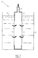
- FIG. 7 shows a schematic cross-sectional view of a fourth embodiment 30 of a device according to the invention.
- the device 30 has a housing 31 in which two microsieves 32 are arranged.
- the housing 31 is submerged into the fluid 33 to be filtered.
- a sufficient under pressure is arranged on the outlet opening 34, which has the result that the fluid to be filtered permeates through the microsieves 32. Any irregularities, which are stopped by the microsieves 32 will fall off the microsieves to the bottom of the container 35 as soon as the microsieves 32 are vibrated.
Abstract
- a feed channel (3) for passing a fluid;
- a permeate outlet channel (5) branching off the feed channel; and
- a filter (6) arranged in the permeate outlet channel for filtering the fluid,
wherein
- the filter is flexible and
- the device comprises vibrating means for vibrating the flexible filter.
Description
- The invention relates to a device for filtering a fluid, which device comprises:
- a feed channel for passing a fluid;
- a permeate outlet channel branching off the feed channel; and
- a filter arranged in the permeate outlet channel for filtering the fluid.
- Such devices are generally known and are used for filtering fluids such as milk, beer, blood or water. With this filtering technique bacteria can be filtered out from the fluid providing a liquid without any harmful constituents, which could impair the storage life of the liquid. For example with milk, sterilization was used to increase the shelf life. However this sterilization discreases the taste of the milk, which makes sterilized milk a less attractive product. Now with this technique of using filters it is possible to maintain the taste of the milk and increase the shelf life thereof.
- A filter specifically suitable for filtration of fluids is for example known from
NL-A-1024292 - The disadvantage of clogging of the filter element is solved by providing a back flow: part of the already filtered fluid is pumped back through the filter elements into the feed flow. This is also often called flow reversal. This results in a decrease in the efficiency of the filter element, because part of the already filtered fluid is lost in the mainstream. It does however solve the clogging of the filter element, as the back flow of fluids carries along the constituents, which clog up the filter.
- The other drawback of the known device, the high costs of the filter can be alleviated to use a polymer filter element, as described by
WO-A-02/43937 - It is now an object of the invention to provide a device, which alleviates most or all of the above-mentioned disadvantages.
- This object is achieved by a device according to the invention, which is characterized in that the filter is flexible and the device comprises vibrating means for vibrating the flexible filter.
- It turns out that only vibrating of the flexible filter is sufficient to prevent clogging up of the filter. It is suspected that by vibrating the filter, the constituents are kept flowing above the filter, such that they can be dragged along with the main flow in the feed channel. Due to the vibrating of the filter, the filter will at least maintain its permeability for a substantial longer time than with the prior art.
- Preferably the filter is a microsieve. In particular these type of applications vibrating of the filter provides a robust filter device, which can filter large quantities of fluid without substantial decrease of the permeability. This does however not exclude the use of other filters for the device according to the invention.
- Preferably the microsieve has pores smaller than 10 micron. The filter could be made from a polymer, like for example explained in
WO-A-02/43937 - In an embodiment of the device according to the invention the vibrating means comprise an actuator attached to the flexible filter. This actuator will move the filter element, such that it will be vibrated and causes removal of any constituents, which could clog up the filter. The actuator can for example be a piezo-electric element. This could fairly easily cause the filter to vibrate.
- In another preferred embodiment of the device according to the invention, the vibrating means comprise pump means for providing a counter flow in the permeate outlet channel, in order to vibrate the flexible filter. By providing a counter flow in the permeate outlet channel, a pressure is build up, which will push back the filter element causing it to move to a other position by removing the counter flow, the original flow in the permeate outlet channel will be re-established bringing the filter back into its original position. It is also possible to provide a volume displacement in the permeate channel, which results in movement of the filter towards the other position. If the pump means provide a pulsated counter flow or pressure, the filter element will be cleaned at a regular interval. It is with a counter flow not necessary and even unwanted to have back flush. It is only necessary to provide with the counter flow a movement of the filter. It is not necessary that fluid, which is already filtered, is pushed back through the filter into the recirculation flow.
- Another option to vibrate the filter is to pass air bubbles through the feed channel. These air bubbles will provide pressure fluctuations, which cause the filter to move.
- The invention further relates to a method for filtering a fluid, which method comprises the steps of:
- passing a fluid along a flexible filter surface, such that part of the fluid flows through the flexible filter into a permeate outlet channel;
- moving at least part of the flexible filter between two outer positions in order to remove any deposition on the filter surface.
- By moving the flexible filter the fluid in the feed channel, which is situated above the flexible filter, will be pushed back by the movement of the filter such that any constituents present in the fluid can be taken along with the feed flow. Also constituents already present on the surface of the filter will be pushed away and again be flowting in the recirculation flow.
- In a preferred embodiment the flexible filter is moved between a convex position and a flat or concave position. This can be obtained by keeping the filter secured on all sides and providing a force onto the surface of the filter. This will make the filter to become convex or concave.
- In yet another preferred embodiment of the method according to the invention, the method comprises the step of providing a counter flow in the permeate outlet channel to move the flexible filter between the outer positions. Preferably the counter flow is controlled such that substantially no flow reversal of the flexible filter occurs. It will only result in a vibrating of the filter causing it to be kept substantially clean.
- It is furthermore preferred if the counter flow is pulsed. A pulsated counter flow will not much influence the flow in the permeate outlet channel, which has advantages for further processing the permeate flow.
- These and other advantages of the invention will be further elucidated in conjunction with the accompanying drawings.
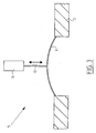
- Figure 1 shows an embodiment of a device according to the invention.
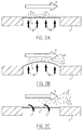
- Figure 2A-2C show cross-sectional views in which the filter is vibrated.
- Figure 3 shows a schematic cross-sectional view of a second embodiment of the device according to the invention.
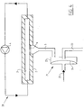
- Figure 4 shows a schematic cross-sectional view of a third embodiment of a device according to the invention.
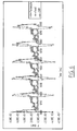
- Figure 5 shows a diagram with measurements of a filtering device according to the prior art.
- Figure 6 shows a diagram of measurements for a device according to the invention.
- Figure 7 shows a schematic cross-sectional view of a fourth embodiment of a device according to the invention.
- Figure 1 shows in partly cross-sectional view and partly schematic view a filtering device 1 according to the invention. The device 1 has a
housing 2, which constitutes afeed channel 3. Fluid is pumped by pump 4 through thisfeed channel 3. In the wall of thechamber 2 an opening is provided, which connects to apermeate outlet channel 5, branching of therecirculation channel 3. In the opening amicrosieve 6 is arranged. When fluid is recirculated by pump 4 part of the fluids flows through thefilter 6 and is designated as permeate 7. The remainingflow 8 of the fluid is pumped out of thehousing 2 and recirculated again over thefilter 6. - In figures 2A-2C the fibrating of the
filter 6 is explained. - In
use constituents 9 tend to clog up thefilter 6 as permeate flows through thefilter 6 and theconstituents 9 are kept behind. In order to keep thefilter 6 clean a counter pressure orforce 10 is provided on the filter 6 (figure 2A). Due to thisforce 10 theflexible filter 6 moves up and gets a convex shape. By this movement of thefilter 6, theconstituents 9 are also moved up into the recirculation flow 8 (see figure 2B). - Now when the
pressure force 10 is removed thefilter element 6 will get back to its original position, amongst others by the permeate flow 7. Theconstituents 9, which were lifted up by thefilter 6 remain flowing in therecirculation flow 8 and will be carried along with thisrecirculation flow 8 and leaving thefilter 6 clean. - Figure 3 shows a second embodiment of a
device 15 according to the invention. This device has a number of features in common with the device 1. Again an opening is provided in thehousing 2 in which afilter 6 is arranged. In order to be able to move thefilter 6 between two positions anactuator 16 is provided, which is attached by arod 17 to the surface of thefilter 6. By hisactuator 16 thefilter 6 can be actively displaced in order to have the constituents flowing above thefilter 6 and have them carried along by the recirculation current. - Figure 4 shows a third embodiment of a
device 20 according to the invention. Also this device has a number of features in common with the device 1 according to the invention. In this embodiment a pulsatingdevice 21 is arranged in thepermeate outlet channel 5. This pulsating device has a housing 22 in which thepermeate outlet channel 5 discharges and a dischargedchannel 23. In the housing a fluidtight membrane 24 is arranged, which can be operated by apressurized airflow 25. This device is described in for exampleNL-A-1024292 permeate outlet channel 5. In order to achieve thispressurized air 25 is arranged on themembrane 24, which will first close off thedischarge channel 23 such that the remaining pressure will result in a counter flow in thepermeate outlet channel 5. - Experiments have been performed in order to determine wether only the movement of the filter already results in the advantages of the invention. The experiments were performed with a device similar according to figure 4 and in which first a silicium nitrate filter was arranged and afterwards a flexible polymer filter. The silicium nitrate filter is a rigid filter, which cannot be flexed and which will not vibrate. The filter used in the experiments had pores of 2 micron. A counter flow was arranged in the
permeate outlet channel 5 of the device according to figure 4. The pulses of this counter flow had a with of 20 m/s and a frequency of 3.3 Hz. The results of the measurements are shown in figure 5. The pressure just above thefilter 6 in therecirculation channel 3 is shown by square measuring points. It is clear that the pressure remains constant and is not influenced by the counter flow in thepermeate outlet channel 5. The pressure in the permeate outlet channel is depicted by diamond shaped measuring points. From figure 5 it is clear that at a regular interval pulses are arranged in the permeate outlet channel. As the pressure difference between the permeate flow and the recirculation flow is inverse during a pulse it is clear that at least some flow reversal will occur in which already filtered fluid will be pushed back through thefilter 6. With this device it was observed that after some time (please insert some data) the permeability of the filter was still decreased to about (to be filled in) %. - The second experiment was performed with a flexible polymer microsieve having pores of 2 micron. The pulse width and frequency of the counter flow in the permeate outlet channel was kept the same.
- From figure 6 it is clear that the pressure in the permeate outlet channel (depicted by round measuring points) is followed by the pressure in the recirculation (depicted by square measuring points). There is no substantial pressure difference between both flows, so no substantial flow reversal will occur with a flexible polymer microsieve. The slight shift in measurements are the result of the inertia of the fluid. With the flexible polymer microsieve it was observed that still after (to be filled in) the permeability of the filter was still above the (to be filled in) %.
- Thus, it can be concluded that only by moving the flexible filter up and down a substantial reduction of constituents clogging up the filter is achieved. The further advantage is that no flow reversal will occur such that the efficiency of this device with the flexible microsieve is increased in comparison to a filter device according to the
- Figure 7 shows a schematic cross-sectional view of a
fourth embodiment 30 of a device according to the invention. Thedevice 30 has ahousing 31 in which twomicrosieves 32 are arranged. Thehousing 31 is submerged into the fluid 33 to be filtered. A sufficient under pressure is arranged on theoutlet opening 34, which has the result that the fluid to be filtered permeates through themicrosieves 32. Any irregularities, which are stopped by themicrosieves 32 will fall off the microsieves to the bottom of thecontainer 35 as soon as themicrosieves 32 are vibrated.
Claims (13)
- Device for filtering a fluid, which device comprises:- a feed channel for passing a fluid;- a permeate outlet channel branching off the feed channel; and- a filter arranged in the permeate outlet channel for filtering the fluid,characterized in that- the filter is flexible and- the device comprises vibrating means for vibrating the flexible filter.
- Device according to claim 1, wherein the filter is a microsieve.
- Device according to claim 2, wherein the microsieve has pores smaller than 10 micron.
- Device according to claim 2 or 3, wherein the filter is made from a polymer.
- Device according to any of the preceding claims, wherein the vibrating means comprise an actuator attached to the flexible filter.
- Device according to claim 5, wherein the actuator is a piezo-electric element.
- Device according to any of the preceding claims, wherein the vibrating means comprise pump means for providing a counter flow in the permeate outlet channel, in order to vibrate the flexible filter.
- Device according to claim 7, wherein the pump means provide a pulsated counter flow.
- Method for filtering a fluid, which method comprises the steps of:- passing a fluid along a flexible filter surface, such that part of the fluid flows through the flexible filter into a permeate outlet channel;- moving at least part of the flexible filter between two outer positions in order to remove any deposition on the filter surface.
- Method according to claim 9, wherein the flexible filter is moved between a convex position and a flat or concave position.
- Method according to claim 9 or 10, comprising the step of providing a counter flow in the permeate outlet channel to move the flexible filter between the two outer positions.
- Method according to claim 11, wherein the counter flow is controlled such that substantially no back flush of the flexible filter occurs.
- Method according to claim 11 or 12, wherein the counter flow is pulsed.
Priority Applications (2)
| Application Number | Priority Date | Filing Date | Title |
|---|---|---|---|
| EP05077172A EP1767258A1 (en) | 2005-09-22 | 2005-09-22 | Filter with vibrating filter element |
| PCT/EP2006/008522 WO2007039030A1 (en) | 2005-09-22 | 2006-08-30 | Filter with vibrating filter element |
Applications Claiming Priority (1)
| Application Number | Priority Date | Filing Date | Title |
|---|---|---|---|
| EP05077172A EP1767258A1 (en) | 2005-09-22 | 2005-09-22 | Filter with vibrating filter element |
Publications (1)
| Publication Number | Publication Date |
|---|---|
| EP1767258A1 true EP1767258A1 (en) | 2007-03-28 |
Family
ID=35613636
Family Applications (1)
| Application Number | Title | Priority Date | Filing Date |
|---|---|---|---|
| EP05077172A Withdrawn EP1767258A1 (en) | 2005-09-22 | 2005-09-22 | Filter with vibrating filter element |
Country Status (2)
| Country | Link |
|---|---|
| EP (1) | EP1767258A1 (en) |
| WO (1) | WO2007039030A1 (en) |
Cited By (3)
| Publication number | Priority date | Publication date | Assignee | Title |
|---|---|---|---|---|
| EP1920814A1 (en) * | 2006-09-19 | 2008-05-14 | Westfalia Separator GmbH | Device for filtering liquids and method for cleaning thereof |
| CN102527132A (en) * | 2010-11-19 | 2012-07-04 | 精工爱普生株式会社 | Fine particle separator |
| US20150190754A1 (en) * | 2014-01-06 | 2015-07-09 | W. L. Gore & Associates, Inc. | Autogenous Cleaning Filtration Method and Device |
Families Citing this family (1)
| Publication number | Priority date | Publication date | Assignee | Title |
|---|---|---|---|---|
| CN114797249B (en) * | 2022-06-08 | 2023-02-07 | 大连理工大学 | Suspension material is collected with seesaw formula feed arrangement |
Citations (6)
| Publication number | Priority date | Publication date | Assignee | Title |
|---|---|---|---|---|
| BE475902A (en) * | ||||
| DE3811706A1 (en) * | 1988-04-08 | 1989-10-19 | Reson System Aps | METHOD FOR CLEANING FILTERS AND APPARATUS FOR EXERCISING THE METHOD |
| DE4404808C1 (en) * | 1994-02-16 | 1995-06-29 | Tuchenhagen Otto Gmbh | Transverse-flow micro-filtration surface assembly movable sepn. wall formed as tube |
| US5769539A (en) * | 1995-08-07 | 1998-06-23 | Phase Technology | Backflush system for a filter membrane located upstream of a hydrocarbon analyzer apparatus |
| DE20119909U1 (en) * | 2001-12-10 | 2002-08-08 | Lauth Werner | Filter element for liquids with blocking protection |
| WO2004078308A1 (en) * | 2003-02-07 | 2004-09-16 | Touzova, Tamara | Vibration method of separating a fluid mixture into a carrier fluid and a complementary component |
-
2005
- 2005-09-22 EP EP05077172A patent/EP1767258A1/en not_active Withdrawn
-
2006
- 2006-08-30 WO PCT/EP2006/008522 patent/WO2007039030A1/en active Application Filing
Patent Citations (6)
| Publication number | Priority date | Publication date | Assignee | Title |
|---|---|---|---|---|
| BE475902A (en) * | ||||
| DE3811706A1 (en) * | 1988-04-08 | 1989-10-19 | Reson System Aps | METHOD FOR CLEANING FILTERS AND APPARATUS FOR EXERCISING THE METHOD |
| DE4404808C1 (en) * | 1994-02-16 | 1995-06-29 | Tuchenhagen Otto Gmbh | Transverse-flow micro-filtration surface assembly movable sepn. wall formed as tube |
| US5769539A (en) * | 1995-08-07 | 1998-06-23 | Phase Technology | Backflush system for a filter membrane located upstream of a hydrocarbon analyzer apparatus |
| DE20119909U1 (en) * | 2001-12-10 | 2002-08-08 | Lauth Werner | Filter element for liquids with blocking protection |
| WO2004078308A1 (en) * | 2003-02-07 | 2004-09-16 | Touzova, Tamara | Vibration method of separating a fluid mixture into a carrier fluid and a complementary component |
Cited By (7)
| Publication number | Priority date | Publication date | Assignee | Title |
|---|---|---|---|---|
| EP1920814A1 (en) * | 2006-09-19 | 2008-05-14 | Westfalia Separator GmbH | Device for filtering liquids and method for cleaning thereof |
| CN102527132A (en) * | 2010-11-19 | 2012-07-04 | 精工爱普生株式会社 | Fine particle separator |
| US20150190754A1 (en) * | 2014-01-06 | 2015-07-09 | W. L. Gore & Associates, Inc. | Autogenous Cleaning Filtration Method and Device |
| CN106061590A (en) * | 2014-01-06 | 2016-10-26 | W.L.戈尔及同仁股份有限公司 | Autogenous cleaning filtration method and device with a flexible filter medium |
| JP2017502840A (en) * | 2014-01-06 | 2017-01-26 | ダブリュ.エル.ゴア アンド アソシエイツ,インコーポレイティドW.L. Gore & Associates, Incorporated | Self-cleaning filtration method and device with flexible filter media |
| CN106061590B (en) * | 2014-01-06 | 2019-07-12 | W.L.戈尔及同仁股份有限公司 | Automatically cleaning filter method and automatically cleaning filter device with elastic filter medium |
| US10369524B2 (en) * | 2014-01-06 | 2019-08-06 | W. L. Gore & Associates, Inc. | Autogenous cleaning filtration method and device |
Also Published As
| Publication number | Publication date |
|---|---|
| WO2007039030A1 (en) | 2007-04-12 |
Similar Documents
| Publication | Publication Date | Title |
|---|---|---|
| JP6648035B2 (en) | Flow control structure and method for fluid filtration device | |
| US9895635B2 (en) | Fluid filtration and particle concentration device and methods | |
| WO2017083438A1 (en) | Solids sensing technology | |
| KR20170021763A (en) | Filtration device and filter element | |
| EP1767258A1 (en) | Filter with vibrating filter element | |
| ES2955330T3 (en) | Filtration and emulsification device | |
| JP2013091046A (en) | Filtration apparatus | |
| JP2012115747A (en) | Hollow fiber membrane module, and hollow fiber membrane module filter | |
| EP1718397B1 (en) | Apparatus and method for micro or ultrafiltration | |
| AU2019379235B2 (en) | Filtering apparatus and method | |
| US20170259212A1 (en) | Cyclic Filtration System | |
| US6579447B2 (en) | Self-cleaning pre-filter system | |
| JP2017006876A (en) | Filter device and filter cleaning method of filter device | |
| JP6653154B2 (en) | Cleaning method and filtration device for hollow fiber membrane module | |
| JP2014018741A (en) | Upward filtration apparatus equipped with fine particle filter medium | |
| CN112584916A (en) | System for filtering and associated method | |
| WO2014006154A1 (en) | Improved filtration unit having a pressure voume adjusting body | |
| WO2014006153A1 (en) | Improved control of permeate flow in a filter | |
| JP2006088017A (en) | Water treatment apparatus and its operating method |
Legal Events
| Date | Code | Title | Description |
|---|---|---|---|
| PUAI | Public reference made under article 153(3) epc to a published international application that has entered the european phase |
Free format text: ORIGINAL CODE: 0009012 |
|
| AK | Designated contracting states |
Kind code of ref document: A1 Designated state(s): AT BE BG CH CY CZ DE DK EE ES FI FR GB GR HU IE IS IT LI LT LU LV MC NL PL PT RO SE SI SK TR |
|
| AX | Request for extension of the european patent |
Extension state: AL BA HR MK YU |
|
| 17P | Request for examination filed |
Effective date: 20070917 |
|
| 17Q | First examination report despatched |
Effective date: 20071030 |
|
| AKX | Designation fees paid |
Designated state(s): AT BE BG CH CY CZ DE DK EE ES FI FR GB GR HU IE IS IT LI LT LU LV MC NL PL PT RO SE SI SK TR |
|
| STAA | Information on the status of an ep patent application or granted ep patent |
Free format text: STATUS: THE APPLICATION IS DEEMED TO BE WITHDRAWN |
|
| 18D | Application deemed to be withdrawn |
Effective date: 20080510 |