EP1590059B1 - Vibrationsverfahren zur trennung einer mischung in eine trägerflüssigkeit und einen komplementären bestandteil - Google Patents
Vibrationsverfahren zur trennung einer mischung in eine trägerflüssigkeit und einen komplementären bestandteil Download PDFInfo
- Publication number
- EP1590059B1 EP1590059B1 EP03717387A EP03717387A EP1590059B1 EP 1590059 B1 EP1590059 B1 EP 1590059B1 EP 03717387 A EP03717387 A EP 03717387A EP 03717387 A EP03717387 A EP 03717387A EP 1590059 B1 EP1590059 B1 EP 1590059B1
- Authority
- EP
- European Patent Office
- Prior art keywords
- chamber
- fluid mixture
- fluid
- separation
- carrier fluid
- Prior art date
- Legal status (The legal status is an assumption and is not a legal conclusion. Google has not performed a legal analysis and makes no representation as to the accuracy of the status listed.)
- Expired - Lifetime
Links
- 239000012530 fluid Substances 0.000 title claims abstract description 125
- 239000000203 mixture Substances 0.000 title claims abstract description 79
- 230000000295 complement effect Effects 0.000 title claims abstract description 50
- 238000000034 method Methods 0.000 title claims abstract description 31
- 230000000737 periodic effect Effects 0.000 claims abstract description 74
- 238000000926 separation method Methods 0.000 claims abstract description 73
- 230000009471 action Effects 0.000 claims abstract description 43
- 238000009434 installation Methods 0.000 claims abstract description 19
- XLYOFNOQVPJJNP-UHFFFAOYSA-N water Substances O XLYOFNOQVPJJNP-UHFFFAOYSA-N 0.000 claims description 45
- 230000001105 regulatory effect Effects 0.000 claims description 22
- 150000003839 salts Chemical class 0.000 claims description 17
- 238000009833 condensation Methods 0.000 claims description 15
- 230000005494 condensation Effects 0.000 claims description 15
- 239000013535 sea water Substances 0.000 claims description 15
- 230000008014 freezing Effects 0.000 claims description 14
- 238000007710 freezing Methods 0.000 claims description 14
- 238000001816 cooling Methods 0.000 claims description 11
- 230000003068 static effect Effects 0.000 claims description 10
- 239000012528 membrane Substances 0.000 claims description 8
- 239000002245 particle Substances 0.000 claims description 8
- 239000000443 aerosol Substances 0.000 claims description 3
- 230000004907 flux Effects 0.000 claims description 2
- 239000013505 freshwater Substances 0.000 claims description 2
- 238000010298 pulverizing process Methods 0.000 claims 2
- 230000001939 inductive effect Effects 0.000 claims 1
- 239000000470 constituent Substances 0.000 description 21
- 238000005507 spraying Methods 0.000 description 20
- 239000007788 liquid Substances 0.000 description 14
- 230000008569 process Effects 0.000 description 10
- 239000006185 dispersion Substances 0.000 description 8
- 239000011148 porous material Substances 0.000 description 8
- 230000005855 radiation Effects 0.000 description 7
- 239000007787 solid Substances 0.000 description 7
- 238000007599 discharging Methods 0.000 description 5
- 229940082150 encore Drugs 0.000 description 5
- 239000007789 gas Substances 0.000 description 5
- 238000010612 desalination reaction Methods 0.000 description 4
- 238000001914 filtration Methods 0.000 description 4
- 238000002156 mixing Methods 0.000 description 4
- 238000000746 purification Methods 0.000 description 4
- 238000004140 cleaning Methods 0.000 description 3
- 238000010586 diagram Methods 0.000 description 3
- 238000006073 displacement reaction Methods 0.000 description 3
- 230000005284 excitation Effects 0.000 description 3
- 230000002349 favourable effect Effects 0.000 description 3
- 238000005374 membrane filtration Methods 0.000 description 3
- 238000001728 nano-filtration Methods 0.000 description 3
- 239000000126 substance Substances 0.000 description 3
- 241000196324 Embryophyta Species 0.000 description 2
- 241000269400 Sirenidae Species 0.000 description 2
- 238000010276 construction Methods 0.000 description 2
- 230000001066 destructive effect Effects 0.000 description 2
- 238000004821 distillation Methods 0.000 description 2
- 239000000839 emulsion Substances 0.000 description 2
- 238000001704 evaporation Methods 0.000 description 2
- 230000008020 evaporation Effects 0.000 description 2
- 239000007792 gaseous phase Substances 0.000 description 2
- 230000003993 interaction Effects 0.000 description 2
- 239000007791 liquid phase Substances 0.000 description 2
- 238000007885 magnetic separation Methods 0.000 description 2
- 239000000463 material Substances 0.000 description 2
- 238000001471 micro-filtration Methods 0.000 description 2
- 230000035515 penetration Effects 0.000 description 2
- 230000002441 reversible effect Effects 0.000 description 2
- 239000007921 spray Substances 0.000 description 2
- 208000003643 Callosities Diseases 0.000 description 1
- 206010020649 Hyperkeratosis Diseases 0.000 description 1
- FAPWRFPIFSIZLT-UHFFFAOYSA-M Sodium chloride Chemical compound [Na+].[Cl-] FAPWRFPIFSIZLT-UHFFFAOYSA-M 0.000 description 1
- 240000008042 Zea mays Species 0.000 description 1
- 235000005824 Zea mays ssp. parviglumis Nutrition 0.000 description 1
- 235000002017 Zea mays subsp mays Nutrition 0.000 description 1
- 230000001143 conditioned effect Effects 0.000 description 1
- 230000001276 controlling effect Effects 0.000 description 1
- 235000005822 corn Nutrition 0.000 description 1
- 239000013078 crystal Substances 0.000 description 1
- 230000008021 deposition Effects 0.000 description 1
- 230000005672 electromagnetic field Effects 0.000 description 1
- 238000005516 engineering process Methods 0.000 description 1
- 238000000605 extraction Methods 0.000 description 1
- 238000011049 filling Methods 0.000 description 1
- -1 gaseous Substances 0.000 description 1
- 238000010438 heat treatment Methods 0.000 description 1
- 238000002347 injection Methods 0.000 description 1
- 239000007924 injection Substances 0.000 description 1
- 230000008018 melting Effects 0.000 description 1
- 238000002844 melting Methods 0.000 description 1
- 239000011859 microparticle Substances 0.000 description 1
- 230000004048 modification Effects 0.000 description 1
- 238000012986 modification Methods 0.000 description 1
- 230000003204 osmotic effect Effects 0.000 description 1
- 239000012071 phase Substances 0.000 description 1
- 238000005293 physical law Methods 0.000 description 1
- 230000000750 progressive effect Effects 0.000 description 1
- 239000008213 purified water Substances 0.000 description 1
- 230000009467 reduction Effects 0.000 description 1
- 239000003507 refrigerant Substances 0.000 description 1
- 230000008929 regeneration Effects 0.000 description 1
- 238000011069 regeneration method Methods 0.000 description 1
- 238000001223 reverse osmosis Methods 0.000 description 1
- 239000011780 sodium chloride Substances 0.000 description 1
- 238000002604 ultrasonography Methods 0.000 description 1
- 238000010792 warming Methods 0.000 description 1
Images
Classifications
-
- B—PERFORMING OPERATIONS; TRANSPORTING
- B01—PHYSICAL OR CHEMICAL PROCESSES OR APPARATUS IN GENERAL
- B01D—SEPARATION
- B01D5/00—Condensation of vapours; Recovering volatile solvents by condensation
- B01D5/0033—Other features
-
- B—PERFORMING OPERATIONS; TRANSPORTING
- B01—PHYSICAL OR CHEMICAL PROCESSES OR APPARATUS IN GENERAL
- B01D—SEPARATION
- B01D1/00—Evaporating
- B01D1/0011—Heating features
-
- B—PERFORMING OPERATIONS; TRANSPORTING
- B01—PHYSICAL OR CHEMICAL PROCESSES OR APPARATUS IN GENERAL
- B01D—SEPARATION
- B01D19/00—Degasification of liquids
- B01D19/0073—Degasification of liquids by a method not covered by groups B01D19/0005 - B01D19/0042
- B01D19/0078—Degasification of liquids by a method not covered by groups B01D19/0005 - B01D19/0042 by vibration
-
- B—PERFORMING OPERATIONS; TRANSPORTING
- B01—PHYSICAL OR CHEMICAL PROCESSES OR APPARATUS IN GENERAL
- B01D—SEPARATION
- B01D29/00—Filters with filtering elements stationary during filtration, e.g. pressure or suction filters, not covered by groups B01D24/00 - B01D27/00; Filtering elements therefor
- B01D29/62—Regenerating the filter material in the filter
- B01D29/70—Regenerating the filter material in the filter by forces created by movement of the filter element
- B01D29/72—Regenerating the filter material in the filter by forces created by movement of the filter element involving vibrations
-
- B—PERFORMING OPERATIONS; TRANSPORTING
- B01—PHYSICAL OR CHEMICAL PROCESSES OR APPARATUS IN GENERAL
- B01D—SEPARATION
- B01D5/00—Condensation of vapours; Recovering volatile solvents by condensation
- B01D5/0033—Other features
- B01D5/0042—Thermo-electric condensing; using Peltier-effect
Definitions
- the invention relates to the separation of a fluid mixture into a carrier fluid and a complementary component.
- the fluid mixtures correspond to very diverse physical media comprising several constituents.
- These fluid mixtures may be homogeneous, that is to say consist of a single liquid or gaseous phase, or heterogeneous, that is to say consist of at least one liquid or gaseous phase and at least one second phase liquid, gaseous, solid or colloidal.
- a carrier fluid For many applications, it is sought to separate the constituents of a fluid mixture on the one hand a carrier fluid and on the other hand a complementary component.
- various methods are used such as membrane filtration, nano and microfiltration, reverse osmosis, liquid membrane emulsion and combinations thereof, as well as mechanical, ultrasonic, electrical, magnetic separation processes. and mixed (for example electromagnetic) or distillation processes.
- the object of the present invention is to overcome these disadvantages by providing a means for purifying a physical medium having improved performance and requiring significantly reduced time and energy expenditure.
- the subject of the invention is a process for separating a fluid mixture into a carrier fluid and a complementary constituent by means of a separation device consisting of a fluid mixture inlet device, a a separation chamber comprising a first chamber, a second chamber and a separation means, a carrier fluid evacuation device and a device for discharging the complementary constituent, according to which a flow of fluid mixture is sent.
- a separation device consisting of a fluid mixture inlet device, a a separation chamber comprising a first chamber, a second chamber and a separation means, a carrier fluid evacuation device and a device for discharging the complementary constituent, according to which a flow of fluid mixture is sent.
- the fluid mixture inlet device so as to introduce it into the first chamber
- the separation means the fluid mixture is separated into a carrier fluid which is collected in the second chamber and a complementary component which remains in the first chamber, and the carrier fluid is evacuated by the evacuation device of the carrier fluid and the complementary constituent by the evacuation device of the complementary constituent. to hush up.
- the fluid mixing stream is subjected to the action of at least a first periodic phenomenon having a first frequency
- the mixture in the first chamber, the mixture is subjected to fluid to the action of at least one second periodic phenomenon having a second frequency, the frequencies of the first periodic phenomenon and the second periodic phenomenon being in a ratio greater than 10, and the flow rate of arrival of the fluid mixture is controlled, the discharge rate of the carrier fluid and the discharge rate of the complementary constituent.
- the periodic phenomena used may be of different type, and in particular of the mechanical, acoustic, ultrasonic, thermal, electrical, magnetic or mixed type for example electromagnetic, electromechanical etc.
- At least one third periodic phenomenon can be subjected to at least one of the separation means.
- the different periodic phenomena used are regulated in frequency and / or in amplitude as a function of at least one of the fluid mixture, carrier fluid and complementary constituent flow rates.
- the separation means may comprise at least one membrane.
- the fluid mixture When introducing the fluid mixture into the first chamber, it is also possible to finely spray or micronize said fluid mixture so as to produce a medium consisting of particles whose dimensions are smaller than one micron, and, with the aid of periodic phenomena, said particles are condensed, and the carrier fluid and the complementary constituent are separated.
- the fluid mixture can be subjected to the action of a periodic phenomenon of the microwave or ultrasound type, or their combination.
- waves of carrier fluid flow can be created by means of at least one periodic action formed by a condensation device consisting of a baffle. This process is particularly applicable to the desalination of seawater, and in this case the fluid mixture is seawater, the carrier fluid is fresh water and the complementary element is water to high concentration of salt.
- the invention also relates to an installation for implementing the separation method according to the invention.
- This installation comprises a fluid mixture inlet device, a separation chamber, a carrier fluid evacuation device and a device for discharging the complementary component, said separation chamber comprising a first chamber, a second chamber and a means of separation.
- the fluid mixture inlet device comprises at least one device for acting at least a first periodic phenomenon
- at least the first chamber comprises at least one device for causing at least one second periodic phenomenon.
- the device according to the invention also comprises means for controlling and regulating the fluid mixture inlet device, the carrier fluid evacuation device, the complementary constituent evacuation device, and devices for causing the at least first and second periodic phenomena to act.
- At least one device for effecting a periodic phenomenon may be, for example, a whistle or a siren animated by the flow current of the fluid mixture.
- the installation according to the invention may comprise at least one means for causing a periodic electromagnetic and / or thermal phenomenon to act on the fluid mixture inlet stream, at least one means for causing a mechanical or ultrasonic periodic phenomenon to act, a means for spraying method for micronizing and spraying in the form of vapor and / or aerosol the fluid mixture, a means for condensing the fluid mixture into a carrier fluid and a complementary component of the type comprising at least one means such as a static baffle , a dynamic baffle generated by a whistle or a siren, or a means acting by cooling or freezing, and a means for causing a periodic phenomenon of the electromagnetic and / or thermal type to heat the carrier fluid.
- it may comprise means for evacuating the carrier fluid and means for discharging the complementary constituent, consisting of suction pumps and regulating valves, and means for supplying and regulating the means for causing the periodic phenomena to act.
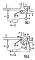
- the installation represented at figure 1 comprises a separation chamber 1 in which a physical medium is separated into a vehicle medium and a medium to be separated, by means of a separation means 3 which divides the chamber 1 into at least two chambers 4 and 6, a first chamber 6 constituting a volume in which the vehicle medium accumulates and a second chamber 4 constituting a volume in which the medium to be separated is concentrated.
- the separation means 3 is for example a filtration membrane or micro filtration, or nano filtration, or an osmotic membrane.
- a fluid mixture inlet device 2 makes it possible to introduce the physical medium into the separation chamber 1 and opens, in general, into the first chamber 6 in which the medium to be separated is concentrated.
- This fluid mixture inlet device 2 consists, for example, of a pipe, a pump and a valve.
- a carrier fluid evacuation device 8 provides regulated evacuation of the current of the vehicle medium.
- This device consists, for example, of a pipe provided with a controlled valve and / or a discharge pump.
- a complementary constituent discharge device 9 ensures a controlled current of the medium to be separated.
- This device consists for example of a pipe and a controlled valve and / or a discharge pump.
- the installation further comprises a device 11 for causing a first periodic phenomenon to act on the physical medium in the fluid mixture inlet device 2; a second device 12 for causing a second vibratory phenomenon to act on the physical medium in the first chamber 6, a third device 13 for causing a third periodic phenomenon to act on the separation means 3.
- a source of supply that can be adjusted by means electronic control device 10a of external periodic action (vibratory), the devices 11, 12 and 13 intended to act periodic phenomena on the physical medium and on the separation means 3.
- the physical medium may consist of a liquid medium, gaseous or mixed, in whose composition can enter liquids, gases, colloidal or solid bodies or combinations thereof.
- the medium to be separated may consist of organic and / or non-organic substances of liquid, gaseous, colloidal and solid type or combinations of such substances.
- the separation system 3 can be formed of at least one device or element for membrane filtration, nanofiltration, reverse osmone, a liquid system and emulsion membrane or combinations of these devices, elements and systems, and also a system of mechanical, ultrasonic, electrical and / or magnetic separation or combination of such systems.
- the arrangement of the system 3 relative to the horizontal (or the base of the device) can be any: horizontal, vertical or at any angle.
- the separation system 3 is in the form of a cylinder, for example, forming a rotating part of a centrifuge, the chamber 6 into which the current of the physical medium is introduced and in which the medium to be separated is then concentrated. is located inside this cylinder, while the chamber 4 for collecting the vehicle medium is located outside this cylinder.
- the devices 11, 12 and 13 for effecting periodic phenomena may be in the form of at least one ultrasonic action device, for example a siren, a whistle, a piezoelectric vibrator or a combination thereof.
- the power supply system 10 provides the necessary operating speeds of the devices 11, 12 and 13 intended to act on periodic phenomena, and comprises the regulator 10a make it possible to vary the frequencies and the amplitudes of energy as a function of the operating regimes. of these devices.
- the systems 10 and 10a can regulate the flow rate of the device by varying the frequency and the amplitude of the periodic actions on the treated media and on the devices for regulating the evacuation of these media.
- a source of energy it is possible to use the streams of the treated medium and of the vehicle medium. This is the case, in particular, when the devices intended to act a periodic phenomenon are whistles or sirens.
- the first and second periodic phenomena acting on the physical medium have frequencies which, preferably, are in a ratio greater than 10. That is to say, that the frequency of the second phenomenon is more than 10 times greater than the frequency of the first phenomenon, or the frequency of the first phenomenon is more than 10 times higher than the frequency of the second phenomenon.
- the devices 11, 12 and 13 for operating periodic phenomena can correspond to one and the same periodic phenomenon.
- the physical medium interacts with the separation system 3 to which a vibratory action is applied, ensuring the conditions of its self-cleaning and its uninterrupted operation in stationary mode; for example, the surface of the separation system 3 is subjected to the action of vortex currents, created by a rotating disk of determined configuration.
- the vehicle medium obtained as a result of the separation and cleaning is discharged from the separation chamber 1 by the carrier fluid evacuation device 8, in a controlled regime.
- the device comprises a separation chamber 21 in which a physical medium is separated into a vehicle medium and a medium to be separated, by means of a separation means 23 which divides the enclosure 21 into at least two chambers 24 and 26, the chamber 24 constituting a volume in which the vehicle medium and the chamber 26 constituting a volume in which the medium to be separated is concentrated.
- the separation means 23 consists of a means of micronization and spraying 23a of the physical medium which is, for example, an injector, and a condensing means 23b.
- a fluid mixing inlet device 22 makes it possible to introduce the physical medium into the separation chamber 21 and opens into the chamber 26 through the micronization and spraying device 23a so that the physical medium enters the chamber.
- the fluid mixture inlet device 22 consists for example of a pipe, a pump and a valve.
- a carrier fluid evacuation device 28 provides controlled evacuation of the vehicle medium current.
- This device consists for example of a pipe provided with a controlled valve and / or a discharge pump.
- a complementary constituent discharge device 29 ensures a regulated current of the medium to be separated.
- This device consists for example of a pipe and a controlled valve and / or a discharge pump.
- the installation further comprises a device 31 for causing a first periodic phenomenon to act on the physical medium in the fluid mixture inlet device 22; a second device 32 for causing a second vibratory phenomenon to act on the physical medium is associated with the micronization and spraying means 23a; a third device 33 for effecting a third periodic phenomenon is associated with the cooling means 23b; finally, a fourth device 34 intended to cause a fourth periodic phenomenon to act in the second chamber 24.
- a source of supply 30 that can be adjusted by means of an electronic control device 30a of external periodic action (vibratory), supplies the devices 31, 32, 33 and 34 for effecting periodic phenomena on the physical medium and on the means 23a and 23b of the separation device 23.
- the micronization and spraying means 23a with a fine dispersion of the physical medium is, for example, a mechanical and / or acoustic sprayer which disperses and injects the physical medium in the form of steam and / or aerosol with Particle size (droplets) of the molecular level (below one micron).
- the condensing means 23b is, for example, a static baffle or a dynamic baffle constituted by a means such as a whistle or a siren generating a pulsating flow of the fluid, or a means of cooling or freezing.
- this means can be a vibratory means as described in the French patent application published under the number FR 28 02118 .
- the separation device 23 is a system consisting on the one hand of an injector 23a and an acoustic micronizer chamber, which sprays the fine-dispersion physical medium and on the other hand a condensing means 23b, the first Chamber 26 is a reservoir in which the medium to be separated is concentrated and the chamber 24 is a reservoir for the carrier or carrier medium.
- Each of the vibratory action systems 31, 32, 33 and 34 may consist of at least one device of mechanical type, for example a mechanical vibrator or an ultrasonic action device, for example a siren, a whistle, a piezoelectric vibrator, or a device creating an electromagnetic or magnetic field or a radiation of corresponding configuration and intensity, or finally different combinations of the devices and systems listed above.
- a mechanical vibrator or an ultrasonic action device for example a siren, a whistle, a piezoelectric vibrator, or a device creating an electromagnetic or magnetic field or a radiation of corresponding configuration and intensity, or finally different combinations of the devices and systems listed above.
- the power supply system 30 provides the essential operating regimes of the vibratory systems 31, 32, 33 and 34 and comprises the regulator 30a make it possible to vary the frequencies and the amplitudes of energy as a function of the operating speeds of these vibratory systems. In this way, the systems 30 and 30a can regulate the flow rate of the device by varying the frequency and the amplitude of the periodic actions on the treated media and on the regulating devices. Evacuation of these media As a source of energy, it is possible to use the currents of the physical medium and the vehicle medium.
- the physical medium may consist of a liquid, gaseous or mixture medium, into which liquid, gas, colloidal and solid bodies or combinations thereof may enter.
- the medium to be separated (elements and bodies to be separated) may consist of organic and / or non-organic bodies of liquid, gaseous, colloidal or solid type or of their combination.
- the regulated current of the physical medium arriving via the fluid mixture inlet device 22 is admitted into the micronization and spraying means 23a; during its displacement, the current of the physical medium is subjected to at least one vibratory action 31 immediately before its penetration into the micronization and spraying means 23a, for example by means of microwave radiation, which creates a complementary condition favorable to the treatment of the physical medium in the micronization and spraying means 23a; then, the physical medium is micronized and pulverized by the micronization and spraying means 23a by means of the corresponding periodic action 32.
- Actions 31 and 32 above establish the necessary and sufficient conditions for spraying the fine-dispersion physical medium in the form of microparticle vapor and prepare it for the rapid cooling and / or freezing process in the refrigerating medium 23b .
- the fine dispersed particles of cooled and / or frozen vehicle medium enter the chamber 24 in which they melt under the action of a periodic radiation 34, for example a microwave or a other thermal radiation and are discharged using the carrier fluid discharge device 28 in a controlled regime.
- a periodic radiation 34 for example a microwave or a other thermal radiation
- the particles of the medium to be separated for example water with a high concentration of salt, whose freezing temperature differs considerably from the freezing temperature of the vehicle medium, are concentrated in the chamber 26 and are discharged out of the system by the complementary constituent evacuation device in the regulated regime.
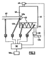
- FIG 3 is represented the diagram of an installation implementing a process of desalination of seawater by the separation of salt water (physical medium or fluid mixture) in a vehicle medium (purified water) and a medium to be separated ( water with a very high concentration of salt), using at least one separation means, according to the invention.
- salt water physical medium or fluid mixture
- vehicle medium purified water
- medium to be separated water with a very high concentration of salt
- the installation represented at figure 3 comprises a separation chamber 41 in which a controlled current of seawater supplied by a fluid mixture inlet device 42 is separated into a vehicle medium and a medium to be separated.
- the separation chamber 41 comprises at least one vibratory separation means 43 for the salted water in carbonated water (vaporized) and salt water having a higher concentration of salt, and at least two chambers 44 and 46 in which penetrate and are treated salt water, the vehicle medium and the medium to be separated respectively.
- the separating means 43 is a vibratory means. It consists of a vibration vibratory device 43a and a vibration vibrating means 43b.
- At least one device for discharging the carrier fluid 48 ensures the translation of the gasified (vaporized) water molecules supplemented by a device 48a ensuring the evacuation of the regulated current from the vehicle medium and the condensation of the gasified water molecules (vaporized) to form a purified liquid medium (pure water).
- At least one evacuation device of the complementary constituent 49 ensures the evacuation of the regulated current from the medium to be separated.
- the vibration vibratory device 43a disposed at the outlet of the fluid mixing inlet device 42 in the chamber 46 vaporizes the seawater which enters the separation chamber.
- the vibratory condensation means 43b disposed between the chambers 44 and 46, makes it possible to separate the vehicle medium (pure water vapor) and the medium to be separated (water very heavily loaded with salt).
- Means for causing a periodic phenomenon to act 53, 54 make it possible to act a periodic phenomenon on the vehicle medium and the medium to be separated.
- the means for operating a periodic phenomenon 51, 52, 53 and 54 are controlled by at least one power source 50 adjustable by electronic adjustment means 50a.
- the regulated stream of seawater inlet can also be naturally or artificially salted water, or else water in the composition of which can enter different liquid components, gases, colloidal bodies or solids or their combinations.
- the carrier medium may consist of gasified water molecules (vaporized), fine droplets of water and pulsed air (repressed).
- the pulsed air may be constituted by elements providing cooling and / or freezing the gasified water molecules (vaporized) obtained by the vibratory treatment 54.
- the medium to be separated may consist of concentrated salt water and salt crystals as well as the composition of which can enter different liquid components, gases, colloidal or solid corns or combinations thereof.
- a device for operating a periodic phenomenon 53 represents a device for cooling and / or freezing pure water molecules. It is a conventional freezing system and / or a refrigerant, easily separable subsequently vehicle medium.
- An evacuation device of the carrier fluid 48 ensures the translation of the gasified water molecules (vaporized). It consists for example of a regulated vacuum fan, and / or at least one suction pneumatic pump, or together. It is completed by a device 48a ensuring the evacuation of the controlled current of the vehicle medium, consisting for example of a controlled valve and / or a centrifugal extraction pump for the condensation of gasified water molecules.
- a complementary component evacuation device 49 ensuring the evacuation of the regulated current of the medium to be separated consists for example of a regulated valve and / or a hydraulic drain pump.
- Each of the devices making it possible to act on periodic phenomena 51, 52, 53 and 54 may consist of at least one device of the mechanical type, for example a hydraulic, pneumatic or mixed pump, or at least one device.
- ultrasonic action for example a siren, a whistle, a piezoelectric vibrator, or at least one device creating an electromagnetic or magnetic field, or a thermal radiation of corresponding configuration and intensity, or finally different combinations of devices and systems mentioned above.
- the feed device 50 provides the necessary operating regimes of the devices for operating periodic phenomena 51, 52, 53 and 54, as well as spraying devices 43a and separation 43b. It further comprises the regulator 50a allow to vary the frequencies and powers (energy expenses) according to the operating regimes of the systems mentioned that it feeds and manages. In this way, the feed device 50 and control device 50a can provide flow control of the device by varying the frequency and amplitude of the vibratory actions on the treated media, as well as the regulation of the working patterns of the evacuation devices carrier fluid 48 and the complementary constituent 49 ensuring the translation and evacuation of these media. As a source of energy, it is also possible to use the streams of the treated medium and the vehicle medium and the medium to be separated, for example to feed the sirens and whistles.
- the regulated current of seawater is admitted into the micronization and spraying device 43a.
- the current of the seawater may be subjected to at least one vibratory action 51, immediately before its penetration into the spraying device 43a, for example by means of thermal radiation (less than 100 ° C), which creates a favorable condition favorable to the treatment of seawater in the spraying device 43a performing its micronization and spraying in the chamber 46.
- gasified water for example cold vapor (less than 100 ° C) and fine droplets of saline water (less than 1 micron) prepared for treatment in separating device 43b.
- the vehicle medium (pure water) obtained by the actions cited is evacuated using the device for discharging the vehicle medium, 48 and 48a, in a controlled regime.
- the droplets of the medium to be separated for example water with a high concentration of salt, whose freezing temperature differs considerably from the freezing temperature of the vehicle medium, are concentrated at the bottom in the chamber 44 and are discharged out of the system by the device for evacuating the complementary constituent 49, in regulated mode.
- condensation device 48a for example in at least one condensation chamber of a centrifugal pump.
- condensation device 48a for example in at least one condensation chamber of a centrifugal pump.
- the use of devices to act periodic phenomena 53 and 54 to ensure freezing and warming is not necessary.
- the present invention uses a method of simultaneous action on a physical medium and / or on a medium to be separated using at least two periodic actions, as described previously in the French patent.
- FR-A-2,744,931 the same applicants.
- the implementation of at least two periodic actions on the treated media is used not for their mixing, but for their separation and concentration.
- a resonant cavitation is produced, which breaks the molecules of the physical medium into constituents, for example into molecules of the carrier medium and of the medium to be separated.
- the molecules of the carrier medium and the medium to be separated are then present in unbound form thanks to their resonant excitation.
Landscapes
- Chemical & Material Sciences (AREA)
- Chemical Kinetics & Catalysis (AREA)
- Physical Or Chemical Processes And Apparatus (AREA)
- Organic Low-Molecular-Weight Compounds And Preparation Thereof (AREA)
- Physical Water Treatments (AREA)
- Extraction Or Liquid Replacement (AREA)
- Treatment Of Liquids With Adsorbents In General (AREA)
- Separation Using Semi-Permeable Membranes (AREA)
- Combined Devices Of Dampers And Springs (AREA)
Claims (10)
- Vibrationsverfahren zum Trennen eines Fluidgemischs in ein Trägerfluid und eine komplementäre Komponente mit Hilfe einer Trennungseinrichtung, die zusammengesetzt ist aus einer Fluidgemisch-Eingangsvorrichtung (2, 22, 42), einem Trennraum (1, 21, 41), der eine erste Kammer (6, 26, 46), eine zweite Kammer (4, 24, 44) und ein Trennungsmittel (3, 23, 43) aufweist, einer Trägerfluid-Ableitungsvorrichtung (8, 28, 48) und einer Vorrichtung zum Ableiten der komplementären Komponente (9, 29, 49), gemäß welchem ein Fluidgemisch-Strom auf eine derartige Weise in die Fluidgemisch-Eingangsvorrichtung (2, 22, 42) zugeführt wird, dass dieser in die erste Kammer (6, 26, 46) eingeführt wird, das Fluidgemisch mit Hilfe des Trennungsmittels in ein Trägerfluid, das in der zweiten Kammer (4, 24, 44) aufgenommen wird, und eine komplementäre Komponente, die in der ersten Kammer (6, 26, 46) bleibt, getrennt wird, und das Trägerfluid durch die Trägerfluid-Ableitungsvorrichtung (8, 28, 48) und die komplementäre Komponente durch die Vorrichtung zum Ableiten der komplementären Komponente (9, 29, 49) abgeleitet werden, dadurch gekennzeichnet, dass der Fluidgemisch-Strom in der Fluidgemisch-Eingangsvorrichtung (2, 22, 42) der Wirkung mindestens eines ersten periodischen Phänomens mit einer ersten Frequenz unterworfen wird, und das Fluidgemisch in der ersten Kammer (6, 26, 46) der Wirkung mindestens eines zweiten periodischen Phänomens mit einer zweiten Frequenz unterworfen wird, wobei die Frequenzen des ersten periodischen Phänomens und des zweiten periodischen Phänomens vorzugsweise ein Verhältnis von größer als 10 haben, und der Eingangsdurchfluss des Fluidgemischs, der Ableitungsdurchfluss des Trägerfluids und der Ableitungsdurchfluss der komplementären Komponente reguliert werden, wobei mindestens eines der verwendeten periodischen Phänomene mechanischer, akustischer, Ultraschall-, thermischer, elektrischer, magnetischer oder elektromagnetischer oder daraus gemischter Art ist.
- Verfahren gemäß Anspruch 1, dadurch gekennzeichnet, dass ferner mindestens das Trennungsmittel (3, 23, 43) der Wirkung mindestens eines dritten periodischen Phänomens unterworfen wird.
- Verfahren gemäß Anspruch 1 oder Anspruch 2, dadurch gekennzeichnet, dass das Trennungsmittel (3) mindestens eine Membran aufweist.
- Verfahren gemäß einem der Ansprüche 1 bis 3, dadurch gekennzeichnet, dass beim Einführen des Fluidgemischs in die erste Kammer (26, 46) das Fluidgemisch fein pulverisiert oder mikronisiert wird, so dass ein Medium erzeugt wird, das aus Teilchen gebildet ist, deren Abmessungen kleiner als ein Mikrometer sind, und dass die Teilchen mit Hilfe von periodischen Phänomenen kondensiert werden, und das Trägerfluid und die komplementäre Komponente voneinander getrennt werden.
- Verfahren gemäß Anspruch 4, dadurch gekennzeichnet, dass das Fluidgemisch, um das Pulverisieren oder Mikronisieren des Fluidgemischs zu erleichtern, der Wirkung eines periodischen Phänomens des Mikrowellen-, Ultraschall- oder Mischtyps unterworfen wird.
- Verfahren gemäß Anspruch 4 oder Anspruch 5, dadurch gekennzeichnet, dass, um das mikronisierte Fluidgemisch in ein Trägerfluid und eine komplementäre Komponente zu trennen, mit Hilfe mindestens einer periodischen Wirkung, die durch eine Kondensierungsvorrichtung (23b, 43b) gebildet von einem statischen und/oder dynamischen Hindernis gebildet wird, Trägerfluidstromwellen erzeugt werden.
- Verfahren gemäß einem der Ansprüche 4 bis 6, dadurch gekennzeichnet, dass das Fluidgemisch Meerwasser ist, das Trägerfluid Süßwasser ist, und die komplementäre Komponente Wasser mit hoher Salzkonzentration ist.
- Einrichtung zum Durchführen des Verfahrens gemäß einem der Ansprüche 1 bis 4, aufweisend eine Fluidgemisch-Eingangsvorrichtung (2, 22, 42), einen Trennraum (1, 21, 41), eine Trägerfluid-Ableitungsvorrichtung (8, 28, 48) und eine Vorrichtung zum Ableiten der komplementären Komponente (9, 29, 49), wobei der Trennraum (1, 21, 41) eine erste Kammer (6, 26, 46), eine zweite Kammer (4, 24, 44) und ein Trennungsmittel (3, 23, 43) aufweist, dadurch gekennzeichnet, dass die Fluidgemisch-Eingangsvorrichtung (2, 22, 42) mindestens eine Vorrichtung aufweist, um mindestens ein erstes periodisches Phänomen (11, 31, 51) wirken zu lassen, dass mindestens die erste Kammer (6, 26, 46) mindestens eine Vorrichtung aufweist, um mindestens ein zweites periodisches Phänomen (12, 32, 52) wirken zu lassen, und dass sie ferner Mittel zum Steuern (10, 30, 50) und zum Regulieren (10a, 30a, 50a) der Fluidgemisch-Eingangsvorrichtung (2, 22, 42), der Trägerfluid-Ableitungsvorrichtung (8, 28, 48), der Vorrichtung zum Ableiten der komplementären Komponente (9, 29, 49) und der Vorrichtungen aufweist, die vorgesehen sind, um das mindestens eine erste und zweite periodische Phänomen (11, 12, 31, 32, 51, 52) wirken zu lassen.
- Einrichtung gemäß Anspruch 8, dadurch gekennzeichnet, dass mindestens eine Vorrichtung zum Wirkenlassen eines periodischen Phänomens (11, 12, 31, 32, 51, 52) eine Pfeife oder eine Sirene ist, die durch den Fluidgemisch-Eingangsstrom angeregt werden.
- Einrichtung zum Durchführen des Verfahrens gemäß einem der Ansprüche 4 bis 6, aufweisend eine Fluidgemisch-Eingangsvorrichtung (22, 42), einen Trennraum (21, 41), eine Trägerfluid-Ableitungsvorrichtung (28, 48) und eine Vorrichtung zum Ableiten der komplementären Komponente (29, 49), wobei der Trennraum (21, 41) eine erste Kammer (26, 46), eine zweite Kammer (24, 44) und ein Trennungsmittel (23, 43) aufweist, dadurch gekennzeichnet, dass sie aufweist: mindestens ein Mittel, um ein elektromagnetisches und/oder thermisches periodisches Phänomen (31, 51) auf den Fluidgemisch-Eingangsstrom wirken zu lassen, mindestens ein Mittel, um ein mechanisches oder Ultraschall- periodisches Phänomen (32, 52) wirken zu lassen, und ein Pulverisierungsmittel (23a, 43a), um das Fluidgemisch in Form von Dampf oder Aerosol zu mikronisieren und zu pulverisieren, dass sie ein Mittel zum Kondensieren (23b, 43b) des Fluidgemischs in ein Trägerfluid und eine komplementäre Komponente aufweist, des Typs, der mindestens ein Mittel aufweist, das ausgewählt ist aus einem statischen Hindernis, einem mittels einer Pfeife oder einer Sirene erzeugten dynamischen Hindernis, oder einem durch Abkühlen oder Einfrieren wirkenden Mittel, dass sie ein Mittel aufweist, um ein periodisches Phänomen (34, 54) des elektromagnetischen und/oder thermischen Typs wirken zu lassen, um das Trägerfluid wieder aufzuwärmen, dass sie Mittel (28, 48), um das Trägerfluid abzuleiten, und Mittel, um die komplementäre Komponente (29, 49) abzuleiten, aufweist, die aus Saugpumpen und Regelventilen gebildet sind, und dass sie Mittel zum Versorgen (30, 50) und Regulieren (30a, 50a) der Mittel zum Wirkenlassen der periodischen Phänomene aufweist.
Applications Claiming Priority (1)
| Application Number | Priority Date | Filing Date | Title |
|---|---|---|---|
| PCT/FR2003/000408 WO2004078308A1 (fr) | 2003-02-07 | 2003-02-07 | Procede vibratoire de separation d'un melange fluide en un fluide porteur et un constituant complementaire |
Publications (2)
| Publication Number | Publication Date |
|---|---|
| EP1590059A1 EP1590059A1 (de) | 2005-11-02 |
| EP1590059B1 true EP1590059B1 (de) | 2011-04-06 |
Family
ID=32947090
Family Applications (1)
| Application Number | Title | Priority Date | Filing Date |
|---|---|---|---|
| EP03717387A Expired - Lifetime EP1590059B1 (de) | 2003-02-07 | 2003-02-07 | Vibrationsverfahren zur trennung einer mischung in eine trägerflüssigkeit und einen komplementären bestandteil |
Country Status (7)
| Country | Link |
|---|---|
| EP (1) | EP1590059B1 (de) |
| CN (1) | CN100398176C (de) |
| AT (1) | ATE504344T1 (de) |
| AU (1) | AU2003222367A1 (de) |
| BR (1) | BR0318044B1 (de) |
| DE (1) | DE60336685D1 (de) |
| WO (1) | WO2004078308A1 (de) |
Families Citing this family (4)
| Publication number | Priority date | Publication date | Assignee | Title |
|---|---|---|---|---|
| EP1767258A1 (de) * | 2005-09-22 | 2007-03-28 | Universiteit Twente | Filter mit schwingendem Filterelement |
| JP2012106208A (ja) * | 2010-11-19 | 2012-06-07 | Seiko Epson Corp | 微粒子分離装置 |
| RU2708046C1 (ru) * | 2018-10-08 | 2019-12-03 | Федеральное государственное бюджетное образовательное учреждение высшего образования "Московский государственный университет имени М.В. Ломоносова" (МГУ) | Способ и устройство для разделения смеси газов по молекулярной массе |
| RU2724101C1 (ru) * | 2019-08-30 | 2020-06-22 | Федеральное государственное бюджетное образовательное учреждение высшего образования "Московский государственный университет имени М.В. Ломоносова" (МГУ) | Способ и устройство для разделения смеси газов по молекулярной массе |
Family Cites Families (7)
| Publication number | Priority date | Publication date | Assignee | Title |
|---|---|---|---|---|
| US2893707A (en) * | 1955-08-29 | 1959-07-07 | Leslie K Gulton | Method of ultrasonic treatment and device |
| US3614069A (en) * | 1969-09-22 | 1971-10-19 | Fibra Sonics | Multiple frequency ultrasonic method and apparatus for improved cavitation, emulsification and mixing |
| AT389235B (de) * | 1987-05-19 | 1989-11-10 | Stuckart Wolfgang | Verfahren zur reinigung von fluessigkeiten mittels ultraschall und vorrichtungen zur durchfuehrung dieses verfahrens |
| FR2744931B1 (fr) * | 1996-02-20 | 1998-08-28 | Danil Doubochinski | Procede et dispositif de preparation d'une emulsion a partir de constituants non miscibles |
| US5733416A (en) * | 1996-02-22 | 1998-03-31 | Entropic Systems, Inc. | Process for water displacement and component recycling |
| FR2802118A1 (fr) * | 1999-12-10 | 2001-06-15 | Touzova Tamara | Procede et dispositif vibratoire de conditionnement, de climatisation, de refroidissement et de decontamination, de desinfection, de sterilisation de milieux physiques |
| US6395186B1 (en) * | 2000-06-20 | 2002-05-28 | Delaware Capital Formation, Inc. | Pressure liquid filtration with ultrasonic bridging prevention |
-
2003
- 2003-02-07 BR BRPI0318044-1A patent/BR0318044B1/pt not_active IP Right Cessation
- 2003-02-07 CN CNB038262533A patent/CN100398176C/zh not_active Expired - Fee Related
- 2003-02-07 AT AT03717387T patent/ATE504344T1/de not_active IP Right Cessation
- 2003-02-07 WO PCT/FR2003/000408 patent/WO2004078308A1/fr not_active Ceased
- 2003-02-07 AU AU2003222367A patent/AU2003222367A1/en not_active Abandoned
- 2003-02-07 EP EP03717387A patent/EP1590059B1/de not_active Expired - Lifetime
- 2003-02-07 DE DE60336685T patent/DE60336685D1/de not_active Expired - Lifetime
Also Published As
| Publication number | Publication date |
|---|---|
| CN1758943A (zh) | 2006-04-12 |
| WO2004078308A1 (fr) | 2004-09-16 |
| EP1590059A1 (de) | 2005-11-02 |
| CN100398176C (zh) | 2008-07-02 |
| ATE504344T1 (de) | 2011-04-15 |
| AU2003222367A1 (en) | 2004-09-28 |
| BR0318044A (pt) | 2005-12-06 |
| BR0318044B1 (pt) | 2013-04-02 |
| DE60336685D1 (de) | 2011-05-19 |
Similar Documents
| Publication | Publication Date | Title |
|---|---|---|
| CA2796117C (en) | Ultrasound and acoustophoresis technology for separation of oil and water, with application to produce water | |
| EP0577713B1 (de) | Zyklon mit Doppelextraktionseffekt | |
| EP2240411B1 (de) | Vorrichtung zur entsalzung von meerwasser durch versprühen bei umgebungstemperatur | |
| EP1044061A1 (de) | Vorrichtung, system und verfahren zur abtrennung von flüssigkeiten | |
| EP2945910B1 (de) | Flüssigkeitsbehandlungsvorrichtung | |
| JP2007307553A (ja) | 噴射流技術を利用する海水淡水化システム | |
| FR2655279A1 (fr) | Procede de micro-pulverisation d'une solution par ultra son et diffuseur de micro-gouttelettes mettant en óoeuvre le dit dispositif. | |
| MX2010009706A (es) | Procesador de cavitacion electrohidraulica y de cizallamiento de liquidos a contraflujo radial. | |
| EP1590059B1 (de) | Vibrationsverfahren zur trennung einer mischung in eine trägerflüssigkeit und einen komplementären bestandteil | |
| FR2775911A1 (fr) | Perfectionnements apportes aux equipements de separation solide-liquide notamment pour l'epuration biologique d'eaux usees | |
| FR2845619A1 (fr) | Dispositif et procede de fabrication d'un melange, d'une dispersion ou emulsion d'au moins deux fluides reputes non miscibles | |
| EP0174232B1 (de) | Verfahren zum Klären einer feststoffbeladenen Flüssigkeit mittels eines Schlammbettes | |
| FR2828416A1 (fr) | Procede vibratoire de purification et de separation d'un milieu physique | |
| RU2336111C2 (ru) | Вибрационный способ разделения текучих смесей на несущий поток и дополнительную составляющую | |
| EP0034975B1 (de) | Verfahren zur Reinigung von teilchenförmigem Material und Vorrichtung dafür, Vorrichtung zur Durchführung dieses Verfahrens | |
| EP1216061B1 (de) | Verfahren und vibrationsvorrichtung zur konditionierung, klimatisierung, kühlung und dekontaminierung, desinfektion und sterilisierung physikalischer medien | |
| FR2744931A1 (fr) | Procede et dispositif de preparation d'une emulsion a partir de constituants non miscibles | |
| ZA200506291B (en) | Vibration method of seperating a fluid mixture into a carrier fluid and a complementary component | |
| FR2497682A1 (fr) | Procede et dispositif de traitement d'un fluide en vue d'en extraire une phase gazeuse | |
| FR2648729A1 (fr) | Procede et dispositif d'injection de fluides dans un bassin de flottation | |
| FR2894016A1 (fr) | Dispositif de reaction thermohydraulique vortex totalement ecologique, sans combustions, ni additifs | |
| WO2017084678A1 (fr) | Méthode et dispositif pour accélérer la filtration, la fluidification et la réaction chimique | |
| WO2009044074A2 (fr) | Procede de separation solide/liquide d'effluent et separateur pour sa mise en oeuvre | |
| WO1999008783A1 (fr) | Procede et dispositif de preparation d'une emulsion a partir de constituants non miscibles | |
| BE622908A (de) |
Legal Events
| Date | Code | Title | Description |
|---|---|---|---|
| PUAI | Public reference made under article 153(3) epc to a published international application that has entered the european phase |
Free format text: ORIGINAL CODE: 0009012 |
|
| 17P | Request for examination filed |
Effective date: 20050805 |
|
| AK | Designated contracting states |
Kind code of ref document: A1 Designated state(s): AT BE BG CH CY CZ DE DK EE ES FI FR GB GR HU IE IT LI LU MC NL PT SE SI SK TR |
|
| AX | Request for extension of the european patent |
Extension state: AL LT LV MK RO |
|
| DAX | Request for extension of the european patent (deleted) | ||
| GRAP | Despatch of communication of intention to grant a patent |
Free format text: ORIGINAL CODE: EPIDOSNIGR1 |
|
| GRAS | Grant fee paid |
Free format text: ORIGINAL CODE: EPIDOSNIGR3 |
|
| GRAA | (expected) grant |
Free format text: ORIGINAL CODE: 0009210 |
|
| AK | Designated contracting states |
Kind code of ref document: B1 Designated state(s): AT BE BG CH CY CZ DE DK EE ES FI FR GB GR HU IE IT LI LU MC NL PT SE SI SK TR |
|
| REG | Reference to a national code |
Ref country code: GB Ref legal event code: FG4D Free format text: NOT ENGLISH |
|
| REG | Reference to a national code |
Ref country code: CH Ref legal event code: EP |
|
| REG | Reference to a national code |
Ref country code: IE Ref legal event code: FG4D |
|
| REF | Corresponds to: |
Ref document number: 60336685 Country of ref document: DE Date of ref document: 20110519 Kind code of ref document: P |
|
| REG | Reference to a national code |
Ref country code: DE Ref legal event code: R096 Ref document number: 60336685 Country of ref document: DE Effective date: 20110519 |
|
| REG | Reference to a national code |
Ref country code: NL Ref legal event code: VDEP Effective date: 20110406 |
|
| PG25 | Lapsed in a contracting state [announced via postgrant information from national office to epo] |
Ref country code: SI Free format text: LAPSE BECAUSE OF FAILURE TO SUBMIT A TRANSLATION OF THE DESCRIPTION OR TO PAY THE FEE WITHIN THE PRESCRIBED TIME-LIMIT Effective date: 20110406 |
|
| REG | Reference to a national code |
Ref country code: IE Ref legal event code: FD4D |
|
| PG25 | Lapsed in a contracting state [announced via postgrant information from national office to epo] |
Ref country code: PT Free format text: LAPSE BECAUSE OF FAILURE TO SUBMIT A TRANSLATION OF THE DESCRIPTION OR TO PAY THE FEE WITHIN THE PRESCRIBED TIME-LIMIT Effective date: 20110808 Ref country code: SE Free format text: LAPSE BECAUSE OF FAILURE TO SUBMIT A TRANSLATION OF THE DESCRIPTION OR TO PAY THE FEE WITHIN THE PRESCRIBED TIME-LIMIT Effective date: 20110406 |
|
| PG25 | Lapsed in a contracting state [announced via postgrant information from national office to epo] |
Ref country code: ES Free format text: LAPSE BECAUSE OF FAILURE TO SUBMIT A TRANSLATION OF THE DESCRIPTION OR TO PAY THE FEE WITHIN THE PRESCRIBED TIME-LIMIT Effective date: 20110717 Ref country code: AT Free format text: LAPSE BECAUSE OF FAILURE TO SUBMIT A TRANSLATION OF THE DESCRIPTION OR TO PAY THE FEE WITHIN THE PRESCRIBED TIME-LIMIT Effective date: 20110406 Ref country code: GR Free format text: LAPSE BECAUSE OF FAILURE TO SUBMIT A TRANSLATION OF THE DESCRIPTION OR TO PAY THE FEE WITHIN THE PRESCRIBED TIME-LIMIT Effective date: 20110707 Ref country code: FI Free format text: LAPSE BECAUSE OF FAILURE TO SUBMIT A TRANSLATION OF THE DESCRIPTION OR TO PAY THE FEE WITHIN THE PRESCRIBED TIME-LIMIT Effective date: 20110406 Ref country code: CY Free format text: LAPSE BECAUSE OF FAILURE TO SUBMIT A TRANSLATION OF THE DESCRIPTION OR TO PAY THE FEE WITHIN THE PRESCRIBED TIME-LIMIT Effective date: 20110406 |
|
| PG25 | Lapsed in a contracting state [announced via postgrant information from national office to epo] |
Ref country code: NL Free format text: LAPSE BECAUSE OF FAILURE TO SUBMIT A TRANSLATION OF THE DESCRIPTION OR TO PAY THE FEE WITHIN THE PRESCRIBED TIME-LIMIT Effective date: 20110406 |
|
| PG25 | Lapsed in a contracting state [announced via postgrant information from national office to epo] |
Ref country code: EE Free format text: LAPSE BECAUSE OF FAILURE TO SUBMIT A TRANSLATION OF THE DESCRIPTION OR TO PAY THE FEE WITHIN THE PRESCRIBED TIME-LIMIT Effective date: 20110406 Ref country code: IE Free format text: LAPSE BECAUSE OF FAILURE TO SUBMIT A TRANSLATION OF THE DESCRIPTION OR TO PAY THE FEE WITHIN THE PRESCRIBED TIME-LIMIT Effective date: 20110406 Ref country code: CZ Free format text: LAPSE BECAUSE OF FAILURE TO SUBMIT A TRANSLATION OF THE DESCRIPTION OR TO PAY THE FEE WITHIN THE PRESCRIBED TIME-LIMIT Effective date: 20110406 |
|
| PLBE | No opposition filed within time limit |
Free format text: ORIGINAL CODE: 0009261 |
|
| STAA | Information on the status of an ep patent application or granted ep patent |
Free format text: STATUS: NO OPPOSITION FILED WITHIN TIME LIMIT |
|
| PG25 | Lapsed in a contracting state [announced via postgrant information from national office to epo] |
Ref country code: DK Free format text: LAPSE BECAUSE OF FAILURE TO SUBMIT A TRANSLATION OF THE DESCRIPTION OR TO PAY THE FEE WITHIN THE PRESCRIBED TIME-LIMIT Effective date: 20110406 Ref country code: SK Free format text: LAPSE BECAUSE OF FAILURE TO SUBMIT A TRANSLATION OF THE DESCRIPTION OR TO PAY THE FEE WITHIN THE PRESCRIBED TIME-LIMIT Effective date: 20110406 |
|
| 26N | No opposition filed |
Effective date: 20120110 |
|
| REG | Reference to a national code |
Ref country code: DE Ref legal event code: R097 Ref document number: 60336685 Country of ref document: DE Effective date: 20120110 |
|
| PGFP | Annual fee paid to national office [announced via postgrant information from national office to epo] |
Ref country code: LU Payment date: 20130121 Year of fee payment: 11 |
|
| PGFP | Annual fee paid to national office [announced via postgrant information from national office to epo] |
Ref country code: GB Payment date: 20130218 Year of fee payment: 11 Ref country code: MC Payment date: 20130118 Year of fee payment: 11 Ref country code: DE Payment date: 20130211 Year of fee payment: 11 Ref country code: FR Payment date: 20130131 Year of fee payment: 11 |
|
| PG25 | Lapsed in a contracting state [announced via postgrant information from national office to epo] |
Ref country code: BG Free format text: LAPSE BECAUSE OF FAILURE TO SUBMIT A TRANSLATION OF THE DESCRIPTION OR TO PAY THE FEE WITHIN THE PRESCRIBED TIME-LIMIT Effective date: 20110706 |
|
| PGFP | Annual fee paid to national office [announced via postgrant information from national office to epo] |
Ref country code: BE Payment date: 20130301 Year of fee payment: 11 |
|
| PG25 | Lapsed in a contracting state [announced via postgrant information from national office to epo] |
Ref country code: TR Free format text: LAPSE BECAUSE OF FAILURE TO SUBMIT A TRANSLATION OF THE DESCRIPTION OR TO PAY THE FEE WITHIN THE PRESCRIBED TIME-LIMIT Effective date: 20110406 |
|
| PG25 | Lapsed in a contracting state [announced via postgrant information from national office to epo] |
Ref country code: HU Free format text: LAPSE BECAUSE OF FAILURE TO SUBMIT A TRANSLATION OF THE DESCRIPTION OR TO PAY THE FEE WITHIN THE PRESCRIBED TIME-LIMIT Effective date: 20030207 Ref country code: IT Free format text: LAPSE BECAUSE OF FAILURE TO SUBMIT A TRANSLATION OF THE DESCRIPTION OR TO PAY THE FEE WITHIN THE PRESCRIBED TIME-LIMIT Effective date: 20110406 |
|
| BERE | Be: lapsed |
Owner name: DOUBOCHINSKI, DANIEL Effective date: 20140228 Owner name: TOUZOVA, TAMARA Effective date: 20140228 |
|
| REG | Reference to a national code |
Ref country code: DE Ref legal event code: R119 Ref document number: 60336685 Country of ref document: DE |
|
| PG25 | Lapsed in a contracting state [announced via postgrant information from national office to epo] |
Ref country code: LU Free format text: LAPSE BECAUSE OF NON-PAYMENT OF DUE FEES Effective date: 20140207 Ref country code: MC Free format text: LAPSE BECAUSE OF NON-PAYMENT OF DUE FEES Effective date: 20140228 |
|
| GBPC | Gb: european patent ceased through non-payment of renewal fee |
Effective date: 20140207 |
|
| REG | Reference to a national code |
Ref country code: FR Ref legal event code: ST Effective date: 20141031 |
|
| REG | Reference to a national code |
Ref country code: DE Ref legal event code: R119 Ref document number: 60336685 Country of ref document: DE Effective date: 20140902 |
|
| PG25 | Lapsed in a contracting state [announced via postgrant information from national office to epo] |
Ref country code: DE Free format text: LAPSE BECAUSE OF NON-PAYMENT OF DUE FEES Effective date: 20140902 Ref country code: GB Free format text: LAPSE BECAUSE OF NON-PAYMENT OF DUE FEES Effective date: 20140207 Ref country code: FR Free format text: LAPSE BECAUSE OF NON-PAYMENT OF DUE FEES Effective date: 20140228 Ref country code: BE Free format text: LAPSE BECAUSE OF NON-PAYMENT OF DUE FEES Effective date: 20140228 |
|
| PGFP | Annual fee paid to national office [announced via postgrant information from national office to epo] |
Ref country code: CH Payment date: 20210226 Year of fee payment: 19 |
|
| REG | Reference to a national code |
Ref country code: CH Ref legal event code: PL |
|
| PG25 | Lapsed in a contracting state [announced via postgrant information from national office to epo] |
Ref country code: LI Free format text: LAPSE BECAUSE OF NON-PAYMENT OF DUE FEES Effective date: 20220228 Ref country code: CH Free format text: LAPSE BECAUSE OF NON-PAYMENT OF DUE FEES Effective date: 20220228 |