EP1590056B1 - Fahrgeschäft - Google Patents
Fahrgeschäft Download PDFInfo
- Publication number
- EP1590056B1 EP1590056B1 EP04706095A EP04706095A EP1590056B1 EP 1590056 B1 EP1590056 B1 EP 1590056B1 EP 04706095 A EP04706095 A EP 04706095A EP 04706095 A EP04706095 A EP 04706095A EP 1590056 B1 EP1590056 B1 EP 1590056B1
- Authority
- EP
- European Patent Office
- Prior art keywords
- amusement ride
- ride according
- column
- tower
- support structure
- Prior art date
- Legal status (The legal status is an assumption and is not a legal conclusion. Google has not performed a legal analysis and makes no representation as to the accuracy of the status listed.)
- Revoked
Links
- 238000010276 construction Methods 0.000 claims abstract description 19
- 239000000969 carrier Substances 0.000 claims abstract description 17
- 238000006073 displacement reaction Methods 0.000 claims abstract description 13
- 230000007246 mechanism Effects 0.000 claims description 31
- 239000000725 suspension Substances 0.000 claims description 15
- 238000005096 rolling process Methods 0.000 claims description 7
- 230000000979 retarding effect Effects 0.000 claims description 2
- 239000002775 capsule Substances 0.000 description 15
- 230000035807 sensation Effects 0.000 description 7
- 230000002708 enhancing effect Effects 0.000 description 2
- 238000004873 anchoring Methods 0.000 description 1
- 230000007717 exclusion Effects 0.000 description 1
- 230000006870 function Effects 0.000 description 1
- 230000005484 gravity Effects 0.000 description 1
- 238000000034 method Methods 0.000 description 1
- 230000002093 peripheral effect Effects 0.000 description 1
- 230000000452 restraining effect Effects 0.000 description 1
Images




Classifications
-
- A—HUMAN NECESSITIES
- A63—SPORTS; GAMES; AMUSEMENTS
- A63G—MERRY-GO-ROUNDS; SWINGS; ROCKING-HORSES; CHUTES; SWITCHBACKS; SIMILAR DEVICES FOR PUBLIC AMUSEMENT
- A63G1/00—Roundabouts
- A63G1/28—Roundabouts with centrifugally-swingable suspended seats
-
- A—HUMAN NECESSITIES
- A63—SPORTS; GAMES; AMUSEMENTS
- A63G—MERRY-GO-ROUNDS; SWINGS; ROCKING-HORSES; CHUTES; SWITCHBACKS; SIMILAR DEVICES FOR PUBLIC AMUSEMENT
- A63G1/00—Roundabouts
- A63G1/44—Roundabouts with turntables moved up and down
Definitions
- This invention relates to an amusement ride, and more particularly to an aerial amusement ride involving one or more riders being conveyed through the air.
- amusement rides involving a rider or riders being conveyed through the air in a manner somewhat simulating flight.
- the rides can be on a relatively small scale for use in playgrounds, or on a much larger scale for use in fair grounds and theme parks.
- Swings can range from the simple variety as commonly used in children's playgrounds to somewhat sophisticated structures requiring mechanisms for raising riders into a launch position from which they are released to swing through a curved trajectory. Whilst swings can provide an entertaining ride, they are generally rather limited in simulating flight, as typically riders only swing back and forth along a curved trajectory. Consequently, the rider achieves essentially the same ride each time.
- an aerial carousel Another ride involving conveyance of a rider through the air is an aerial carousel, where one or more riders are moved through a generally circular path.
- an aerial carousel involves a central column supporting a rotatable hub from which riders are suspended to be conveyed through a circular path about the column, thereby simulating flight.
- chains extend from the rotatable hub and have handles (typically configured as rings) attached to their free end so that they can be grasped by the riders.
- handles typically configured as rings
- the aerial carousels may incorporate rider carriers (such as harnesses or carriages), and also a drive system for driving the hub to cause the rider carriers to move through a circular path around the central column.
- rider carriers such as harnesses or carriages
- the ride offered by an aerial carousel is somewhat limited, as the riders merely move through a generally circular path, achieving essentially the same ride each time.
- said column comprises a longitudinal series of column sections, each of open framework construction as aforesaid.
- said column sections are detachably connected to one another.
- said open framework construction of said column is such as to provide an open space within said column.
- said links comprise flexible suspension links.
- each said flexible suspension link comprises at least one flexible line.
- Each rider carrier may be connected to said support structure for swivelling movement with respect thereto. Swivelling movement can provide a further aspect to the sensation experienced during the ride.
- said swivelling movement is provided by a swivel connection between said link and support structure.
- said swivelling movement comprises rotation about an axis corresponding to a longitudinal axis of said link.
- Each rider carrier may be adapted to rotate about a rotational axis transverse to a longitudinal axis of said link.
- the rider carrier may comprise a capsule with seating for accommodating one or more riders.
- Each rider carrier may be provided with a control device for imparting rotational motion about said rotational axis during movement of the rider carrier through the air.
- Means may be provided for allowing a rider to selectively operate said control device during the ride for providing variation to the ride.
- the tower may be demountable to permit relocation.
- said tower comprises a base and said column upstanding from said base.
- Said base may be adapted to be releasably anchored to the ground.
- said tower extends to a height of at least 30 metres.
- Said tower may have a height of about 60 metres.
- said support structure comprises a plurality of outriggers, each carrying a respective one of said links that carries a respective one of said rider carriers.
- the connection between each link and the respective outrigger may comprise a swivel connection which permits swivelling movement of the rider carrier.
- Said support structure may comprise a hub structure supported on said tower for rotation with respect thereto and the ride may further comprise a first drive means for rotating said hub structure with respect to said tower.
- said support structure is arranged to be displaced along said tower and the ride further comprises second drive means for displacing said support structure along said tower.
- the rider carrier can undergo motion involving rotation around the tower and also displacement along the tower to provide a change in elevation during the ride.
- the change in elevation as the rider moves in a path around the tower can enhance the sensation experienced during the ride.
- Said hub structure may be rotatably supported on a ring structure adapted for displacement along said tower while being fixed against rotation with respect to said tower.
- said ring structure is mounted on said column for guided rolling movement therealong.
- said ring structure has rollers in rolling engagement with tracks on the column that are defined by at least some of said elongate elements within the framework construction.
- a counter-weight is arranged to travel along said tower to counterbalance the weight of said support structure.
- said counter-weight is arranged to travel within said tower.
- movement of said counter-weight is guided by elements of said column.
- movement of said counter-weight is guided by said elongate elements of said column.
- said first drive means comprises a drive wheel and a motor for rotating the drive wheel, the drive wheel being in driving engagement with said hub structure, whereby rotation of the drive wheel causes rotation of said hub structure with respect to said tower.
- said second drive means is operable for selectively causing said support structure to undergo displacement with respect to said tower.
- said second drive means comprises a cable and pulley system from which said support structure is suspended, and a winch mechanism, the cable and pulley system comprising a pulley mounted on the tower above the uppermost extent of displacement of said support structure and a cable having an end thereof connected to said support structure, the cable extending upwardly from the said support structure, around the pulley and downwardly to be operable by the winch mechanism.
- said cable is connected to said counter-weight, the counter-weight being connected to said winch mechanism by way of a winch cable.
- said cable and pulley system comprises a plurality of cables and associated pulleys, each cable being connected at one end to said support structure, extending upwardly over its respective pulley and downwardly to be operable by said winch mechanism.
- said counter-weight is accommodated within said open space within said column.
- said winch mechanism is accommodated within said open space within said column.
- a braking mechanism may be associated with said winch mechanism for retarding downward movement of said support structure with respect to said tower, the brake mechanism comprising a disc brake provided on said winch mechanism.
- a loading station may be provided adjacent the base of the tower, at which riders may be loaded onto, and unloaded from, the ride.
- said loading station comprises a platform which extends around the tower.
- Said loading station may comprise a platform and stairs for accessing the platform.
- Each of said elongate elements may present a pair of adjacent faces to the outside of said column.
- Each of said elongate elements may be of rectangular cross-section.
- each of said elongate elements is upright.
- the or each rider carrier may be of any appropriate form such as, for example, a harness structure to receive and support a rider or several riders, or a carriage (such as a chair or pod) in which one or more riders can be accommodated.
- a rider carrier which can accommodate several riders is advantageous in that there is an opportunity for riders to enjoy the thrill of riding together in a common carrier.
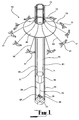
- an aerial amusement ride 10 involves conveyance of riders through the air In a manner somewhat simulating flight at an elevation sufficiently high to provide a thrilling sensation.
- the aerial amusement ride 10 comprises a tower 11 anchored to the ground 13.
- a support head 15 is mounted on the tower 13 and riders 17 are suspended from the support head 15 by way of flexible suspension links 19 for conveyance through the air about the tower.
- the riders 17 are conveyed along a path which extends around the tower 11, with the elevation of the riders being selectively variable, as will be explained later.
- the tower 11 comprises a base 21 and a column 23 mounted on the base 21.
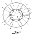
- the column 23 is of framework construction, comprising a plurality of longitudinal elements 25 connected one to another by lateral elements 26 which provide bracing, as best seen in Figure 4 of the drawings.
- Each longitudinal element 25 is of rectangular cross-section and is oriented diagonally so that two adjacent faces 27, 28 thereof are outwardly facing, as best seen in Figure 4 .
- the column 23 in this embodiment comprises a plurality of column sections disposed in series one upon another, with adjacent sections being detachably connected together.
- the height of the column which is a matter of design choice, can be established by using an appropriate number of column sections.
- the arrangement facilitates erection of the column 23, as it is merely necessary to fit one column section upon another, typically with the assistance of a crane or other suitable load lifting apparatus.
- the support head 15 comprises an inner ring structure 31 adapted for displacement along the column 23 while being fixed against rotation with respect thereto, and an outer hub structure 33 rotatably supported on the inner ring structure 31.
- the inner ring structure 31 is mounted on the column 23 for guided rolling movement therealong.
- the inner ring structure 31 comprises a peripheral frame 35 of generally circular construction extending around the column 23.
- a plurality of sets of rollers 37 are mounted on the frame 35 in two groups spaced one with respect to the other in the longitudinal direction of the column 23.
- the roller sets 37 in each group are circumferentially spaced around the column 23, with each roller set 37 corresponding to one of the longitudinal elements 25 of the column 23.
- Each roller set 37 comprises two rollers 39 positioned for rolling engagement against respective outer adjacent faces 27, 28 of the corresponding longitudinal element 25, as best seen in Figure 4 . This is achieved by supporting the rollers 39 in each set with their axis of rotation substantially at 90 degrees with respect to each other.
- the respective longitudinal element 25 defines a track and the faces 27, 28 define two track surfaces, with each roller 39 in the roller set 37 engaging a respective one of the track surfaces.
- the orientation of the two rollers 39 in each roller set 37 and also the track surfaces, ensures that the ring structure 31 is supported for guided rolling movement along the column 23 while being restrained against rotation around the column.
- the hub structure 33 comprises a hub frame 41 of generally circular construction rotatably mounted on the ring structure 31, and a plurality of outriggers 43 extending from the hub frame 41.
- a canopy covers the hub structure 33.
- the canopy 45 is shown partly cut-away in Figures 2 and 3 .
- a first drive means 51 is provided for rotating the hub structure 33 with respect to the ring structure 31, thereby rotating the hub structure 33 with respect to the column 23.
- the drive means 51 comprises an electric motor 53 and a drive wheel 55 drivingly connected to the motor 53.
- the electric motor 53 is supported on the inner ring structure 31 and the drive wheel 55 is in driving engagement with a drive ring 57 mounted on the hub frame 41.
- the drive wheel 55 comprises a rubber wheel which is adapted to frictionally engage the drive ring 57, whereby rotational torque applied to the drive wheel 55 is transmitted to the hub structure 33 through frictional engagement between the drive wheel 55 and the drive ring 57 mounted on the hub frame 41.
- a second drive means 61 is provided for displacing the support head 15, and thus the hub structure 33 forming part thereof, along the column 23.
- the second drive means 61 comprises a cable and pulley system 63 from which the support head 15 is suspended, together with a counter-weight 65 and a winch mechanism 67.
- the cable and pulley system 63 comprises a plurality of cables 71 (there being four such cables in this embodiment). One end of each cable 71 is attached to the ring structure 31 of the support head 15 and the other end of each cable is connected to the counter-weight 65. Each cable 71 passes over a respective pulley 73 mounted on the column 23 at a location above the uppermost extent of displacement of the support head 15. From the connection to the support head 15, each cable 71 passes upwardly to be routed around its respective pulley 73 and then extends downwardly to the counter-weight 65.
- the counter-weight 65 is connected to the winch mechanism 67 by way of a winch cable 75.
- the winch mechanism 67 incorporates a winch drum 68 about which the winch cable 75 can be wound and unwound.
- the counter-weight 65 is selected such that the support head 15 can travel downwardly under the Influence of gravity, with its weight parity being compensated by the counter-weight 65.
- the rate of descent of the support head 15 on the column 23 is controlled by the rate at which the winch cable 75 is unwound from the winch mechanism 67.
- the winch mechanism 67 incorporates a disc brake (not shown) operation of which can regulate the rate at which the winch cable 75 is unwound.
- the counter-weight 65 is accommodated within the open space 29 within the framework defining the column 23. This provides for compactness of construction and also allows the longitudinal elements 25 within the column 23 to be used for the purposes of guiding movement of the counter-weight as it moves upwardly and downwardly corresponding to displacement of the support head 15. To this end, the periphery of the counter-weight 65 is configured so that the counter-weight can be accommodated within the open space 29 for guided movement therealong by the longitudinal elements 25.
- both the counter-weight 65 and the winch mechanism 67 are accommodated within the confines of the tower 11.
- Each flexible suspension link 19 comprises a flexible line 83 which in this embodiment is in the form of a cable or chain, with one end of the flexible line 83 being connected to a respective one of the outriggers 43 and the other end of the flexible link 83 being connected to a respective rider carrier 81.
- the rider carriers 81 comprise harness structures in which the riders 17 can be accommodated.
- Other types of rider carriers are of course possible, including carriages in the form of seats or pods accommodating one or more riders.
- harness structures defining the rider carriers 81 in the embodiment each accommodate a single rider, It is possible to utilise a tandem or other multiple harness in which several riders may engage in the thrill of riding together in a common carrier.
- each suspension line 83 and its respective rider carrier 81 may incorporate a swivel to permit the rider to twist around an axis corresponding to the longitudinal extent of the suspension line. In this way, the rider has the option of twisting or otherwise manipulating his or her body around in order to provide further variety to the ride and thus enhance the sensation experienced during the ride.
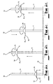
- the ride commences with the riders 17 at ground level or at an appropriate loading station near ground level, as shown in Figure 5a .
- the support head 15 is lowered by operating the winch mechanism 67 to unwind the winch cable 75 from the winch drum 68.
- the winch mechanism 67 is operated to wind in the winch cable 75, thereby pulling the counter-weight 65 downwardly and thus causing the support head 15 to move upwardly along the column 23, as illustrated in Figure 5b .
- the first drive means 51 can be actuated so as to cause the hub structure 33 to rotate about the column 23.
- This causes the riders 17 to swing outwardly on the suspension lines 83 and move through a somewhat circular path around the column 23, also as shown in Figure 5b .
- the support head 15 can be lowered as Illustrated In Figure 5c and raised as illustrated in Figure 5d in order to change the elevation of the riders as they move through the circular path about the column 23.
- the speed of rotation of the hub structure 23 can also be varied if desired to provide variation to the ride characteristics.
- the hub structure 33 rotates at about 10rpm in this embodiment
- the displacement of the support head involving movement upwardly and downwardly during the ride may be at speeds up to about 5m/s.
- the support head 15 can be lowered at a rate faster than the riders 17, thus providing situations where the riders 17 may be higher than the points at which they are attached to the ride.
- the variation in elevation during the revolving motion of the riders provides an exciting ride, particularly when regard is had to the significant height at which the ride is conducted. Further variation is available to the riders 17 during the ride through swivelling movement at the connection between the suspension line 83 and the rider carrier 81. To complete the ride, the support head 15 is lowered so as to return the riders 17 to the ground or loading platform.
- amusement ride 100 there is shown an amusement ride 100 according to an embodiment of the invention.
- the amusement ride 100 is similar in many respects to the amusement ride 10 according to the preceding embodiment and corresponding reference numerals are used to identify similar parts.
- the tower 11 comprises a base 21 and a column 23, as was the case in the preceding embodiment.
- the base 21 comprises a plurality of legs 101 extending radially outwardly, with anchoring pads 103 provided on the outer ends of the legs 101 for engagement with the ground 13.
- the base 21 also incorporates a station 105 at which riders are loaded onto, and unloaded from, the ride.
- the station 105 comprises a platform 107 which extends around the tower 11 and which is accessible by way of stairs 109.
- the base 21 also incorporates a portion 111 extending downwardly, accommodated within a hole 113 formed in the ground.
- the column 23 is of framework construction and is formed in column sections 115 connected one to another at junctions 117.
- the rider carriers 81 comprise chair structures 119 which may be fitted with an appropriate restraint system for the purposes of restraining riders in position during operation of the ride.
- the flexible suspension link 19 suspending each rider carrier 81 to a respective outrigger 43 comprises a pair of flexible lines 121 such as cables or chains.
- the flexible lines 121 are connected at their upper end to a crossbar 123 which in turn is connected to the respective outrigger 43 by way of swivel connection 125.
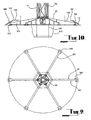
- Operation of the amusement ride 100 according to this embodiment is similar to that of amusement ride 10 according to the preceding embodiment, with the ride commencing with the support head 15 lowered into a position at which riders can enter the chairs 119 at the station 105, as shown in Figure 8 of the drawings.
- the support head is then raised into an operative condition and rotated and displaced in a similar fashion to the preceding embodiment.
- all chairs 119 are accommodated at the station 105 at the same time.
- riders enter and leave the various chairs 119 at the station at the same time.
- the station may be at a specific location, with the chairs 119 moving sequentially into and out of the station.
- the drive means for rotating the support head 15 can be utilised to rotate the chairs in an indexing fashion, with the chairs moving into and out of the station one after another. This can be advantageous in that the ride operator would than be in a better position to exercise control over the loading and unloading process, particularly with regard to the manner in which riders enter and leave each chair.
- the amusement ride 100 has been designed so that it is conducive to construction on a very large scale. Indeed, the tower 11 is approximately 60 metres in height and the diameter of the rotatable support head 15 is approximately 18 metres. The enormous size of the amusement device ensures that the riders are exposed to an extreme height during the ride, thereby enhancing the sensation experienced during the ride.
- the flexible suspension link 19 comprises two lines 131 suspended from a cross member 133 connected by pivot connection 135 to outrigger 43.
- the pivot connection 135 facilitates outward swinging motion of the rider carrier.
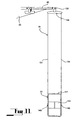
- the rider carrier 81 comprises a capsule 141 in which several riders can be accommodated.
- the capsule 141 incorporates seating 143 for riders in the capsule.
- the capsule 141 is rotatable supported between two trunnions 145, with each trunnion 145 being connected to one of the lines 131. With this arrangement, the trunnions 145 define a rotational axis about which the capsule 141 can rotate.
- the capsule 141 has an outer periphery fitted with control devices in the form of a pair of vanes, not shown in Figure 11 .
- the vanes cause the capsule 141 to rotate about the rotational axis upon movement of the capsule through the air with rotation of the hub structure 33.
- the angle of attack of the vanes determines the speed of rotation of the capsule.
- the direction of rotation may be altered by altering the attitude of the vanes; that is, by facing them in an opposite direction relative to the rotational axis of the capsule.
- the control may be achieved by way of a lever mechanism located within the capsule 141 and operatively connected to one or both vanes. This presents the rider with an opportunity to control his or her own ride, thereby providing variation to the ride and further enhancing the sensation experienced on the ride.
- the locking mechanism may be controlled by the ride operator who may provide the rider with the choice as to whether or not the rotational function will be employed during the ride.
- the rotatable capsule provides a further axis of rotation during the ride, providing variety and thus a generally more exciting ride.
- the feature may also be conducive to repeat business, as riders may wish to develop their skills over time in controlling the ride.
- the amusement ride according to the illustrated embodiments of the invention can be constructed on a large scale such that the riders are elevated to a height which in itself provides excitement.
- the amusement ride is of a design which is conducive to construction on such a large scale. It incorporates a simple yet highly effective arrangement for driving the support head 15 both rotationally for moving the riders around through the air, and also linearly for varying the elevation of the riders during the ride as well as raising and lowering the riders with respect to the ground or a station at which the riders embark upon, and disembark from, the ride.
Landscapes
- Jib Cranes (AREA)
- Buildings Adapted To Withstand Abnormal External Influences (AREA)
- Addition Polymer Or Copolymer, Post-Treatments, Or Chemical Modifications (AREA)
- Eye Examination Apparatus (AREA)
- Lubrication Of Internal Combustion Engines (AREA)
- Non-Silver Salt Photosensitive Materials And Non-Silver Salt Photography (AREA)
- Types And Forms Of Lifts (AREA)
Claims (40)
- Flug-Fahrgeschäft des Typs, bei dem Fahrgäste (17) in Fahrgastträgern (81) über dem Boden durch die Luft in Drehung um eine Säule (23) eines Turms (11) herum mittels einer Tragestruktur (15) befördert werden, die die Fahrgastträger (81) in einem radialen Abstand zu der Säule (23) an Verbindungsgliedern (19) trägt, die zulassen, dass sich die Fahrgastträger (81) von der Säule (23) radial nach außen bewegen, wenn die Geschwindigkeit des Fahrgeschäftes zunimmt, dadurch gekennzeichnet, dass die Säule (23) eine offene Rahmenkonstruktion hat, bei der Längselemente (25) durch Querelemente (26) mit offenen Räumen zwischen den Längs- und den Querelementen (25, 26) miteinander verbunden und verstrebt sind.
- Fahrgeschäft nach Anspruch 1, wobei die Säule (23) eine Längsreihe von Säulenabschnitten (115) umfasst, die jeweils die erwähnte offene Rahmenkonstruktion haben.
- Fahrgeschäft nach Anspruch 2, wobei die Säulenabschnitte (115) lösbar miteinander verbunden sind.
- Fahrgeschäft nach Anspruch 1, 2 oder 3, wobei die offene Rahmenkonstruktion der Säule (23) so ist, dass ein offener Raum (29) im Inneren der Säule (23) bereitgestellt wird.
- Fahrgeschäft nach einem der vorangehenden Ansprüche, wobei die Verbindungsglieder (19) flexible Aufhängungs-Verbindungsglieder aufweisen.
- Fahrgeschäft nach Anspruch 5, wobei jedes flexible Verbindungsglied (19) wenigstens eine flexible Leine aufweist.
- Fahrgeschäft nach einem der vorangehenden Ansprüche, wobei jeder Fahrgastträger (81) mit der Tragestruktur (15) zur Schwenkbewegung in Bezug darauf verbunden ist.
- Fahrgeschäft nach Anspruch 7, wobei die Schwenkbewegung durch eine Schwenkverbindung zwischen dem Verbindungsglied (19) und der Tragestruktur (15) ermöglicht wird.
- Fahrgeschäft nach Anspruch 7 oder 8, wobei die Schwenkbewegung Drehung um eine Achse herum umfasst, die einer Längsachse des Verbindungsgliedes (19) entspricht.
- Fahrgeschäft nach einen der vorangehenden Ansprüche, wobei jeder Fahrgastträger (81) so eingerichtet ist, dass er sich um eine Drehachse quer zu einer Längsachse des Verbindungsgliedes (19) dreht.
- Fahrgeschäft nach Anspruch 10, wobei der Fahrgastträger (81) mit einer Steuervorrichtung (147) versehen ist, um eine Drehbewegung um die Drehachse herum während einer Bewegung des Fahrgastträgers (81) durch die Luft zu vermitteln.
- Fahrgeschäft nach Anspruch 11, das des Weiteren Mittel aufweist, um einem Fahrgast (17) zu ermöglichen, die Steuervorrichtung (147) während der Fahrt selektiv zu betätigen, um Veränderung der Fahrt zu ermöglichen.
- Fahrgeschäft nach einem der vorangehenden Ansprüche, wobei der Turm (11) einen Sockel (21) umfasst und die Säule (23) aufrecht auf dem Sockel (21) steht.
- Fahrgeschäft nach Anspruch 13, wobei der Sockel (21) so eingerichtet ist, dass er lösbar am Boden verankert wird.
- Fahrgeschäft nach einem der vorangehenden Ansprüche, wobei sich der Turm (11) bis zu einer Höhe von wenigstens 30 m erstreckt.
- Fahrgeschäft nach Anspruch 15, wobei der Turm (11) eine Höhe von ungefähr 60 m hat.
- Fahrgeschäft nach einem der vorangehenden Ansprüche, wobei die Tragestruktur (15) eine Vielzahl von Auslegern (43) aufweist, die jeweils ein entsprechendes der Verbindungsglieder (19) tragen, das einen entsprechenden der Fahrgastträger (81) trägt.
- Fahrgeschäft nach einem der vorangehenden Ansprüche, wobei die Tragestruktur (15) eine Nabenstruktur (33) aufweist, die von dem Turm (11) zur Drehung in Bezug darauf getragen wird, und das Fahrgeschäft des Weiteren eine erste Antriebseinrichtung (51) zum Drehen der Nabenstruktur (33) in Bezug auf den Turm (11) aufweist.
- Fahrgeschäft nach einem der vorangehenden Ansprüche, wobei die Tragestruktur (15) so angeordnet ist, dass sie an dem Turm (11) entlang verschoben wird, und das Fahrgeschäft des Weiteren eine zweite Antriebseinrichtung (61) zum Verschieben der Tragestruktur (15) an dem Turm (11) entlang aufweist.
- Fahrgeschäft nach den Ansprüchen 18 und 19, wobei die Nabenstruktur (33) drehbar an einer Ringstruktur (31) gelagert ist und für eine Verschiebung entlang des Turms (11) geeignet ist, während sie gegen Rotation in Bezug auf den Turm (11) fixiert ist.
- Fahrgeschäft nach Anspruch 20, wobei die Ringstruktur (31) an der Säule (23) zur geführten Rollbewegung an ihr entlang angebracht ist.
- Fahrgeschäft nach Anspruch 20, wobei die Ringstruktur (31) Rollen (37) aufweist, die in Rolleingriff mit Bahnen an der Säule (23) sind, die durch wenigstens einige der Längselemente (25) innerhalb der Rahmenkonstruktion gebildet werden.
- Fahrgeschäft nach einem der Ansprüche 19 bis 22, das des Weiteren ein Gegengewicht (65) umfasst, das so angeordnet ist, dass es an dem Turm (11) entlang läuft, um das Gewicht der Tragestruktur (15) auszugleichen.
- Fahrgeschäft nach Anspruch 23, wobei das Gegengewicht (65) so angeordnet ist, dass es innerhalb des Turms (11) läuft.
- Fahrgeschäft nach Anspruch 23 oder 24, wobei Bewegung des Gegengewichtes (65) durch Elemente der Säule (13) geführt wird.
- Fahrgeschäft nach Anspruch 25, wobei Bewegung des Gegengewichtes (65) durch die Längselemente (25) der Säule (23) geführt wird.
- Fahrgeschäft nach Anspruch 18 oder nach einem Ansprüche 19 bis 26 in Abhängigkeit von Anspruch 18, wobei die erste Antriebseinrichtung (51) ein Antriebsrad (55) und einen Motor (53) zum Drehen des Antriebsrades (55) aufweist und das Antriebsrad (55) in Antriebseingriff mit der Nabenstruktur (33) ist, wodurch Drehung des Antriebsrades (55) Drehung der Nabenstruktur (33) in Bezug auf den Turm (11) verursacht.
- Fahrgeschäft nach einem der Ansprüche 19 bis 27, wobei die zweite Antriebseinrichtung (61) so betrieben werden kann, dass sie selektiv verursacht, dass die Tragestruktur (15) Verschiebung in Bezug auf den Turm (11) erfährt.
- Fahrgeschäft nach Anspruch 28, wobei die zweite Antriebseinrichtung (61) ein Seil- und Rollensystem (63), an dem die Tragestruktur (15) aufgehängt ist, sowie einen Windenmechanismus (67) aufweist, wobei das Seil- und Rollensystem (63) eine Rolle (73), die an dem Turm (11) oberhalb der obersten Ausdehnung der Verschiebung der Tragestruktur (15) angebracht ist, und ein Seil (71) aufweist, dessen eines Ende mit der Tragestruktur (15) verbunden ist, wobei sich das Seil (71) von der Tragestruktur (15) nach oben, um die Rolle (73) herum und so nach unten verläuft, dass es mit dem Windenmechanismus (67) betrieben werden kann.
- Fahrgeschäft nach den Ansprüchen 23 und 29, wobei das Seil (71) mit dem Gegengewicht (65) verbunden ist und das Gegengewicht (65) über ein Windenseil (71) mit dem Windenmechanismus (67) verbunden ist.
- Fahrgeschäft nach Anspruch 29 oder 30, wobei das System (63) aus Seil und Rolle eine Vielzahl von Seilen (71) und dazugehörigen Rollen (73) umfasst und jedes Seil (71) an einem Ende mit der Tragestruktur (15) verbunden ist, nach oben über seine entsprechende Rolle (73) und so nach unten verläuft, dass es mit dem Windenmechanismus (67) betrieben werden kann.
- Fahrgeschäft nach Anspruch 4 gemeinsam mit Anspruch 30 oder 31, wobei das Gegengewicht (65) innerhalb des offenen Raumes (29) in der Säule (23) aufgenommen ist.
- Fahrgeschäft nach Anspruch 4 gemeinsam mit einem der Ansprüche 29 bis 32, wobei der Windenmechanismus (67) innerhalb des offenen Raumes (29) in der Säule (23) aufgenommen ist.
- Fahrgeschäft nach einem der Ansprüche 29 bis 33, das des Weiteren einen Bremsmechanismus aufweist, der mit dem Windenmechanismus (67) verbunden ist, um Abwärtsbewegung der Tragestruktur (15) in Bezug auf den Turm (11) zu verzögern, wobei der Bremsmechanismus eine Scheibenbremse umfasst, die an dem Windenmechanismus (67) vorhanden ist.
- Fahrgeschäft nach einem der vorangehenden Ansprüche, das des Weiteren eine an den Sockel des Turms (11) angrenzende Einsteigestation (105) aufweist, an der Fahrgäste (17) in das Fahrgeschäft einsteigen oder aus ihm aussteigen können.
- Fahrgeschäft nach Anspruch 35, wobei die Einsteigestation (105) eine Plattform (107) aufweist, die um den Turm (11) herum verläuft.
- Fahrgeschäft nach Anspruch 35 oder 36, wobei die Einsteigestation (105) eine Plattform (107) und Treppen (109) für den Zugang zu der Plattform (107) aufweist.
- Fahrgeschäft nach einem der vorangehenden Ansprüche, wobei jedes der Längselemente (25) ein Paar aneinandergrenzender Flächen (27, 28) außerhalb der Säule (23) aufweist.
- Fahrgeschäft nach einem der vorangehenden Ansprüche, wobei jedes der Längselemente (25) einen rechteckigen Querschnitt hat.
- Fahrgeschäft nach einem der vorangehenden Ansprüche, wobei jedes der Längselemente (25) aufrecht angeordnet ist.
Applications Claiming Priority (3)
| Application Number | Priority Date | Filing Date | Title |
|---|---|---|---|
| AT1362003 | 2003-01-29 | ||
| AT1362003 | 2003-01-29 | ||
| PCT/AU2004/000099 WO2004067126A1 (en) | 2003-01-29 | 2004-01-29 | Amusement ride |
Publications (3)
| Publication Number | Publication Date |
|---|---|
| EP1590056A1 EP1590056A1 (de) | 2005-11-02 |
| EP1590056A4 EP1590056A4 (de) | 2007-01-17 |
| EP1590056B1 true EP1590056B1 (de) | 2008-05-21 |
Family
ID=32777512
Family Applications (1)
| Application Number | Title | Priority Date | Filing Date |
|---|---|---|---|
| EP04706095A Revoked EP1590056B1 (de) | 2003-01-29 | 2004-01-29 | Fahrgeschäft |
Country Status (4)
| Country | Link |
|---|---|
| EP (1) | EP1590056B1 (de) |
| AT (1) | ATE395958T1 (de) |
| DE (1) | DE602004013921D1 (de) |
| WO (1) | WO2004067126A1 (de) |
Families Citing this family (6)
| Publication number | Priority date | Publication date | Assignee | Title |
|---|---|---|---|---|
| PL1800723T3 (pl) | 2005-12-21 | 2010-09-30 | Ronald Bussink Amusement Design Gmbh | Instalacja do przejażdżek rozrywkowych |
| DE602006013932D1 (de) | 2006-01-19 | 2010-06-10 | Ronald Bussink Amusement Des | Fahrgeschäft |
| GB201315920D0 (en) * | 2013-09-06 | 2013-10-23 | Pondorfer Walter | Tower construction |
| RU2757232C2 (ru) * | 2020-03-18 | 2021-10-12 | Станислав Алексеевич Козлов | Аттракцион "эвольвентный маятник" |
| CN112044087B (zh) * | 2020-09-23 | 2021-09-17 | 广东海洋大学 | 一种基于上位机的旋转摇摆伞控制系统 |
| CN115607974A (zh) * | 2022-10-24 | 2023-01-17 | 南京派格斯游乐设备有限公司 | 一种天空飞翔游乐设备 |
Family Cites Families (6)
| Publication number | Priority date | Publication date | Assignee | Title |
|---|---|---|---|---|
| US4576373A (en) | 1983-10-24 | 1986-03-18 | Robert Spieldiener | Aerial amusement ride |
| US5658201A (en) * | 1995-11-13 | 1997-08-19 | Airsurfer, Inc. | Swinging boom amusement ride |
| US5709606A (en) * | 1996-03-20 | 1998-01-20 | Ehrman; Richard Eugene | Rotatable swing set |
| US5957779A (en) * | 1996-10-08 | 1999-09-28 | Larson; Walter F. | Tower |
| US5820469A (en) * | 1997-05-30 | 1998-10-13 | Chance Industries, Inc. | Flying vehicle ride |
| US6569024B2 (en) * | 2001-07-23 | 2003-05-27 | Mark Kleimeyer | Giant swing amusement ride with oppositely pivoting boom arm and cam arm |
-
2004
- 2004-01-29 EP EP04706095A patent/EP1590056B1/de not_active Revoked
- 2004-01-29 WO PCT/AU2004/000099 patent/WO2004067126A1/en not_active Ceased
- 2004-01-29 AT AT04706095T patent/ATE395958T1/de not_active IP Right Cessation
- 2004-01-29 DE DE602004013921T patent/DE602004013921D1/de not_active Expired - Lifetime
Also Published As
| Publication number | Publication date |
|---|---|
| WO2004067126A1 (en) | 2004-08-12 |
| EP1590056A1 (de) | 2005-11-02 |
| ATE395958T1 (de) | 2008-06-15 |
| EP1590056A4 (de) | 2007-01-17 |
| DE602004013921D1 (de) | 2008-07-03 |
Similar Documents
| Publication | Publication Date | Title |
|---|---|---|
| US7666103B2 (en) | Amusement ride | |
| US5527223A (en) | Swing type amusement ride | |
| US5827124A (en) | Rocking boom amusement ride | |
| EP0656801B1 (de) | Vergnügungsanlage | |
| US6440002B1 (en) | Top loading swing type amusement ride | |
| US5989127A (en) | Oscillating boom amusement ride | |
| US7594473B2 (en) | Wheel hub rider conveyance | |
| EP3229931B1 (de) | Hochwinkelige angebundene rutsche mit freiem fall und schwung mit variablem radius | |
| US10780360B2 (en) | High angle tethered slide with freefall drop and variable radius swing | |
| WO2007139508A1 (en) | An amusement ride | |
| CA2181352C (en) | Swing type amusement ride with pendulum damper | |
| US20080318733A1 (en) | Acrobatic elevated-path amusement device | |
| EP1590056A1 (de) | Fahrgeschäft | |
| US10717015B2 (en) | High angle tethered slide with freefall drop and variable radius swing | |
| EP2498883B1 (de) | Vorrichtung für fahrgeschäfte | |
| US2304341A (en) | Roundabout | |
| WO2014141195A1 (en) | Amusement ride | |
| EP4442340B1 (de) | Fahrgeschäfte | |
| RU2859932C1 (ru) | Аттракцион ("хилл-н-ролл") | |
| RU242812U1 (ru) | Аттракцион ("хилл-н-ролл") | |
| HK1146250A (en) | Wheel hub rider conveyance | |
| JPH07185138A (ja) | 昇降式遊戯装置 | |
| JPS60182979A (ja) | レジヤ−乗物装置 |
Legal Events
| Date | Code | Title | Description |
|---|---|---|---|
| PUAI | Public reference made under article 153(3) epc to a published international application that has entered the european phase |
Free format text: ORIGINAL CODE: 0009012 |
|
| 17P | Request for examination filed |
Effective date: 20050826 |
|
| AK | Designated contracting states |
Kind code of ref document: A1 Designated state(s): AT BE BG CH CY CZ DE DK EE ES FI FR GB GR HU IE IT LI LU MC NL PT RO SE SI SK TR |
|
| AX | Request for extension of the european patent |
Extension state: AL LT LV MK |
|
| DAX | Request for extension of the european patent (deleted) | ||
| A4 | Supplementary search report drawn up and despatched |
Effective date: 20061215 |
|
| RIC1 | Information provided on ipc code assigned before grant |
Ipc: A63G 1/28 20060101AFI20061211BHEP Ipc: A63G 1/44 20060101ALI20061211BHEP |
|
| 17Q | First examination report despatched |
Effective date: 20070129 |
|
| TCNL | Nl: translation of patent claims filed | ||
| GRAP | Despatch of communication of intention to grant a patent |
Free format text: ORIGINAL CODE: EPIDOSNIGR1 |
|
| TPAC | Observations filed by third parties |
Free format text: ORIGINAL CODE: EPIDOSNTIPA |
|
| GRAS | Grant fee paid |
Free format text: ORIGINAL CODE: EPIDOSNIGR3 |
|
| GRAA | (expected) grant |
Free format text: ORIGINAL CODE: 0009210 |
|
| AK | Designated contracting states |
Kind code of ref document: B1 Designated state(s): AT BE BG CH CY CZ DE DK EE ES FI FR GB GR HU IE IT LI LU MC NL PT RO SE SI SK TR |
|
| REG | Reference to a national code |
Ref country code: GB Ref legal event code: FG4D |
|
| REG | Reference to a national code |
Ref country code: CH Ref legal event code: EP |
|
| REF | Corresponds to: |
Ref document number: 602004013921 Country of ref document: DE Date of ref document: 20080703 Kind code of ref document: P |
|
| PLCP | Request for limitation filed |
Free format text: ORIGINAL CODE: EPIDOSNLIM1 |
|
| RAP2 | Party data changed (patent owner data changed or rights of a patent transferred) |
Owner name: FUNTIME HANDELS GMBH |
|
| REG | Reference to a national code |
Ref country code: CH Ref legal event code: NV Representative=s name: MICHELI & CIE SA |
|
| PLBI | Opposition filed |
Free format text: ORIGINAL CODE: 0009260 |
|
| PLCT | Request for limitation of patent deemed not filed due to filing of opposition |
Free format text: ORIGINAL CODE: 0009234 |
|
| REG | Reference to a national code |
Ref country code: IE Ref legal event code: FG4D |
|
| 26 | Opposition filed |
Opponent name: V.O.F. J.H.A. VAN DER BEEK Effective date: 20080728 |
|
| LIM4 | Request for limitation deemed not have been filed (opposition pending/filed) |
Free format text: SEQUENCE NO: 1; FILED DURING OPPOSITION PERIOD Filing date: 20080702 |
|
| PG25 | Lapsed in a contracting state [announced via postgrant information from national office to epo] |
Ref country code: SI Free format text: LAPSE BECAUSE OF FAILURE TO SUBMIT A TRANSLATION OF THE DESCRIPTION OR TO PAY THE FEE WITHIN THE PRESCRIBED TIME-LIMIT Effective date: 20080521 |
|
| NLT2 | Nl: modifications (of names), taken from the european patent patent bulletin |
Owner name: FUNTIME HANDELS GMBH Effective date: 20080730 |
|
| REG | Reference to a national code |
Ref country code: GB Ref legal event code: 732E |
|
| PG25 | Lapsed in a contracting state [announced via postgrant information from national office to epo] |
Ref country code: ES Free format text: LAPSE BECAUSE OF FAILURE TO SUBMIT A TRANSLATION OF THE DESCRIPTION OR TO PAY THE FEE WITHIN THE PRESCRIBED TIME-LIMIT Effective date: 20080901 Ref country code: FI Free format text: LAPSE BECAUSE OF FAILURE TO SUBMIT A TRANSLATION OF THE DESCRIPTION OR TO PAY THE FEE WITHIN THE PRESCRIBED TIME-LIMIT Effective date: 20080521 |
|
| NLR1 | Nl: opposition has been filed with the epo |
Opponent name: V.O.F. J.H.A. VAN DER BEEK |
|
| PG25 | Lapsed in a contracting state [announced via postgrant information from national office to epo] |
Ref country code: AT Free format text: LAPSE BECAUSE OF FAILURE TO SUBMIT A TRANSLATION OF THE DESCRIPTION OR TO PAY THE FEE WITHIN THE PRESCRIBED TIME-LIMIT Effective date: 20080521 |
|
| NLR4 | Nl: receipt of corrected translation in the netherlands language at the initiative of the proprietor of the patent | ||
| NLS | Nl: assignments of ep-patents |
Owner name: FUNTIME HANDELS GMBH Effective date: 20081020 |
|
| PG25 | Lapsed in a contracting state [announced via postgrant information from national office to epo] |
Ref country code: SE Free format text: LAPSE BECAUSE OF FAILURE TO SUBMIT A TRANSLATION OF THE DESCRIPTION OR TO PAY THE FEE WITHIN THE PRESCRIBED TIME-LIMIT Effective date: 20080821 Ref country code: PT Free format text: LAPSE BECAUSE OF FAILURE TO SUBMIT A TRANSLATION OF THE DESCRIPTION OR TO PAY THE FEE WITHIN THE PRESCRIBED TIME-LIMIT Effective date: 20081021 Ref country code: DK Free format text: LAPSE BECAUSE OF FAILURE TO SUBMIT A TRANSLATION OF THE DESCRIPTION OR TO PAY THE FEE WITHIN THE PRESCRIBED TIME-LIMIT Effective date: 20080521 Ref country code: CZ Free format text: LAPSE BECAUSE OF FAILURE TO SUBMIT A TRANSLATION OF THE DESCRIPTION OR TO PAY THE FEE WITHIN THE PRESCRIBED TIME-LIMIT Effective date: 20080521 |
|
| PG25 | Lapsed in a contracting state [announced via postgrant information from national office to epo] |
Ref country code: SK Free format text: LAPSE BECAUSE OF FAILURE TO SUBMIT A TRANSLATION OF THE DESCRIPTION OR TO PAY THE FEE WITHIN THE PRESCRIBED TIME-LIMIT Effective date: 20080521 Ref country code: BE Free format text: LAPSE BECAUSE OF FAILURE TO SUBMIT A TRANSLATION OF THE DESCRIPTION OR TO PAY THE FEE WITHIN THE PRESCRIBED TIME-LIMIT Effective date: 20080521 Ref country code: RO Free format text: LAPSE BECAUSE OF FAILURE TO SUBMIT A TRANSLATION OF THE DESCRIPTION OR TO PAY THE FEE WITHIN THE PRESCRIBED TIME-LIMIT Effective date: 20080521 |
|
| PLBI | Opposition filed |
Free format text: ORIGINAL CODE: 0009260 |
|
| PLBI | Opposition filed |
Free format text: ORIGINAL CODE: 0009260 |
|
| REG | Reference to a national code |
Ref country code: CH Ref legal event code: PK Free format text: DER EINTRAG BESCHRAENKUNG GILT ALS NICHT EINGELEGT ERFOLGTE IRRUEMLICH |
|
| PLAX | Notice of opposition and request to file observation + time limit sent |
Free format text: ORIGINAL CODE: EPIDOSNOBS2 |
|
| 26 | Opposition filed |
Opponent name: ANTONIO ZAMPERLA S.P.A. Effective date: 20090223 Opponent name: V.O.F. J.H.A. VAN DER BEEK Effective date: 20080728 |
|
| 26 | Opposition filed |
Opponent name: KERMIS- EN MACHINEBOUW GAASENDAM EUROPE B.V. Effective date: 20090220 Opponent name: V.O.F. J.H.A. VAN DER BEEK Effective date: 20080728 Opponent name: ANTONIO ZAMPERLA S.P.A. Effective date: 20090223 |
|
| PG25 | Lapsed in a contracting state [announced via postgrant information from national office to epo] |
Ref country code: BG Free format text: LAPSE BECAUSE OF FAILURE TO SUBMIT A TRANSLATION OF THE DESCRIPTION OR TO PAY THE FEE WITHIN THE PRESCRIBED TIME-LIMIT Effective date: 20080821 Ref country code: EE Free format text: LAPSE BECAUSE OF FAILURE TO SUBMIT A TRANSLATION OF THE DESCRIPTION OR TO PAY THE FEE WITHIN THE PRESCRIBED TIME-LIMIT Effective date: 20080521 |
|
| PLBP | Opposition withdrawn |
Free format text: ORIGINAL CODE: 0009264 |
|
| NLR1 | Nl: opposition has been filed with the epo |
Opponent name: KERMIS- EN MACHINEBOUW GAASENDAM EUROPE B.V. Opponent name: ANTONIO ZAMPERLA S.P.A. Opponent name: V.O.F. J.H.A. VAN DER BEEK |
|
| PG25 | Lapsed in a contracting state [announced via postgrant information from national office to epo] |
Ref country code: MC Free format text: LAPSE BECAUSE OF NON-PAYMENT OF DUE FEES Effective date: 20090131 |
|
| PLBB | Reply of patent proprietor to notice(s) of opposition received |
Free format text: ORIGINAL CODE: EPIDOSNOBS3 |
|
| REG | Reference to a national code |
Ref country code: IE Ref legal event code: MM4A |
|
| PG25 | Lapsed in a contracting state [announced via postgrant information from national office to epo] |
Ref country code: IE Free format text: LAPSE BECAUSE OF NON-PAYMENT OF DUE FEES Effective date: 20090129 |
|
| RAP2 | Party data changed (patent owner data changed or rights of a patent transferred) |
Owner name: COTTINGHAM AGENCIES LTD. |
|
| PG25 | Lapsed in a contracting state [announced via postgrant information from national office to epo] |
Ref country code: GR Free format text: LAPSE BECAUSE OF FAILURE TO SUBMIT A TRANSLATION OF THE DESCRIPTION OR TO PAY THE FEE WITHIN THE PRESCRIBED TIME-LIMIT Effective date: 20080822 |
|
| RDAF | Communication despatched that patent is revoked |
Free format text: ORIGINAL CODE: EPIDOSNREV1 |
|
| APAH | Appeal reference modified |
Free format text: ORIGINAL CODE: EPIDOSCREFNO |
|
| APBM | Appeal reference recorded |
Free format text: ORIGINAL CODE: EPIDOSNREFNO |
|
| APBP | Date of receipt of notice of appeal recorded |
Free format text: ORIGINAL CODE: EPIDOSNNOA2O |
|
| APBQ | Date of receipt of statement of grounds of appeal recorded |
Free format text: ORIGINAL CODE: EPIDOSNNOA3O |
|
| PG25 | Lapsed in a contracting state [announced via postgrant information from national office to epo] |
Ref country code: LU Free format text: LAPSE BECAUSE OF NON-PAYMENT OF DUE FEES Effective date: 20090129 |
|
| PG25 | Lapsed in a contracting state [announced via postgrant information from national office to epo] |
Ref country code: HU Free format text: LAPSE BECAUSE OF FAILURE TO SUBMIT A TRANSLATION OF THE DESCRIPTION OR TO PAY THE FEE WITHIN THE PRESCRIBED TIME-LIMIT Effective date: 20081122 |
|
| PG25 | Lapsed in a contracting state [announced via postgrant information from national office to epo] |
Ref country code: TR Free format text: LAPSE BECAUSE OF FAILURE TO SUBMIT A TRANSLATION OF THE DESCRIPTION OR TO PAY THE FEE WITHIN THE PRESCRIBED TIME-LIMIT Effective date: 20080521 |
|
| PG25 | Lapsed in a contracting state [announced via postgrant information from national office to epo] |
Ref country code: CY Free format text: LAPSE BECAUSE OF FAILURE TO SUBMIT A TRANSLATION OF THE DESCRIPTION OR TO PAY THE FEE WITHIN THE PRESCRIBED TIME-LIMIT Effective date: 20080521 |
|
| APBU | Appeal procedure closed |
Free format text: ORIGINAL CODE: EPIDOSNNOA9O |
|
| APBC | Information on closure of appeal procedure deleted |
Free format text: ORIGINAL CODE: EPIDOSDNOA9O |
|
| PGFP | Annual fee paid to national office [announced via postgrant information from national office to epo] |
Ref country code: IT Payment date: 20120126 Year of fee payment: 9 |
|
| PGFP | Annual fee paid to national office [announced via postgrant information from national office to epo] |
Ref country code: FR Payment date: 20130304 Year of fee payment: 10 Ref country code: DE Payment date: 20130129 Year of fee payment: 10 Ref country code: GB Payment date: 20130131 Year of fee payment: 10 Ref country code: CH Payment date: 20130118 Year of fee payment: 10 |
|
| APBU | Appeal procedure closed |
Free format text: ORIGINAL CODE: EPIDOSNNOA9O |
|
| REG | Reference to a national code |
Ref country code: DE Ref legal event code: R064 Ref document number: 602004013921 Country of ref document: DE Ref country code: DE Ref legal event code: R103 Ref document number: 602004013921 Country of ref document: DE |
|
| PGFP | Annual fee paid to national office [announced via postgrant information from national office to epo] |
Ref country code: NL Payment date: 20130125 Year of fee payment: 10 |
|
| RDAG | Patent revoked |
Free format text: ORIGINAL CODE: 0009271 |
|
| STAA | Information on the status of an ep patent application or granted ep patent |
Free format text: STATUS: PATENT REVOKED |
|
| REG | Reference to a national code |
Ref country code: CH Ref legal event code: PL |
|
| 27W | Patent revoked |
Effective date: 20130514 |
|
| GBPR | Gb: patent revoked under art. 102 of the ep convention designating the uk as contracting state |
Effective date: 20130514 |
|
| REG | Reference to a national code |
Ref country code: DE Ref legal event code: R107 Ref document number: 602004013921 Country of ref document: DE Effective date: 20130926 |
|
| PG25 | Lapsed in a contracting state [announced via postgrant information from national office to epo] |
Ref country code: LI Free format text: LAPSE BECAUSE OF THE APPLICANT RENOUNCES Effective date: 20080521 Ref country code: CH Free format text: LAPSE BECAUSE OF THE APPLICANT RENOUNCES Effective date: 20080521 |