EP1589500A2 - Automatic cup type beverage vending machine - Google Patents
Automatic cup type beverage vending machine Download PDFInfo
- Publication number
- EP1589500A2 EP1589500A2 EP05252313A EP05252313A EP1589500A2 EP 1589500 A2 EP1589500 A2 EP 1589500A2 EP 05252313 A EP05252313 A EP 05252313A EP 05252313 A EP05252313 A EP 05252313A EP 1589500 A2 EP1589500 A2 EP 1589500A2
- Authority
- EP
- European Patent Office
- Prior art keywords
- cup
- shaking
- ice
- vending machine
- liquid material
- Prior art date
- Legal status (The legal status is an assumption and is not a legal conclusion. Google has not performed a legal analysis and makes no representation as to the accuracy of the status listed.)
- Withdrawn
Links
Images




Classifications
-
- G—PHYSICS
- G07—CHECKING-DEVICES
- G07F—COIN-FREED OR LIKE APPARATUS
- G07F13/00—Coin-freed apparatus for controlling dispensing or fluids, semiliquids or granular material from reservoirs
- G07F13/06—Coin-freed apparatus for controlling dispensing or fluids, semiliquids or granular material from reservoirs with selective dispensing of different fluids or materials or mixtures thereof
- G07F13/065—Coin-freed apparatus for controlling dispensing or fluids, semiliquids or granular material from reservoirs with selective dispensing of different fluids or materials or mixtures thereof for drink preparation
-
- G—PHYSICS
- G07—CHECKING-DEVICES
- G07F—COIN-FREED OR LIKE APPARATUS
- G07F13/00—Coin-freed apparatus for controlling dispensing or fluids, semiliquids or granular material from reservoirs
- G07F13/10—Coin-freed apparatus for controlling dispensing or fluids, semiliquids or granular material from reservoirs with associated dispensing of containers, e.g. cups or other articles
Definitions
- the present invention relates to an automatic cup type beverage vending machine which sells a beverage prepared by mixing a liquid material, for example, of a coffee taste or a fruit taste with small pieces of ice.
- An automatic cup type beverage vending machine which sells a cold beverage by feeding a liquid material into a cup in which the beverage is to be contained, and throwing ice in solid form made by an ice maker into the cup. In this case, the ice is thrown into the cup for the purpose of cooling the beverage and is not usually drunk together with the beverage.
- a vending machine is known in which ice crushed into small pieces is mixed with a liquid material in a cup to prepare a beverage such that ice can be drunk together with the liquid ---(see, for example, Japanese Patent Publication No. 2003-303371).
- a beverage in which ice is finely mixed in a liquid is prepared in such a manner that a liquid material is mixed with crushed ice in a mixer while ice is being crushed by the mixer.
- the ice cannot be finely mixed with the liquid.
- the beverage prepared in this way is inferior to commodities sold in beverage stores in terms of touch to the tongue and palate and appearance. If a mechanism for agitating a beverage by inserting an agitating member in a cup to rotate it is used, it is possible to finely mix small pieces of ice and a liquid material.
- a beverage in which small pieces of ice and a liquid material are mixed is not in a complete liquid form but in a semisolid form. Therefore, parts of small pieces of ice and a liquid material are left in an insufficiently mixed state if the agitating member is rotated only at a predetermined position, resulting in failure to uniformly mix the pieces of ice and the liquid material through the entire beverage.
- An object of the present invention is to provide an automatic cup type beverage vending machine capable of mixing small pieces of ice and a liquid material finely and uniformly through the entire beverage.
- an automatic cup type beverage vending machine in which a liquid material and small pieces of ice are agitated in a cup for containing a beverage to prepare a beverage in which the liquid material and small pieces of ice are mixed with each other, the vending machine having material supply means of supplying a liquid material or a powder material for forming a liquid material into the cup, small ice piece supply means of supplying small pieces of ice into the cup, agitation means of agitating the liquid material and small pieces of ice in the cup, and shaking means of shaking the cup in a predetermined direction at the time of preparation of the beverage.
- the liquid material and small pieces of ice in the cup are agitated by the agitation means and the cup is shaken by the shaking means.
- Mixing of the liquid material and small pieces of ice can be performed not only by agitation of the liquid material and small pieces of ice but also by shaking of the cup. Therefore, the liquid material and small pieces of ice can be mixed uniformly and finely with each other in the entire beverage and any parts of them are not left in an insufficiently mixed state.
- a beverage can be prepared which is not inferior in terms of touch to the tongue and palate and appearance to one prepared by mixing a liquid material and crushed ice while crushing ice by a mixer as in a beverage store for example.
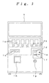
- FIGs. 1 through 11 show an embodiment of the present invention.
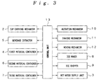
- An automatic cup type beverage vending machine shown in Figs. 1 through 11 is constituted by an automatic vending machine body 1, a cup carrying mechanism 2 for carrying cups A, a hot water supply unit 3 for producing hot water, a first material container 4 for storing coffee beans as a raw material, a beverage extractor 5 for extracting a coffee solution as a beverage material, a second material container 6 for storing sugar as a beverage material, a third material container 7 for storing cream as a beverage material, an ice maker 8 for making solid blocks of ice, an ice chipper 9 for forming small pieces of ice by chipping the ice made by ice maker 8, an agitation mechanism 10 for agitating a beverage, a shaking mechanism 11 for shaking each cup A, a moving mechanism 12 for moving the shaking mechanism 11 in the widthwise direction of the automatic vending machine body 1, and a control unit 13 for controlling beverage preparation operations.
- the automatic vending machine body 1 is formed so as to be openable and closable at the front side.
- a plurality of article samples 1a representing various coffee beverages In the front face of the automatic vending machine body 1 are provided a plurality of article samples 1a representing various coffee beverages, a plurality of article selection switches 1b corresponding to the article samples 1a, auxiliary selection switches 1c for selection, for example, from “sugared”, "milked” and “black”, a price display window 1d, a coin inlet 1e, a paper money inlet 1f, a coin return outlet 1g and an article outlet 1h.
- a semisolid coffee beverage prepared by mixing a coffee solution and small pieces of ice (hereinafter referred to as "frappe beverage"), as well as hot coffee and ice coffee for example, can be selected by the article selection switch 1b.
- the cup carrying mechanism 2 is of a well-known construction capable of accommodating cups A, and downwardly carries out cups A one by one.
- the hot water supply unit 3 produces hot water at a temperature of about 90°C by a heater (not shown), and pours a predetermined amount of hot water from a nozzle 3a into one cup A.
- the first material container 4 has a mill for milling coffee beans, and carries out to the beverage extractor 5 a predetermined amount of the material (milled beans) measured with a measuring device.
- the beverage extractor 5 is of a well-known construction for extracting a coffee solution from the material (milled beans) by using hot water supplied from the hot water supply unit 3.
- the coffee solution is poured from a nozzle 5a into one cup A.
- the second material container 6 contains powder sugar and throws a predetermined amount of sugar into one cup A through a shooter 6a.
- the third material container 7 contains powder milk and throws a predetermined amount of milk into one cup A through a shooter 7a.
- the ice maker 8 is of a well-known construction for making ice blocks of a predetermined size, and carries out a predetermined amount of ice blocks to the ice chipper 9.
- the ice chipper 9 is of a well-known construction for chipping ice blocks into small pieces by using a cutting blade, and throws chipped small pieces of ice into one cup A through a shooter 9a.
- the agitation mechanism 10 is constituted by an agitating member 10a in the form of a screw for agitating a beverage, a motor 10b for rotating the agitating member 10a, and a lift mechanism 10c for moving the agitating member 10a along a vertical direction.
- the agitating member 10a is attached to the lower end of a rotary shaft 10d which extends vertically.
- the upper end of the rotary shaft 10d is connected to the motor 10b.
- the lift mechanism 10c is constructed so as to vertically movable along a guide shaft 10e, and is vertically moved together with the motor 10b and the agitating member 10a by a drive mechanism (not shown).
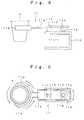
- the shaking mechanism 11 is constituted by a cup holder 11a for holding one cup A, a shaking plate 11b connected at one end to the cup holder 11a, a motor 11c for shaking the shaking plate 11b, and a base plate 11d on which the motor 11c is fixed.
- the cup holder 11a is formed of an annular member having a cutout at a position in the circumferential direction, and supports the peripheral surface of one cup A.
- the shaking plate 11b _ has an elongated hole 11e generally at a center in the longitudinal direction and is supported on the upper surface of the base plate 11d by a supporting pin 11f inserted in the elongated hole 11e.
- a rotating plate 11g is attached to the rotating shaft of the motor 11c.
- the rotating plate 11g is connected to the shaking plate 11b at the other end by an eccentric pin 11h eccentric from the rotating shaft of the motor 11c. That is, when the motor 11c is rotated in this shaking mechanism 11, the shaking plate 11b turns while being reciprocated on the supporting pin 11f by the eccentric rotation of the eccentric pin 11h, the supporting pin 11f moving along the elongated hole 11e. Circular motion of the cup A held by the cup holder 11a is thereby produced, as indicated by solid line in Fig. 5, thus shaking the cup A.
- the moving mechanism 12 is constituted by an endless belt 12a extending in the widthwise direction of the automatic vending machine body 1, and a pair of pulleys 12b disposed at two positions in the widthwise direction to rotatably support the belt 12a.
- the shaking mechanism 11 is fixed on the upper surface of the belt 12a. That is, in this moving mechanism 12, one of the pulleys 12b is rotated by a motor (not shown) to move one cup A in the widthwise direction of the automatic vending machine body 1 together with the shaking mechanism 11.
- the moving mechanism 12 moves one cup A to any of a cup carrying out position at the cup carrying mechanism 2, a material discharge position at the second material container 6, a material discharge position at the third material container 7 and a beverage preparation position.
- the nozzle 3a of the hot water supply unit 3, the nozzle 5a of the beverage extractor 5, the shooter 9a of the ice chipper 9 and the agitating member 10a of the agitation mechanism 10 are placed.
- the control unit 13 is constituted by a microcomputer and is connected to the cup carrying mechanism 2, the hot water supply unit 3, the first material container 4, the beverage extractor 5, the second material container 6, the third material container 7, the ice maker 8, the ice chipper 9, the agitation mechanism 10, the shaking mechanism 11 and the moving mechanism 12.
- the agitating member 10a of the agitation mechanism 10 is then moved downward into the cup A and shaking of the cup A is started by the shaking mechanism 11 as shown in Fig. 8. At this time, the cup A is shaken at a predetermined first speed V1 by the shaking mechanism 11. After the passage of T1 from the start of shaking, the cup A is shaken at a second speed V2 higher than the first speed V1 by the shaking mechanism 11 and agitation of the materials is started by rotating the agitating member 10a of the agitation mechanism 10. Simultaneously, a coffee solution is poured into the cup A from the nozzle 5a of the beverage extractor 5.
- a predetermined amount of ice blocks is carried out from the ice maker 8 to the ice chipper 9 and small pieces of ice are thrown into the cup A from the ice chipper 9. Even after the completion of throwing-in of small pieces of ice, shaking of the cup A and the agitation of the materials are continued while the coffee solution is being poured into the cup A. After the completion of pouring of the coffee solution, shaking of the cup A and agitation of the materials are terminated, thereby completing frappe beverage D.
- the liquid material and small pieces of ice in the cup A are agitated by the agitation mechanism 10 and the cup A is simultaneously shaken by the shaking mechanism 11.
- Mixing is performed not only by agitation of the liquid material and small pieces of ice but also by shaking of the cup A. Therefore, the liquid material and small pieces of ice can be mixed uniformly and finely with each other through the entire beverage and any parts of them are not left in an insufficiently mixed state.
- a frappe beverage can be prepared which is not inferior in terms of touch to the tongue and palate and appearance to that prepared by mixing a liquid material and crushed ice while crushing ice by a mixer as in a beverage store.
- a frappe beverage using powder materials can also be prepared and various materials can be used for preparation of a beverage.
- a frappe beverage of a coffee taste differing from ordinary hot coffee or ice coffee in terms of touch to the tongue and palate can be prepared and can be sold by this kind of automatic vending machine.
- Powder materials such as sugar and cream may be diluted with water.
- the shaking plate 11b connected at one end to the cup holder 11a is supported by the supporting pin 11f so as to be able to shake, and is shaken about the supporting pin 11f by the eccentric rotation of the rotating plate 11g connected to the shaking plate 11b at the other end, thus enabling the rotation of the motor 11c to be reliably converted into shaking motion by the simple mechanism. Therefore, this arrangement is highly advantageous in being put to practical use. Since the shaking plate 11b is caused to turn while being reciprocated in a direction along the elongated hole 11e by inserting the supporting pin 11f into the elongated hole 11e of the shaking plate 11b, the cup A can be shaken by circular motion of the cup holder 11a and mixing by shaking can be performed more effectively.
- the powder materials (sugar and cream) can be sufficiently dissolved in diluent hot water by only shaking the cup A before agitation is started, and failure to sufficiently mix the materials with small pieces of ice in a case where the materials left in powder form are mixed with ice can be avoided with reliability.
- the agitation power can be increased in comparison with the case of performing agitation only to enable a frappe beverage to be prepared in a short time.
- the cup A is shaken at the first speed V1 from the start of shaking of the cup A to the start of agitation, and is shaken at the second speed V2 higher than the first speed V1 after the start of agitation.
- Low-speed shaking ensures prevention of scattering of the liquid material when the powder materials are dissolved in diluent hot water by only shaking the cup A, and high-speed shaking enables the liquid material and small pieces of ice to be rapidly mixed with each other after throwing in of the small pieces of ice and the start of agitation.
- Small pieces of ice are intermittently supplied into the cup A while shaking of the cup A and agitation are being performed, as shown in Fig. 13. Small pieces of ice are thereby mixed efficiently with the liquid material. This method is effective in reducing the occurrence of failure to sufficiently mix the materials.
- Agitation may be started after the completion of shaking of the cup A, as shown in Fig. 14. Spilling of the beverage out of the cup A can be prevented in this way.
- This method has the advantage of maintaining the desired appearance.
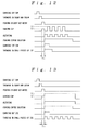
- a process may be performed in which, as shown in Fig. 15, the cup A is shaken during the passage of a predetermined first time period T1; shaking of the cup A is stopped after the passage of the first time period T1; agitation is then started; and shaking of the cup A is started after the passage of a predetermined second time period T2.
- no load due to agitation is applied to the shaking mechanism 11 when shaking is started. This method is advantageous in improving the life of the shaking mechanism 11.
- a process may be performed in which, as shown in Fig. 16, the cup A is shaken at the first speed V1 during the passage of the first time period T1; the cup A is shaken at the second speed V2 after the passage of the first time period T1; and agitation is started after the passage of the second time period T2 from the start of shaking at the second speed V2.
- a load when the shaking speed is changed is not applied to the agitation mechanism 10 when agitation is started.
- This method is advantageous in improving the durability of the agitation mechanism 10.
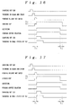
- Shaking of the cup A may be terminated after the passage of a predetermined time T3 from the termination of agitation, as shown in Fig. 17. In this way, differences in level in the surface of the completed frappe beverage can be reduced to improve the appearance.
- Agitation may be terminated after the passage of the predetermined time T3 from the termination of shaking of the cup A, as shown in Fig. 18. In this way, spilling of the beverage from the cup A can be prevented with reliability even in a case where the frappe beverage is soft (the proportion of the liquid material is large relative to that of small pieces of ice). Moreover, the grain size of ice can reduced by continuing agitation after termination of shaking to enable the liquid material and small pieces of ice to be mixed more finely.
- a frappe beverage of a fruit taste for example, can also be prepared by mixing a fruit-based liquid material and small pieces of ice.
Landscapes
- Physics & Mathematics (AREA)
- General Physics & Mathematics (AREA)
- Beverage Vending Machines With Cups, And Gas Or Electricity Vending Machines (AREA)
- Devices For Dispensing Beverages (AREA)
Abstract
Description
Claims (13)
- An automatic cup type beverage vending machine in which a liquid material and small pieces of ice are agitated in a cup (A) for containing a beverage to prepare a beverage in which the liquid material and small pieces of ice are mixed with each other, the vending machine comprising:material supply means(4,6,7) of supplying a liquid material or a powder material for forming a liquid material into the cup(A);small ice piece supply means (9) of supplying small pieces of ice into the cup(A);agitation means(10) of agitating the liquid material and small pieces of ice in the cup(A); andshaking means(11) of shaking the cup(A) in a predetermined direction at the time of preparation of the beverage.
- The automatic cup type beverage vending machine according to claim 1, wherein said shaking means (11) is constituted by a cup holder (11a) which holds the cup (A), a shaking member (11b) connected at its one end to a cup holder(11a), a supporting member (11f) which supports the shaking member (11b) so that the shaking member (11b) can shake, a rotary member (11g) connected to the shaking member (11b) at the other end, and a motor (11c) which eccentrically rotates the rotary member (11g) .
- The automatic cup type beverage vending machine according to claim 1, further comprising control means(13) of starting agitation after the passage of a predetermined time period from a start of shaking of the cup (A) .
- The automatic cup type beverage vending machine according to claim 1, further comprising control means(13) of shaking the cup(A) at a predetermined first speed during the passage of a predetermined time period and shaking the cup(A) at a predetermined second speed after the passage of the predetermined time period.
- The automatic cup type beverage vending machine according to claim 1, further comprising control means(13) of performing shaking of the cup(A) and agitation alternately and intermittently.
- The automatic cup type beverage vending machine according to claim 1, further comprising control means(13) of intermittently supplying small pieces of ice into the cup (A) while performing at least one of shaking of the cup(A) and agitation.
- The automatic cup type beverage vending machine according to claim 1, further comprising control means(13) of starting agitation after termination of shaking of the cup(A).
- The automatic cup type beverage vending machine according to claim 1, further comprising control means(13) of shaking the cup(A) during the passage of a predetermined first time period, stopping shaking the cup (A) and starting agitation after the passage of the first time period, and starting shaking the cup(A) after the passage of a predetermined second time period from the start of agitation.
- The automatic cup type beverage vending machine according to claim 1, further comprising control means(13) of shaking the cup at a predetermined first speed during the passage of a predetermined first time period, shaking the cup (A) at a predetermined second speed after the passage of the first time period, and starting agitation after the passage of a predetermined second time period from the start of shaking at the second speed.
- The automatic cup type beverage vending machine according to claim 1, further comprising control means (13) of terminating agitation after the passage of a predetermined time period from the termination of shaking of the cup(A).
- The automatic cup type beverage vending machine according to claim 1, further comprising control means (13) of terminating shaking of the cup after the passage of a predetermined time period from the termination of agitation.
- The automatic cup type beverage vending machine according to any one of claims 1, 2, 3, 4, 5, 6, 7, 8, 9, 10, and 11, wherein at least part of the liquid material is a liquid material prepared by diluting a powder material with water or diluent hot water.
- The automatic cup type beverage vending machine according to any one of claims 1, 2, 3, 4, 5, 6, 7, 8, 9, 10, 11, and 12 wherein a liquid material prepared by diluting sugar and cream with water or diluent hot water and a liquid material formed of a coffee solution are used as said liquid material.
Applications Claiming Priority (2)
| Application Number | Priority Date | Filing Date | Title |
|---|---|---|---|
| JP2004124381 | 2004-04-20 | ||
| JP2004124381A JP4149957B2 (en) | 2004-04-20 | 2004-04-20 | Cup-type beverage vending machine |
Publications (2)
| Publication Number | Publication Date |
|---|---|
| EP1589500A2 true EP1589500A2 (en) | 2005-10-26 |
| EP1589500A3 EP1589500A3 (en) | 2005-11-16 |
Family
ID=34940812
Family Applications (1)
| Application Number | Title | Priority Date | Filing Date |
|---|---|---|---|
| EP05252313A Withdrawn EP1589500A3 (en) | 2004-04-20 | 2005-04-14 | Automatic cup type beverage vending machine |
Country Status (4)
| Country | Link |
|---|---|
| US (1) | US20050242120A1 (en) |
| EP (1) | EP1589500A3 (en) |
| JP (1) | JP4149957B2 (en) |
| CA (1) | CA2503267A1 (en) |
Cited By (6)
| Publication number | Priority date | Publication date | Assignee | Title |
|---|---|---|---|---|
| EP1857027A1 (en) * | 2006-05-15 | 2007-11-21 | Thomas Petroudis | Automatic instant "frappé" coffee machine |
| ITMI20110154A1 (en) * | 2011-02-04 | 2012-08-05 | Rodolfo Poleni | AUTOMATIC DISTRIBUTOR OF FOOD AND PRODUCTS IN GENERAL |
| WO2013064663A1 (en) * | 2011-11-02 | 2013-05-10 | Fresenius Kabi Deutschland Gmbh | Device and method for preparing a fluid composition for complete or supplemental enteral nutrition |
| GR20160100598A (en) * | 2016-11-21 | 2018-08-29 | Δημητριος Ιωαννη Γκιουρος | Automatic dosimeter for liquid white and brown sugar or like liquid materials |
| CN108814306A (en) * | 2018-09-13 | 2018-11-16 | 上海丫山智能科技有限公司 | A kind of full-automatic customized taste milk tea preparer |
| TWI786040B (en) * | 2015-12-24 | 2022-12-11 | 瑞士商雀巢製品股份有限公司 | Beverage dispenser with powder container |
Families Citing this family (26)
| Publication number | Priority date | Publication date | Assignee | Title |
|---|---|---|---|---|
| JP4892950B2 (en) * | 2005-12-09 | 2012-03-07 | 富士電機リテイルシステムズ株式会社 | Beverage production equipment |
| US20080066483A1 (en) * | 2006-09-17 | 2008-03-20 | Nice Vend Ltd. | Devices and methods for producing controlled flavored ice drinks |
| US20080163643A1 (en) * | 2007-01-05 | 2008-07-10 | Strunk Jeffrey L | Beverage product and methods and devices for producing beverage products |
| US8434319B2 (en) * | 2007-09-04 | 2013-05-07 | Nicevend Ltd. | Apparatus for dispensing made to-order frozen beverage |
| US8685477B2 (en) * | 2008-01-17 | 2014-04-01 | Enodis Corporation | Method for blending a beverage in a single serving cup |
| US8857667B2 (en) * | 2008-12-08 | 2014-10-14 | Enodis Corporation | Integrated method and system for dispensing beverage ingredients |
| CA2746224C (en) * | 2008-12-08 | 2015-06-09 | Enodis Corporation | An integrated method and system for dispensing beverage ingredients |
| USD625952S1 (en) | 2009-12-08 | 2010-10-26 | Enodis Corporation | Nozzle |
| USD649984S1 (en) | 2009-12-08 | 2011-12-06 | Enodis Corporation | Ice dispenser and portion control assembly |
| JP5521593B2 (en) * | 2010-02-04 | 2014-06-18 | 富士電機株式会社 | vending machine |
| US8733121B2 (en) * | 2011-03-10 | 2014-05-27 | Richard J. Soderman | Snow cone and slushy dispenser |
| US9022081B2 (en) * | 2011-08-02 | 2015-05-05 | Baby Barista, Inc. | Apparatus and method for preparing ingredients for a baby bottle |
| EP2764306A2 (en) | 2011-10-06 | 2014-08-13 | The Delfield Company, LLC | A method and system for a beverage dispensing assembly |
| MX2015015905A (en) * | 2013-05-20 | 2016-03-09 | Manitowoc Foodservice Co Inc | Hybrid beverage dispenser. |
| CN105451615B (en) * | 2013-08-05 | 2018-02-16 | 夏普株式会社 | Stirring blades, stirring devices, beverage making devices and stirring sections |
| US10399838B2 (en) | 2014-04-30 | 2019-09-03 | The Coca-Cola Company | Dispensing system |
| EP3000779A1 (en) * | 2014-09-26 | 2016-03-30 | Anheuser-Busch InBev S.A. | Beverage dispensing device comprising at least two pod or capsule receiving means |
| USD795631S1 (en) | 2015-05-01 | 2017-08-29 | The Baby Barista Company | Apparatus for preparing ingredients for a baby bottle |
| WO2016179052A1 (en) | 2015-05-01 | 2016-11-10 | The Baby Barista Company | Apparatus and method for preparing ingredients for a baby bottle using a concentrated solution |
| CN107316389B (en) * | 2017-05-11 | 2021-01-15 | 秦皇岛维拓科技有限公司 | Vending machine based on data mining commodity inventory and dynamic pricing |
| CN107117575A (en) * | 2017-05-31 | 2017-09-01 | 杭州侬网络科技有限公司 | A kind of wine vending machine and its application method for pressing out capacity for liquor charging |
| JP7234689B2 (en) * | 2019-02-27 | 2023-03-08 | 富士電機株式会社 | beverage dispenser |
| TWI715443B (en) * | 2020-02-19 | 2021-01-01 | 迅智自動化科技股份有限公司 | Beverage brewing apparatus |
| JP7435253B2 (en) * | 2020-05-22 | 2024-02-21 | 富士電機株式会社 | cup vending machine |
| US12131671B1 (en) * | 2021-02-03 | 2024-10-29 | Zaid A. Abukhalaf | Beverage containers |
| CN113317682A (en) * | 2021-05-19 | 2021-08-31 | 齐喝彩(上海)人工智能科技有限公司 | Beverage preparing structure of automatic beverage machine |
Family Cites Families (13)
| Publication number | Priority date | Publication date | Assignee | Title |
|---|---|---|---|---|
| US1960640A (en) * | 1932-02-13 | 1934-05-29 | Roy W Lajeunesse | Beverage shaker |
| US3362692A (en) * | 1966-01-13 | 1968-01-09 | Edmund F. Iannone | Container with stirring means |
| US4590975A (en) * | 1984-06-13 | 1986-05-27 | The Coca-Cola Company | Automatic beverage dispensing system |
| ES2012391B3 (en) * | 1986-03-10 | 1990-03-16 | Solly Katz | LIQUID DISPENSER. |
| US4983412A (en) * | 1986-12-22 | 1991-01-08 | Melitta-Werke Bentz & Sohn | Method and device for producing aqueous extracts from coffee |
| US5203385A (en) * | 1992-03-31 | 1993-04-20 | Donald Waber | Apparatus and process for automatically reconstituting dry materials, especially pharmaceuticals |
| JP2989075B2 (en) * | 1992-07-01 | 1999-12-13 | 株式会社エム・シー・フーズ | Method and apparatus for extracting active ingredient from dried plant |
| US5323691A (en) * | 1992-10-09 | 1994-06-28 | Reese Joseph J | Frozen drink mixer |
| US6196712B1 (en) * | 1998-08-05 | 2001-03-06 | Elm Gunter Von | Bar having an integral cocktail mixer |
| JP2001109951A (en) * | 1999-10-08 | 2001-04-20 | Fuji Electric Co Ltd | Cup mixing beverage vending machine |
| JP2002367023A (en) * | 2001-06-08 | 2002-12-20 | Sanden Corp | Cup-type beverage vending machine |
| US6772675B2 (en) * | 2001-06-26 | 2004-08-10 | David Ervin | Apparatus for preparing frozen drinks |
| JP2003303371A (en) * | 2002-04-09 | 2003-10-24 | Fuji Electric Co Ltd | Cup-type beverage vending machine |
-
2004
- 2004-04-20 JP JP2004124381A patent/JP4149957B2/en not_active Expired - Fee Related
-
2005
- 2005-04-14 EP EP05252313A patent/EP1589500A3/en not_active Withdrawn
- 2005-04-19 CA CA002503267A patent/CA2503267A1/en not_active Abandoned
- 2005-04-19 US US11/108,896 patent/US20050242120A1/en not_active Abandoned
Cited By (9)
| Publication number | Priority date | Publication date | Assignee | Title |
|---|---|---|---|---|
| EP1857027A1 (en) * | 2006-05-15 | 2007-11-21 | Thomas Petroudis | Automatic instant "frappé" coffee machine |
| ITMI20110154A1 (en) * | 2011-02-04 | 2012-08-05 | Rodolfo Poleni | AUTOMATIC DISTRIBUTOR OF FOOD AND PRODUCTS IN GENERAL |
| EP2485196A1 (en) * | 2011-02-04 | 2012-08-08 | Rodolfo Poleni | A vending machine for foods and products in general |
| WO2013064663A1 (en) * | 2011-11-02 | 2013-05-10 | Fresenius Kabi Deutschland Gmbh | Device and method for preparing a fluid composition for complete or supplemental enteral nutrition |
| TWI786040B (en) * | 2015-12-24 | 2022-12-11 | 瑞士商雀巢製品股份有限公司 | Beverage dispenser with powder container |
| GR20160100598A (en) * | 2016-11-21 | 2018-08-29 | Δημητριος Ιωαννη Γκιουρος | Automatic dosimeter for liquid white and brown sugar or like liquid materials |
| GR1009409B (en) * | 2016-11-21 | 2018-12-04 | Δημητριος Ιωαννη Γκιουρος | Automatic dosimeter for liquid white and brown sugar or like liquid materials |
| CN108814306A (en) * | 2018-09-13 | 2018-11-16 | 上海丫山智能科技有限公司 | A kind of full-automatic customized taste milk tea preparer |
| CN108814306B (en) * | 2018-09-13 | 2020-10-30 | 嘉兴福良纺织科技有限公司 | Full-automatic self-defined taste milk tea preparer |
Also Published As
| Publication number | Publication date |
|---|---|
| JP4149957B2 (en) | 2008-09-17 |
| JP2005309679A (en) | 2005-11-04 |
| CA2503267A1 (en) | 2005-10-20 |
| US20050242120A1 (en) | 2005-11-03 |
| EP1589500A3 (en) | 2005-11-16 |
Similar Documents
| Publication | Publication Date | Title |
|---|---|---|
| US20050242120A1 (en) | Automatic cup type beverage vending machine | |
| EP2232172B1 (en) | Method for blending a beverage in a single serving cup | |
| CA2313608C (en) | Method and apparatus for controlling the blending of drinks | |
| EP1264567A2 (en) | Cup beverage vending machine | |
| US20150109879A1 (en) | Method and apparatus for making food products | |
| RU2529213C2 (en) | Device for dosaged dispensing of ordered frozen beverages | |
| WO2008032306A2 (en) | Devices and methods for producing controlled flavored ice drinks | |
| CN105321263A (en) | Beverage mixing method inside cup | |
| EP2215940B1 (en) | Ice cube metering device | |
| JP4224858B2 (en) | Beverage blending method of beverage vending machine and beverage vending machine | |
| TWI272367B (en) | Ice shaver/blender control apparatus and method | |
| JP2002352315A (en) | Cup vending machine | |
| JP2010160692A (en) | Cup type vending machine | |
| JP2012059096A (en) | Cup type automatic vending machine | |
| JPH0231081Y2 (en) | ||
| CN113706779B (en) | Cup type vending machine | |
| JP3925346B2 (en) | Effervescent beverage cooking method and effervescent beverage cooking apparatus of cup type vending machine | |
| KR200238056Y1 (en) | Raw material mixing device of vending machine | |
| JP3885761B2 (en) | Cup-type beverage vending machine | |
| JP4510986B2 (en) | vending machine | |
| JP3234863B2 (en) | Cup-type beverage vending machine | |
| JP2007286916A (en) | Cup type frozen beverage cooking vending machine | |
| JP2002260088A (en) | Cup vending machine | |
| JP4136596B2 (en) | Cup-type beverage vending machine | |
| WO2020003466A1 (en) | Apparatus for producing hot or frozen or ice beverages |
Legal Events
| Date | Code | Title | Description |
|---|---|---|---|
| PUAI | Public reference made under article 153(3) epc to a published international application that has entered the european phase |
Free format text: ORIGINAL CODE: 0009012 |
|
| PUAL | Search report despatched |
Free format text: ORIGINAL CODE: 0009013 |
|
| AK | Designated contracting states |
Kind code of ref document: A2 Designated state(s): AT BE BG CH CY CZ DE DK EE ES FI FR GB GR HU IE IS IT LI LT LU MC NL PL PT RO SE SI SK TR |
|
| AX | Request for extension of the european patent |
Extension state: AL BA HR LV MK YU |
|
| AK | Designated contracting states |
Kind code of ref document: A3 Designated state(s): AT BE BG CH CY CZ DE DK EE ES FI FR GB GR HU IE IS IT LI LT LU MC NL PL PT RO SE SI SK TR |
|
| AX | Request for extension of the european patent |
Extension state: AL BA HR LV MK YU |
|
| RIC1 | Information provided on ipc code assigned before grant |
Ipc: 7G 07F 13/10 B Ipc: 7G 07F 13/06 A |
|
| AKX | Designation fees paid | ||
| REG | Reference to a national code |
Ref country code: DE Ref legal event code: 8566 |
|
| STAA | Information on the status of an ep patent application or granted ep patent |
Free format text: STATUS: THE APPLICATION IS DEEMED TO BE WITHDRAWN |
|
| 18D | Application deemed to be withdrawn |
Effective date: 20060517 |