EP1589347A1 - Système de résonateur haute fréquence avec une distribution de courant optimisée dans les éléments conducteurs - Google Patents
Système de résonateur haute fréquence avec une distribution de courant optimisée dans les éléments conducteurs Download PDFInfo
- Publication number
- EP1589347A1 EP1589347A1 EP05008331A EP05008331A EP1589347A1 EP 1589347 A1 EP1589347 A1 EP 1589347A1 EP 05008331 A EP05008331 A EP 05008331A EP 05008331 A EP05008331 A EP 05008331A EP 1589347 A1 EP1589347 A1 EP 1589347A1
- Authority
- EP
- European Patent Office
- Prior art keywords
- conductor elements
- resonator
- conductor
- elements
- resonator system
- Prior art date
- Legal status (The legal status is an assumption and is not a legal conclusion. Google has not performed a legal analysis and makes no representation as to the accuracy of the status listed.)
- Granted
Links
Images






Classifications
-
- G—PHYSICS
- G01—MEASURING; TESTING
- G01R—MEASURING ELECTRIC VARIABLES; MEASURING MAGNETIC VARIABLES
- G01R33/00—Arrangements or instruments for measuring magnetic variables
- G01R33/20—Arrangements or instruments for measuring magnetic variables involving magnetic resonance
- G01R33/28—Details of apparatus provided for in groups G01R33/44 - G01R33/64
- G01R33/32—Excitation or detection systems, e.g. using radio frequency signals
- G01R33/34—Constructional details, e.g. resonators, specially adapted to MR
- G01R33/34046—Volume type coils, e.g. bird-cage coils; Quadrature bird-cage coils; Circularly polarised coils
- G01R33/34061—Helmholtz coils
-
- G—PHYSICS
- G01—MEASURING; TESTING
- G01R—MEASURING ELECTRIC VARIABLES; MEASURING MAGNETIC VARIABLES
- G01R33/00—Arrangements or instruments for measuring magnetic variables
- G01R33/20—Arrangements or instruments for measuring magnetic variables involving magnetic resonance
- G01R33/28—Details of apparatus provided for in groups G01R33/44 - G01R33/64
- G01R33/32—Excitation or detection systems, e.g. using radio frequency signals
- G01R33/34—Constructional details, e.g. resonators, specially adapted to MR
- G01R33/34046—Volume type coils, e.g. bird-cage coils; Quadrature bird-cage coils; Circularly polarised coils
- G01R33/34076—Birdcage coils
-
- G—PHYSICS
- G01—MEASURING; TESTING
- G01R—MEASURING ELECTRIC VARIABLES; MEASURING MAGNETIC VARIABLES
- G01R33/00—Arrangements or instruments for measuring magnetic variables
- G01R33/20—Arrangements or instruments for measuring magnetic variables involving magnetic resonance
- G01R33/28—Details of apparatus provided for in groups G01R33/44 - G01R33/64
- G01R33/32—Excitation or detection systems, e.g. using radio frequency signals
- G01R33/34—Constructional details, e.g. resonators, specially adapted to MR
- G01R33/341—Constructional details, e.g. resonators, specially adapted to MR comprising surface coils
-
- G—PHYSICS
- G01—MEASURING; TESTING
- G01R—MEASURING ELECTRIC VARIABLES; MEASURING MAGNETIC VARIABLES
- G01R33/00—Arrangements or instruments for measuring magnetic variables
- G01R33/20—Arrangements or instruments for measuring magnetic variables involving magnetic resonance
- G01R33/28—Details of apparatus provided for in groups G01R33/44 - G01R33/64
- G01R33/32—Excitation or detection systems, e.g. using radio frequency signals
- G01R33/34—Constructional details, e.g. resonators, specially adapted to MR
- G01R33/34007—Manufacture of RF coils, e.g. using printed circuit board technology; additional hardware for providing mechanical support to the RF coil assembly or to part thereof, e.g. a support for moving the coil assembly relative to the remainder of the MR system
-
- G—PHYSICS
- G01—MEASURING; TESTING
- G01R—MEASURING ELECTRIC VARIABLES; MEASURING MAGNETIC VARIABLES
- G01R33/00—Arrangements or instruments for measuring magnetic variables
- G01R33/20—Arrangements or instruments for measuring magnetic variables involving magnetic resonance
- G01R33/28—Details of apparatus provided for in groups G01R33/44 - G01R33/64
- G01R33/32—Excitation or detection systems, e.g. using radio frequency signals
- G01R33/34—Constructional details, e.g. resonators, specially adapted to MR
- G01R33/34015—Temperature-controlled RF coils
- G01R33/34023—Superconducting RF coils
-
- G—PHYSICS
- G01—MEASURING; TESTING
- G01R—MEASURING ELECTRIC VARIABLES; MEASURING MAGNETIC VARIABLES
- G01R33/00—Arrangements or instruments for measuring magnetic variables
- G01R33/20—Arrangements or instruments for measuring magnetic variables involving magnetic resonance
- G01R33/28—Details of apparatus provided for in groups G01R33/44 - G01R33/64
- G01R33/32—Excitation or detection systems, e.g. using radio frequency signals
- G01R33/34—Constructional details, e.g. resonators, specially adapted to MR
- G01R33/34092—RF coils specially adapted for NMR spectrometers
Definitions
- HF high-frequency
- NMR nuclear magnetic resonance
- High-frequency resonator systems of this type are for example made US Pat. No. 5,276,398, corresponding to Reference Literature [8].
- NMR nuclear magnetic resonance
- An RF resonator system consists of a or more RF resonators.
- the at least one RF resonator is for the NMR measurement placed in close proximity to the sample.
- the RF resonator system is galvanic, capacitive or inductive to a transmitting or Receiving electronics coupled to the NMR apparatus.
- Each RF resonator typically includes several uninterrupted ones Conductor elements that are electromagnetically coupled to each other, that is a current flow in one of the conductor elements is due to electromagnetic coupling with a current flow in the rest Ladder elements associated.
- the entirety of the conductor elements represents an RF resonant circuit whose resonance frequency corresponds to the NMR experiment (in particular the static magnetic field strength) is adjusted.
- HTS high-temperature superconductor
- the basis of the present invention is, in an RF resonator, the Adjust current distribution in the individual conductor elements by the Couplings between the individual conductor elements of the RF resonator be selected specifically.
- the couplings can in particular by choice of Length of overlapping conductor sections, by lengthening of Ladder elements about meandering sections, by changing the distance of conductor elements and / or by changing the Cross section of conductor elements can be adjusted.
- a simulation program can be used, which solves the Maxwell equations and then iteratively solves the geometry changed the conductor elements.
- prior art RF resonator systems only take into account the setting of the desired resonant frequency of an entire RF resonator or RF resonator system. This leads to strong relative differences in the current densities in the various conductor elements during operation. Conductor elements with a high relative current density quickly reach the region of their limiting current density at high RF magnetic field strengths.
- the limiting current density can be given by the critical current density j c in the case of a superconducting conductor element, or by a transition to non-linear resistance, or by a melting temperature achieved by cooling by ohmic heating or diffusion activation in a normal conducting conductor element.
- this conductor element in the RF resonator typically fails, and the coupling behavior in the RF resonator changes.
- the resonant frequency of the RF resonator is generally detuned, and eventually the RF resonator is irreversibly destroyed.
- Most conductor elements remain well below their respective limiting current density.
- configured RF resonators have one of two Power distribution variants on.
- desired current distribution has a desired maximum current, approximately at the maximum a sine at ⁇ / 2.
- the conductor elements are now so designed so that the current flow is greater in any conductor element than in the setpoint current maximum.
- a "quasi-steady" or smooth Power distribution can be adjusted with respect to adjacent conductor elements. This is achieved, for example, by reducing the capacitive coupling between the affected marginal conductor elements and the ring of Birdcage resonator and thus achieved a lower current injection.
- the full current carrying capacity of Conductor elements are used in the range of the desired maximum current.
- the maximum value of the quotient values of each conductor element is less than or equal to the maximum value in that one Conductor element with the largest according to the target power distribution maximum value of Quotient values of this conductor element.
- a conductor element In a conductor element is in operation at a first location (with respect to z, coordinate along the conductor element) a first Cross section considered. Vertically through this cross-section flows spatially distributes electricity, i. spatially different, local current densities exist j (x, y) (with x, y: coordinates perpendicular to z). For the determination of Current densities are each the maximum amplitude of the considered Based on alternating current, i. the temporal evolution of the considered AC within a period is disregarded calmly. Now the local current densities become over the cross-sectional area integrated and thus determines an average current density in the cross section.
- a local limiting current density At the location (with respect to z) of the cross section is given a local limiting current density.
- a location dependence of the limiting current density along z can be, for example due to anisotropy with respect to the static magnetic field a result in a curved conductor element.
- the quotient of average current density and limiting current density gives the quotient value at the location of the cross section.
- the highest quotient value is called the Maximum value of the quotient values of the conductor element. Usually becomes the highest quotient value in the area of a center of symmetry, especially in the middle of a ladder element, found.
- all the conductor elements have an identical one Cross section and a uniform, spatially constant limiting current density; then the maximum values of the quotient values in the ladder elements are proportional the maximum currents in the conductor elements.
- the maximum values of the Quotient values are essentially the same in particular when the Deviation of each maximum value from the mean value of the maximum values of individual conductor elements a maximum of 25%, preferably at most 10%.
- the maximum values of the quotient values along the individual conductor elements are furthermore according to the invention essentially the same in particular then, if the mean of the maximum values of the quotient values is at least 75%, preferably at least 90%, of the maximum value of the quotient values of the conductor element with the largest maximum value of the quotient values of all conductor elements. In this case, the total current carrying capacity of the RF resonator system to at least 75% or 90% utilized.
- the conductor elements are made of superconducting material, in particular NbTi or Nb 3 Sn.
- superconducting conductor elements can carry HF currents with low loss, so that the RF resonator system can achieve particularly high resonator qualities and NMR signals with high signal can be detected as noise behavior.
- An advantageous embodiment provides that the conductor elements on a plane, polyhedral or cylindrical, dielectric substrate are applied.
- the substrate mechanically stabilizes the associated one Resonator, and as a dielectric, the coupling of the conductor elements influence.
- the substrate allows the dissipation of heat, especially with normal conductive conductor elements, or the Cooling of superconducting conductor elements below the transition temperature of superconducting material.
- a substrate can according to the invention on top and Bottom be provided with ladder elements. Also, two substrates, the each having conductor elements, attached to each other and / or each other be glued.
- the conductor elements approximately have rectangular cross-section, in particular with a thickness between 200 nm and 1 ⁇ m and / or a width between 2 ⁇ m and 50 ⁇ m.
- the rectangular cross-section is easy to manufacture and the computer-aided Determination of geometries according to the invention for conductor elements is included This basic form is particularly simple.
- the limiting current densities are particularly advantageous all conductor elements of an RF resonator equal. This can for example, by a suitable, uniform, isotropic material for all conductor elements are achieved.
- the conductor elements of a RF resonator at the location of their respective maximum quotient values respectively have identical cross sections.
- the average current density in each conductor element proportional to the local current flow which in turn determines the determination of inventive geometry of conductor elements is facilitated.
- Ladder elements have a meandering section, in particular wherein the meandering section in the area of the base of a U-shaped Conductor element is arranged.
- Meandering sections allow the targeted, predominantly changing the inductance of an individual Conductor element, or the standing wave properties and thus its resonance frequency.
- conductor pairs are formed by adjacently arranged conductor elements.
- capacitive coupling between These ladder elements can be adjusted specifically.
- Such an overlap can also be formed in the two end regions of a single conductor element be distributed (Fig. 1 a E), or over the entire length of an element ( Figure 1a: F and G).
- Ratio between the width of the conductor element and the distance to adjacent conductor elements in the area of overlaps for various Conductor pairs is different. Width and spacing of the conductor elements can also independently of each other with different conductor pairs be set differently according to the invention. These geometries allow a targeted adjustment of the coupling between the conductor elements.
- an RF resonator system is further characterized in that the RF resonator comprises four sets of nested U-shaped conductor elements, wherein the U-shaped conductor elements of each set are opened in a same direction toward the center of the RF resonator, that within each set with more outer U-shaped conductor elements, the ends of the legs relative to the ends of the legs of further inwardly disposed U-shaped conductor elements are reset to show that two sets with the opening directions of their U-shaped conductor elements to each other and in one Level are arranged the U-shaped ladder elements of the two sets of each plane do not interfere with each other, and wherein the opening directions of the U-shaped conductor elements of the first plane are rotated by 90 ° with respect to the opening directions of the U-shaped conductor elements of the second plane.
- This RF resonator system has substantially equal maximum values of the quotient values for all the conductor elements.
- the two levels are arranged parallel adjacent and by a dielectric layer interconnected.
- an RF resonator system which provides that the RF resonator comprises two sets of U-shaped conductor elements, wherein the U-shaped conductor elements of each set are in each case nested and opened in a same direction, that the opening directions of the U-shaped ladder elements of the two sets face each other, that the legs of the U-shaped conductor elements of the two sets interlock, wherein in each space between two adjacent legs of conductor elements of a set engages exactly one leg of a conductor element of the other set, and that the depth of engagement of the legs of the U-shaped conductor elements in the spaces in the RF resonator in an inner region adjacent to the window decreases from inside to outside.
- This RF resonator system also has substantially the same maximum values of the quotient values for all the conductor elements.
- this RF resonator system increases the depth of engagement the legs of the U-shaped conductor elements in the interstices in the RF resonator in an outer area from the inside out again too.
- the current carrying capacity in the outer region is better in the Resonator involved, especially in the case of many conductor elements depending Set.
- an embodiment of an inventive RF resonator system which several identical RF resonators, in particular 2 or 4 identical HF resonators comprises.
- These Embodiment can be used as a simple, planar Helmholzan extract which has particularly good field homogeneity with respect to B1.
- an RF resonator system which provides that the RF resonator comprises at least one set of straight, parallel conductor elements, in a middle area of the set, the conductor elements are each of equal length, and that in outer areas of the set further outside conductor elements are shortened in relation to further inside conductor elements.
- peak-shaped current peaks in the outer conductor elements ie in the edge region of the set, are eliminated.
- a typical set is a pole of a birdcage resonator. Such a set also represents a package of ladder elements in the sense of the invention.
- An embodiment of this RF resonator system is characterized in that that the RF resonator system as birdcage resonator, in particular hybrid birdcage resonator is formed and several sets of straight, parallel Includes conductor elements. In this case, current overshoots at each Outside of each set is eliminated, and the birdcage resonator is in its performance by the current flow of the conductor element or the Conductor elements determined at the maximum of its sinusoidal current distribution.
- a RF resonator system wherein the RF resonator system Part of an NMR probe head and having a sample to be measured, wherein the ladder elements on one or more level, polyhedral or cylindrical, dielectric substrates are placed and the spatial Arrangement of the conductor elements is selected so that in the active volume of Sample generated RF magnetic field is as homogeneous as possible.
- the computer-aided calculation can This is done by first setting the conditions for the simplest Case identical current flow in each conductor element set and recorded be, with all conductor elements should have the same cross-section.
- the conductor elements are placed on the substrates in such a way that under the condition of equal maximum currents in all conductor elements one maximum field homogeneity is achieved.
- the (especially capacitive) couplings between the elements so set that in operation also really essentially the same size Maximum currents flow in the conductor elements. Is this capacitive Current transfer located between conductor elements, then its influence on the field homogeneity negligible. Otherwise, it must be an iterative process to go through. Regularly is to homogenize the field outside more current flow than required inside, so that the conductor density in RF resonators is enlarged according to the invention according to the outside.
- the galvanic connection may be preferred Symmetry points of the conductor elements take place.
- the connection points can continue to be coupled into or out of an RF resonator be used.
- An embodiment provides that all the conductor elements a rectangular cross section with uniform width and uniform height have width and height perpendicular to the main flow direction of the Ladder elements run. This embodiment is particularly simple produce and calculate.
- a preferred embodiment, in particular for RF resonator systems superconductor, contains platelets that carry little or no current. These In particular, platelets can be placed so that they are macroscopic homogeneous distribution of the conductor material is achieved.
- the RF resonator has at least 10 conductor elements, preferably has at least 20 conductor elements.
- the RF resonator has at least 10 conductor elements, preferably has at least 20 conductor elements.
- a particularly high performance of the RF resonator system be achieved.
- An embodiment in which the conductor elements are at least preferred is also preferred have partially different natural resonances.
- the Arrangement of the conductor elements are designed to be particularly free.
- the conductor elements of RF resonator are only nested in one another.
- the Ladder elements not nested. Nested inside means that further inside conductor elements completely within a range lie, outline the more outer conductor elements. In other words a sequence of conductor elements in the resonator follows from the inside outside, for example, from a window away.
- nesting is a portion of a first conductor element between two sections of a second conductor element, wherein the two sections of the second Conductor element in the resonator on the one hand on the outside and on the other hand on inside lie as the portion of the first conductor element.
- the mesh Nesting makes it easier to adjust the setting compared to nesting Current distribution in the conductor elements and thus in the resonator.
- an embodiment is preferred that by is characterized in that the conductor elements exclusively from the linear Basic type and / or U-shaped basic type and / or open-ring Basic type are.
- These basic types are particularly easy to manufacture and in to integrate an inventive RF resonator system. It can the ladder elements of said basic types are variations such as meandering Have sections.
- the RF resonator of an RF resonator system according to the invention free of To design ladder elements of the spiral basic type.
- sample heads are currently either Helmholz- / Birdcagespulen of normal metal or when using superconducting material planar Helmholz coils or hybrid birdcage resonators in use.
- Each of these resonator types may be described as composed of a number N ( N ⁇ 1) of conductor elements i .
- a conductor element here a coherent piece of conductor track is defined, which itself can also be understood as a resonator.
- Each of these conductor elements has a certain resonant frequency f i , which is given by the distributed capacitances (eg with elements of the type E) and inductances or with missing or very low capacitive coupling between the two end regions of the element (eg with elements of the type A, B , C, D but also F and G) through the standing wave along the length of the element.
- basic elements straight line A, U-shaped B, open rings C, D and spiral F are used.
- a basic type recognized in the context of the invention is the meander G.
- the basic elements can be assembled as shown by way of example in FIG. 1b, for example (B + B) or (2A + 2B) or (E + E) etc.
- the composition of the Conductor elements with a single boundary condition the fundamental frequency of the resulting resonator should be targeted.
- a superconductor carries current only up to the critical current density j c with low resistance.
- NMR coils are designed to generate transverse B fields of maximum strength to allow the shortest possible pulses. It is therefore important to have the maximum possible current in the resonator, which means that all the conductor elements should carry the same maximum current (this applies, however, under the simplifying assumption of the same current carrying capacity of all the conductor elements, given different current carrying capacities in different conductor elements, see above) the quotient of the maximum current in the conductor element and the current carrying capacity of the conductor element should be essentially the same for all the conductor elements If even the current carrying capacities along a single conductor element are variable, then the maximum values of the quotient values must be taken into account, see above).
- the superconductor will quench locally. This tends to detune the resonant frequency of the overall resonator and significantly degrade RF matching, thereby making it impossible to induce higher currents in the resonator. This can occur even at currents significantly below a quench, when the RF resistance of the superconductor begins to increase (nonlinear IU characteristic / resistance characteristic of the superconductor). In this case, the current density, above which non-linearities occur, should be understood as the limiting current density.
- the shutdown to the maximum current in the conductor element takes place in view that within a conductor element current maxima and Alternate voltage maxima of different strength; for the determination of the maximum possible current in a conductor element is the global one Use current maximum in the conductor element (Varies the current carrying capacity also along a conductor element, then the maximum quotient value is off Current, i. average current density, and current carrying capacity, i. Limiting current density, to be used for each conductor element and to an im To set substantially the same value, cf. again above).
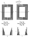
- FIG. 2a Illustrated by way of example in FIG. 2a is a distributed capacitance resonator composed of a plurality of resonators (conductor elements) 21 of type C of FIG. 1a.
- Fig. 2b shows the current flowing through the individual conductor elements maximum current, as it is present in the sectional plane II-II 'of Fig. 2a.
- each finger 22 is still divided into "fingers" 23a-23c, cf. Fig. 3a, flows mainly current on the two outermost of the fingers of a finger, cf. Fig. 3b , and the current distribution in a section through the resonator (for reasons of simplicity cuts are always on an axis of symmetry, where maximum currents occur) has a strong maximum towards the outside. At the same time, the maximum current that can be carried by the resonator decreases relative to the embodiment of FIG. 2a.
- the fingers of a finger are understood to be similar, parallel aligned, adjacent conductor elements; the whole of these little fingers is called a finger.
- FIGS. 4a and 4b show top and bottom sides of a substrate coated on both sides with HTS material (or two substrates which are stacked on one another by means of a dielectric). The flow of current again takes place predominantly in the outer area ( FIG. 4c ); the inner conductor elements are not utilized.
- the invention is now in its first variant, by adjusting the Conductor elements and their couplings so the power through the resonator distribute that the current distribution is homogeneous, d. H. the maximum current in Each conductor element is the same size, and possibly also that the Current distribution in the resonator is defined so that the generated thereby magnetic field B1 is as homogeneous as possible.
- a combination of the two Solutions is an equal distribution of maximum currents in a geometric Distribution of the conductor elements, the homogeneity of the generated RF field optimized in the range of the NMR sample.
- the current distribution can be adjusted as desired by the Natural frequencies of the individual resonators (by adjusting the Standing wave characteristics or the inductances and capacitive coupling between the end regions of the conductor elements) and the capacitive and inductive couplings between the individual resonators are adjusted. It should be shown by these methods in particular that (preferred) in which mainly the capacitive couplings are changed around the Current e.g. distribute homogeneously.
- FIGS. 5a and 6a each show RF resonators based on nested U-shaped conductor elements.
- the embodiment according to the invention of a resonator according to FIG. 5a has two sets 51, 52 of U-shaped conductor elements.
- the conductor elements of a respective set 51, 52 are aligned in parallel.
- the legs of the ladder elements of the two sets 51, 52 face each other and engage each other so that one leg of the one set engages between two legs of the other set, with exceptions at the inner and outer edges.
- a portion of the conductor elements, namely the conductor elements 54 and 58 at the inner edge of the resonator, define a window 57 located in the center of the resonator.
- the limb lengths of the conductor elements having certain lengths are selected in order to level the current flow in the conductor elements.
- the respective maximum currents occur in the plane of symmetry VI-VI '.
- the associated current distribution, cf. Fig. 6b shows a maximum at the second outermost conductor element and a large decrease in the maximum currents towards the inner conductor elements.
- the innermost conductor element shows approximately a current value of 40% of the maximum current value of the second outermost conductor element.
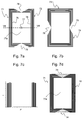
- the resonator according to the invention consists of four sets 71-74 of within a set of parallel aligned U-shaped conductor elements, said sets 71, 72 on the top of a substrate in a first plane and the sets 73, 74 on the underside of Substrate are arranged on a second level.
- the legs of the ladder elements of the two sets of a plane point towards each other.
- the opening directions of the legs of the conductor elements of the top and bottom are rotated against each other by 90 °.
- the innermost conductor elements 75, 76 surround and define in a rectangular manner a window 77a of the resonator, shown by way of example for the top side in FIG. 7a.
- the sample to be measured is to be arranged.
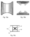
- the sample is preferably arranged in the center of the space between the at least two resonators in the region of the window (see FIG. 15c).
- triangular free spaces 78, 79 remain between the ends of the opposite legs of the conductor elements of a plane. In this case, the ends of legs located farther out are further spaced in the leg direction than ends of thighs lying further inwards.
- the current distribution in the plane of symmetry VII-VII ', where the maximum currents occur, is shown in Fig. 7c .
- FIG. 7d to illustrate the area of the window 77a, an overlay of the sets 71 to 74 in the substrate plane is shown.
- the sets 73, 74 of conductor elements of the underside are shown in dashed lines and are largely covered by the sets 71, 72 of the top.
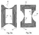
- FIGS. 9a, 9b An embodiment of an inventive RF resonator according to FIGS. 7a, 7b, but with significantly more conductor elements, is shown in FIGS. 9a, 9b .
- the maximum currents are essentially the same in all tracks here.
- a ladder element is shortened in each case in order to cut the "tip-shaped current increase", comparable to the birdcage, see below. Affected is the innermost, adjacent to the window conductor element 91, 92 and the outermost conductor element 93, 94. In even more elements, more than one conductor element can be shortened.
- the free spaces 95, 96 here are roughly U-shaped or semicircular.
- any kinks in Conductor elements approximately at right angles to each other Ladder sections of a conductor element to be rounded.
- sections of ladder elements can be rounded by replaced sections.
- a resonator or resonator system is initially arbitrary, e.g. according to Fig. 8a / 8b, designed. Then the current distribution for the relevant resonance mode calculated. From this the corrections for the determined capacitive couplings. That the difference between one Reference value and the actual maximum current density is determined and the capacitances of the conductor elements with too low currents proportional to this difference increases, which decreases accordingly with too high currents (In case of unequal conductor cross sections or different Limit current densities will be the quotient values and not the Absolute values of the currents used in the adaptation). Should be a homogeneous Power distribution can be achieved, then this reference value for all Conductor elements the same.
- each conductor element in the Rand Scheme be assigned a reference value that is smaller than the global Maximum value (set current maximum) of the remaining conductor elements is.
- the Reference values can be chosen so that any power distribution can be adjusted, in particular the desired current distribution, the maximum Field homogeneity achieved for a given resonator system. In the Adaptation of the electromagnetic couplings and natural resonances of the Care should be taken to ensure that the resonant frequency of the considered resonant mode remains at the correct frequency. This will be in Case of homogeneous current distribution approximately achieved when, as Reference value for adjusting the current densities of the mean of the Maximum currents is used. Finally, the power distribution is again calculated. It usually takes less than five iterations to complete Conductor elements less than 5% deviations from the average current and adjust the resonant frequency. When adjusting the inductors applies the procedure, of course, as well.
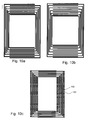
- the capacitive couplings between the conductor elements can be changed either by changing the length of the fingers in the finger capacitors (compare FIGS. 5a, 5b, 7a, 7b) or by changing the width the finger at the same distance (see Fig. 10a ) or the distance at the same finger width (see Fig. 10b ) or be adapted by any combination of these three options.
- the current distribution can also be homogenized or adjusted as desired by adjusting the inductances of the individual printed conductors.
- An increase in the inductance can be achieved, for example, by increasing individual loops.
- a further possibility for increasing the inductance can be achieved by local meanders (ie meandering sections 101, 102) either within the finger capacitors or outside, cf. Fig. 10c , the finger capacitors or a combination of the two.
- connection points are, for example, locations with the same electrical potential during operation of the resonator. Such locations of equal electrical potential are regularly found on planes of symmetry of resonators. If the currents are homogenized in a resonator and a galvanic connection of the elements is carried out at locations of the same potential, then the current distribution changes only insignificantly (depending on the width of the connection).
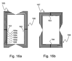
- the resonator of FIGS. 7a, 7b may have four connecting elements 161-164 in each case in the middle of the sets 165-168, as shown in FIGS. 16a and 16b .
- the connecting element 161 connects the six pairs of adjacent conductor elements 169a-169f.
- FIGS. 11 a and 11 b Further embodiments with galvanic connections of individual Elements are shown in FIGS. 11 a and 11 b. In these Connections are not connections in planes of symmetry, causing the distribution of currents substantially different from the galvanic coupling depends. The capacitances and inductances of the conductor elements as well as their Couplings with other elements must in this case under the Framework condition of a galvanic coupling to be adjusted.
- the conductor element 111 b is U-shaped, while the conductor elements 111 a, 111 c and 111 d are U-shaped with meander structures on the base.
- the meander structures serve to adapt the current in the conductor elements 111a-111d.
- Meander structures may in principle also be provided alternatively or additionally on the legs.
- the left side legs of the conductor elements 111 a - 111 d are connected at their ends to a first connecting element 112, and the right side legs are connected at their ends to a second connecting element 113.
- the resonant frequency of this resonator is adjusted by a fixed or variable capacitance 114 in the form of a chip or trimmer between the terminal legs 112, 113.
- the current distribution is largely homogeneous over a wide frequency range.
- Fig. 11b shows a resonator according to the invention with a total of 24 conductor elements.
- the sets 115a and 115b of conductor elements are connected to a connection element 116 at the ends of the conductor elements; the set 115c is connected to a connecting element 117, and the set 115d is connected to a connecting element 118.
- a capacitance 119 embodied as a chip or trimmer is also installed in order to be able to set the resonant frequency of the resonator.
- the homogenization of the currents over a certain range of the capacity 119 works.
- the adaptation of the currents in the individual legs is done by capacitive adjustment.
- the lengths were adjusted only for the sake of simplifying the simulation calculation, instead of adjusting the ratio of track width to track distance.
- the sets of ladder elements on the left, 115a / c, and right, 115b / d, were interconnected at the top and bottom. This does not have to be this way. It can also be interconnected only at the terminal leg of the capacitor 119 by means of the connecting elements 117, 118 and the tracks above can be continued without galvanic connection. In this case, however, the couplings between the conductor elements must be readjusted.
- the invention can also be applied to other coil types: e.g. on the Hybrid coil according to [9].
- FIG. 12a shows by way of example a hybrid birdcage resonator in a perspective view.
- This resonator has a total of six bars, of which three bars 121 c, 121 d, 121 e in Fig. 12a are visible.
- the rods each consist of several straight, parallel aligned conductor elements.
- the individual conductor elements of the rods 121c-121e are not shown individually in FIG. 12a, but only their area is marked.
- the bars 121c-121e are overlapped by two metal foils 123.
- FIG. 12b shows a sectional view along the plane XII-XII 'of FIG. 12a.
- the six bars 121a-121f and two windows 124 are all arranged regularly around the center of the hybrid birdcage resonator.
- the arrow 122 shows the representation direction of a location coordinate P in FIGS. 13b / 14b, in which the distribution of the amplitudes of the maximum alternating currents in the conductor elements during operation of a birdcage resonator (FIG. 13b) according to the invention and a birdcage resonator according to the prior art (FIG. Fig. 14b) is shown.
- the gaps 124a between adjacent rods 121a-121f may also be considered as further small windows.
- the bars are described in more detail in FIGS. 13a / b for the birdcage resonator according to the invention and 14a / b for a birdcage resonator of the prior art.
- the bars 136, 146 consist of a plurality of straight, approximately in-plane, parallel aligned conductor elements 131, 132a, 132b, 141 (The illustration of the conductor elements 131, 132a, 132b, 141 is interrupted in the middle, for clarity increase).
- the conductor elements 131, 132a, 132b, 141 are continued above and below with galvanically isolated plates 138a, 145 in order to minimize the magnetization effects [9, 10]).
- the conductor elements 131, 132a, 132b, 141 are made of HTS material and are here applied to a substrate, which also serves as a dielectric.
- the conductor elements are located in Fig. 12b on the inside of the rods 121a-121f, so that no galvanic contact of the conductor elements with the metal foil 123 is formed.
- the conductor elements 141 have an identical length and are overlapped at the ends by metal foils 123 spaced by a dielectric, thereby forming capacitances that are identical for all the conductor elements 141.
- galvanically isolated plates 145 are arranged, which cause a macroscopically homogeneous distribution of superconductor material according to [10].
- a plurality of rods 146 which are assembled by metal foil 123 or metallic ring, form a hybrid birdcage resonator.
- FIG. 14b shows the currents in four bars 146a-146d symmetrical to one of the windows 124 for the case of the six-bar birdcage resonator.
- the location coordinate P corresponds to the arrow 122 in FIG. 12b; the outer rods 146a, 146d in FIG. 14b, corresponding to 121a, 121d in FIG. 12b, are shown only in half.
- the current at the edges of the rods 146a-146d is much higher than the center of the rods 146a-146d.
- the current strength is above the current intensity of the maxima 144a, 144b of the sinusoidal current distribution in the resonator.
- Further current peaks having a lower amplitude than those of the maxima 144a, 144b are present at the positions 143e and 143f.
- each rod is divided into many conductor elements 131, 132a, 132b; the rod 136 thus forms a set of ladder elements.
- the conductor elements 131, 132a, 132b are overlapped by metal foils 123 spaced apart by dielectrics.
- galvanically isolated plates 138a are provided for macroscopic homogenization of the superconductor material, cf. [10].
- the capacitance formed between the individual conductor elements 131, 132a, 132b and the metal foil 123 is here adapted so that the current distribution is globally sinusoidal, ie the peak-shaped current peaks are eliminated. This also leads to improved homogeneity of the B1 field.
- the adaptation takes place in this example via a shortening of the outer, ie marginal conductor elements 132a, 132b with respect to the further inner conductor elements 131, which have a uniform length. The shortening is more pronounced in the further outward conductor elements 132a than in the further inner conductor elements 132b. In the case shown, only the respective two outer conductor elements 132a, 132b are shortened.
- the width of the conductor elements 131, 132a, 132b can also be changed, as can the layer thickness or the material of the capacitance-forming dielectric.
- the current maxima 133 occurring at the edge positions of the bars are attenuated, cf. the current distribution in Fig. 13b on the four bars 136a-136d (corresponding to 121a-121d in Fig. 12b) symmetrical to one of the two large windows 124 of a birdcage resonator according to the invention with a total of six bars.
- the amounts of the current maxima 133 are smaller than the amounts of the current intensities of the maxima 134a, 134b of the sinusoidal desired current distribution.
- the current across all traces of a Birdcage resonators (on each pole or on all poles) evenly distributed be set, which would lead to the highest current carrying capacity but would reduce the B1 homogeneity of the coil.
- FIG. 15c An array of resonators as shown in Fig. 15c can be easily equipped with improved field homogeneity.
- the resonator pairs 151, 152 and 153, which are arranged around the sample 154 to be measured, can then be designed according to the invention in accordance with FIG. 15a / 15b .
- the conductor elements that make up the RF resonator composed, chosen and arranged so that the maximum current density, which occurs in an operating state along any conductor element, divided by the maximum compatible current density at the location of the maximum Current density in this conductor element essentially a certain Setpoint, which is the same for all conductor elements in the RF resonator. For few conductor elements, in particular in the edge region of the RF resonator can also a reduced setpoint can be provided.
Landscapes
- Physics & Mathematics (AREA)
- Condensed Matter Physics & Semiconductors (AREA)
- General Physics & Mathematics (AREA)
- Control Of Motors That Do Not Use Commutators (AREA)
- Magnetic Resonance Imaging Apparatus (AREA)
Applications Claiming Priority (2)
| Application Number | Priority Date | Filing Date | Title |
|---|---|---|---|
| DE102004020167A DE102004020167B4 (de) | 2004-04-24 | 2004-04-24 | Hochfrequenz-Resonatorsystem mit optimierter Stromverteilung in den Leiterelementen und Verfahren zu dessen Design |
| DE102004020167 | 2004-04-24 |
Publications (2)
| Publication Number | Publication Date |
|---|---|
| EP1589347A1 true EP1589347A1 (fr) | 2005-10-26 |
| EP1589347B1 EP1589347B1 (fr) | 2013-07-24 |
Family
ID=34935258
Family Applications (1)
| Application Number | Title | Priority Date | Filing Date |
|---|---|---|---|
| EP05008331.0A Expired - Lifetime EP1589347B1 (fr) | 2004-04-24 | 2005-04-16 | Système de résonateur haute fréquence avec une distribution de courant optimisée dans les éléments conducteurs |
Country Status (4)
| Country | Link |
|---|---|
| US (1) | US7078902B2 (fr) |
| EP (1) | EP1589347B1 (fr) |
| JP (1) | JP4253313B2 (fr) |
| DE (1) | DE102004020167B4 (fr) |
Families Citing this family (5)
| Publication number | Priority date | Publication date | Assignee | Title |
|---|---|---|---|---|
| US7295009B2 (en) * | 2004-03-10 | 2007-11-13 | Bruker Biospin Corporation | Planar NMR coil with gyromagnetic arc suppression |
| DE102006053472B4 (de) * | 2006-11-14 | 2009-12-10 | Bruker Biospin Ag | Verfahren zum Herstellen eines abgestimmten HF-Resonatorsystems |
| JP2009206237A (ja) * | 2008-02-27 | 2009-09-10 | Tokyo Electric Power Co Inc:The | クエンチ検出装置 |
| RU2597068C2 (ru) * | 2011-10-10 | 2016-09-10 | Конинклейке Филипс Н.В. | Поперечно-электромагнитная (пэм) радиочастотная катушка для магнитного резонанса |
| EP3382410A1 (fr) * | 2017-03-30 | 2018-10-03 | Koninklijke Philips N.V. | Système irm avec optimisation des capacités d'émission et de réception rf |
Citations (6)
| Publication number | Priority date | Publication date | Assignee | Title |
|---|---|---|---|---|
| DE19733574A1 (de) * | 1997-08-02 | 1999-02-04 | Bruker Ag | Supraleitender Hybrid-Resonator für den Empfang für NMR-Signalen |
| US20020067167A1 (en) * | 2000-06-08 | 2002-06-06 | Romo Marco A. | Superconducting birdcage coils |
| US6556013B2 (en) * | 2001-03-09 | 2003-04-29 | Bruker Biospin Corp. | Planar NMR coils with localized field-generating and capacitive elements |
| DE10150131A1 (de) * | 2001-10-11 | 2003-04-30 | Bruker Biospin Ag Faellanden | Supraleitende NMR-Resonatoren mit makroskopisch homogener Verteilung des Supraleiters |
| US6590394B2 (en) * | 2001-09-28 | 2003-07-08 | Varian, Inc. | NMR probe with enhanced power handling ability |
| DE10205625C1 (de) * | 2002-02-12 | 2003-07-24 | Bruker Biospin Ag Faellanden | HF-Empfangsspulenanordnung für einen normalleitenden NMR-Resonator mit makroskopisch homogener Verteilung des leitenden Materials |
Family Cites Families (8)
| Publication number | Priority date | Publication date | Assignee | Title |
|---|---|---|---|---|
| US5585723A (en) | 1995-03-23 | 1996-12-17 | Conductus, Inc. | Inductively coupled superconducting coil assembly |
| US5565778A (en) | 1992-06-01 | 1996-10-15 | Conductus, Inc. | Nuclear magnetic resonance probe coil |
| US5594342A (en) | 1992-06-01 | 1997-01-14 | Conductus, Inc. | Nuclear magnetic resonance probe coil with enhanced current-carrying capability |
| US5351007A (en) | 1992-06-01 | 1994-09-27 | Conductus, Inc. | Superconducting magnetic resonance probe coil |
| US5276398A (en) | 1992-06-01 | 1994-01-04 | Conductus, Inc. | Superconducting magnetic resonance probe coil |
| US5886596A (en) * | 1993-08-06 | 1999-03-23 | Uab Research Foundation | Radio frequency volume coils for imaging and spectroscopy |
| US6452393B1 (en) * | 1999-04-16 | 2002-09-17 | University Of Alberta | Nuclear magnetic resonance birdcage coil with Cassinian oval former |
| DE10118835C2 (de) * | 2001-04-17 | 2003-03-13 | Bruker Biospin Ag Faellanden | Supraleitende Resonatoren für Anwendungen in der NMR |
-
2004
- 2004-04-24 DE DE102004020167A patent/DE102004020167B4/de not_active Expired - Lifetime
-
2005
- 2005-03-31 US US11/094,260 patent/US7078902B2/en not_active Expired - Lifetime
- 2005-04-16 EP EP05008331.0A patent/EP1589347B1/fr not_active Expired - Lifetime
- 2005-04-22 JP JP2005125078A patent/JP4253313B2/ja not_active Expired - Lifetime
Patent Citations (7)
| Publication number | Priority date | Publication date | Assignee | Title |
|---|---|---|---|---|
| DE19733574A1 (de) * | 1997-08-02 | 1999-02-04 | Bruker Ag | Supraleitender Hybrid-Resonator für den Empfang für NMR-Signalen |
| US20020067167A1 (en) * | 2000-06-08 | 2002-06-06 | Romo Marco A. | Superconducting birdcage coils |
| US6556013B2 (en) * | 2001-03-09 | 2003-04-29 | Bruker Biospin Corp. | Planar NMR coils with localized field-generating and capacitive elements |
| US20040032262A1 (en) * | 2001-03-09 | 2004-02-19 | Bruker Biospin Corporation | Planar NMR coils with localized field-generating and capacitive elements |
| US6590394B2 (en) * | 2001-09-28 | 2003-07-08 | Varian, Inc. | NMR probe with enhanced power handling ability |
| DE10150131A1 (de) * | 2001-10-11 | 2003-04-30 | Bruker Biospin Ag Faellanden | Supraleitende NMR-Resonatoren mit makroskopisch homogener Verteilung des Supraleiters |
| DE10205625C1 (de) * | 2002-02-12 | 2003-07-24 | Bruker Biospin Ag Faellanden | HF-Empfangsspulenanordnung für einen normalleitenden NMR-Resonator mit makroskopisch homogener Verteilung des leitenden Materials |
Also Published As
| Publication number | Publication date |
|---|---|
| US7078902B2 (en) | 2006-07-18 |
| DE102004020167B4 (de) | 2012-01-05 |
| EP1589347B1 (fr) | 2013-07-24 |
| US20050237060A1 (en) | 2005-10-27 |
| JP2005308752A (ja) | 2005-11-04 |
| JP4253313B2 (ja) | 2009-04-08 |
| DE102004020167A1 (de) | 2005-11-24 |
Similar Documents
| Publication | Publication Date | Title |
|---|---|---|
| DE102005056602B4 (de) | Resonator für Magnetresonanzanwendungen | |
| DE69636756T2 (de) | Sondenspule für die Kernspinresonanz | |
| DE102006017438B4 (de) | Resonator für Magnetresonanzanwendungen | |
| DE10205625C1 (de) | HF-Empfangsspulenanordnung für einen normalleitenden NMR-Resonator mit makroskopisch homogener Verteilung des leitenden Materials | |
| DE60029538T2 (de) | Verfahren zur Herstellung einer Wendelantenne aus vier Leitern und nach diesem Verfahren hergestellte Antenne | |
| EP1772740B1 (fr) | Bobines NMR symétriques électriques dotées de plusieurs enroulements de série | |
| DE10244172A1 (de) | Antennenanordnung für ein Magnetresonanzgerät | |
| EP1626286A1 (fr) | Système de résonateurs r.f. supraconducteurs pour la résonance magnétique | |
| DE10244173A1 (de) | Antennenanordnung für ein Magnetresonanzgerät | |
| DE102011006157B4 (de) | Doppelt abgestimmter HF-Resonator | |
| EP0432241B1 (fr) | Sonde pour la tomographie a resonance magnetique nucleaire de tout le corps ou pour la spectroscopie a resonance magnetique nucleaire in-vivo localisee | |
| DE102005033989B4 (de) | Kernspinresonanzapparatur mit Gradientenabschirmanordnung mit reduzierter Kopplung zum Resonatorsystem | |
| EP1589347B1 (fr) | Système de résonateur haute fréquence avec une distribution de courant optimisée dans les éléments conducteurs | |
| EP3727131A1 (fr) | Système de transpondeur passif et dispositif de mesure d'onde de pression | |
| DE102015206788B3 (de) | NMR Sende/Empfangsspulenanordnung | |
| DE10150131C2 (de) | HF-Empfangsspulenanordnung für einen NMR-Resonator mit makroskopisch homogener Verteilung der Leiterstrukturen | |
| EP4300116B1 (fr) | Tête d'échantillon rmn à champ électrique réduit | |
| DE102012217760A1 (de) | Entkopplung von Split-Ring-Resonatoren bei der Magnetresonanztomographie | |
| EP3176795B1 (fr) | Système de bobines magnétiques comprenant un supraconducteur anisotrope | |
| DE102005014929B4 (de) | Integrierte Spule und integrierter Transformator | |
| EP1298757A1 (fr) | Filtre passe-bande à haute fréquence et son procédé d'accord | |
| DE4434951C2 (de) | Kernspintomographiegerät mit einer Kombination aus Hochfrequenzantenne und Gradientenspule | |
| DE102023204070A1 (de) | Spule, Spulenanordnung und Verfahren | |
| DE102009057908B4 (de) | Anordnung mit einer Struktur hoher lateraler Impedanz, sowie Magnetresonanztomograph mit einer solchen Anordnung | |
| DE102009057909B4 (de) | Anordnung mit einer Struktur hoher lateraler Impedanz und Magnetresonanztomograph |
Legal Events
| Date | Code | Title | Description |
|---|---|---|---|
| PUAI | Public reference made under article 153(3) epc to a published international application that has entered the european phase |
Free format text: ORIGINAL CODE: 0009012 |
|
| AK | Designated contracting states |
Kind code of ref document: A1 Designated state(s): AT BE BG CH CY CZ DE DK EE ES FI FR GB GR HU IE IS IT LI LT LU MC NL PL PT RO SE SI SK TR |
|
| AX | Request for extension of the european patent |
Extension state: AL BA HR LV MK YU |
|
| 17P | Request for examination filed |
Effective date: 20060331 |
|
| AKX | Designation fees paid |
Designated state(s): CH DE FR GB LI |
|
| 17Q | First examination report despatched |
Effective date: 20100420 |
|
| GRAP | Despatch of communication of intention to grant a patent |
Free format text: ORIGINAL CODE: EPIDOSNIGR1 |
|
| RIC1 | Information provided on ipc code assigned before grant |
Ipc: G01R 33/341 20060101ALI20130219BHEP Ipc: G01R 33/34 20060101AFI20130219BHEP |
|
| RBV | Designated contracting states (corrected) |
Designated state(s): CH FR GB LI |
|
| REG | Reference to a national code |
Ref country code: DE Ref legal event code: R108 |
|
| GRAS | Grant fee paid |
Free format text: ORIGINAL CODE: EPIDOSNIGR3 |
|
| GRAA | (expected) grant |
Free format text: ORIGINAL CODE: 0009210 |
|
| REG | Reference to a national code |
Ref country code: DE Ref legal event code: R108 Effective date: 20130515 |
|
| AK | Designated contracting states |
Kind code of ref document: B1 Designated state(s): CH FR GB LI |
|
| REG | Reference to a national code |
Ref country code: GB Ref legal event code: FG4D Free format text: NOT ENGLISH |
|
| REG | Reference to a national code |
Ref country code: CH Ref legal event code: EP |
|
| PLBE | No opposition filed within time limit |
Free format text: ORIGINAL CODE: 0009261 |
|
| STAA | Information on the status of an ep patent application or granted ep patent |
Free format text: STATUS: NO OPPOSITION FILED WITHIN TIME LIMIT |
|
| 26N | No opposition filed |
Effective date: 20140425 |
|
| REG | Reference to a national code |
Ref country code: FR Ref legal event code: PLFP Year of fee payment: 12 |
|
| REG | Reference to a national code |
Ref country code: FR Ref legal event code: PLFP Year of fee payment: 13 |
|
| REG | Reference to a national code |
Ref country code: FR Ref legal event code: PLFP Year of fee payment: 14 |
|
| REG | Reference to a national code |
Ref country code: CH Ref legal event code: PFA Owner name: BRUKER SWITZERLAND AG, CH Free format text: FORMER OWNER: BRUKER BIOSPIN AG, CH |
|
| P01 | Opt-out of the competence of the unified patent court (upc) registered |
Effective date: 20231220 |
|
| PGFP | Annual fee paid to national office [announced via postgrant information from national office to epo] |
Ref country code: GB Payment date: 20240423 Year of fee payment: 20 |
|
| PGFP | Annual fee paid to national office [announced via postgrant information from national office to epo] |
Ref country code: CH Payment date: 20240501 Year of fee payment: 20 |
|
| PGFP | Annual fee paid to national office [announced via postgrant information from national office to epo] |
Ref country code: FR Payment date: 20240417 Year of fee payment: 20 |
|
| REG | Reference to a national code |
Ref country code: CH Ref legal event code: PL |
|
| REG | Reference to a national code |
Ref country code: GB Ref legal event code: PE20 Expiry date: 20250415 |
|
| PG25 | Lapsed in a contracting state [announced via postgrant information from national office to epo] |
Ref country code: GB Free format text: LAPSE BECAUSE OF EXPIRATION OF PROTECTION Effective date: 20250415 |