EP1589290B1 - Extraction system for a household appliance - Google Patents
Extraction system for a household appliance Download PDFInfo
- Publication number
- EP1589290B1 EP1589290B1 EP05103136A EP05103136A EP1589290B1 EP 1589290 B1 EP1589290 B1 EP 1589290B1 EP 05103136 A EP05103136 A EP 05103136A EP 05103136 A EP05103136 A EP 05103136A EP 1589290 B1 EP1589290 B1 EP 1589290B1
- Authority
- EP
- European Patent Office
- Prior art keywords
- pull
- rail
- out system
- lubricant layer
- lubricant
- Prior art date
- Legal status (The legal status is an assumption and is not a legal conclusion. Google has not performed a legal analysis and makes no representation as to the accuracy of the status listed.)
- Revoked
Links
Images


Classifications
-
- F—MECHANICAL ENGINEERING; LIGHTING; HEATING; WEAPONS; BLASTING
- F24—HEATING; RANGES; VENTILATING
- F24C—DOMESTIC STOVES OR RANGES ; DETAILS OF DOMESTIC STOVES OR RANGES, OF GENERAL APPLICATION
- F24C15/00—Details
- F24C15/16—Shelves, racks or trays inside ovens; Supports therefor
- F24C15/168—Shelves, racks or trays inside ovens; Supports therefor with telescopic rail systems
Definitions
- the invention relates to an extension system for a household appliance, in particular cooking appliance, which has at least one extract element which is protected by a cover from contamination.
- a generic telescopic insertion device which is designed as a telescopic extension with a stationary inner rail, a rollable middle rail and a rollable outer rail for the food support.
- two rollers are each mounted by bolts.
- the bolt grooves are formed, which serve to accommodate high-temperature-resistant grease or lubricating paste.
- a generic pull-out system which has a stationary inner rail, a movable intermediate rail and a movable outer rail.
- the rails are provided with an easy-to-clean PTFE-based coating.
- different coating qualities are provided. For example, areas which point downwards can be provided with a lower coating quality in terms of cleanability and / or abrasion resistance than areas facing upwards, which are exposed directly to product spills.
- Out DE 103 30 348 A1 is a Gargutlinisystem for an oven with two on the side walls of the baking muff mountable slide carriers known, wherein in at least one level of the oven, preferably in several levels, rail members for a trained with an outer rail, an inner rail and optionally one or more central rails telescopic rail fixed or detachable are mounted.
- the object of the invention is to provide a drawer system for a household appliance, which permanently has good running or sliding properties.
- the extractor element protected by the cover element has a lubricant layer.
- the lubricant layer of the extract element is largely protected by the cover element from contamination.
- the lubricant layer comprises a binder that holds the lubricant to a rail or to a roller body cage.
- the binder causes an improved connection of the lubricant to the rail surface. In contrast, such a connection does not exist if the lubricant only finds support in a roughened rail surface.
- a lubricant layer with uniform layer thickness and uniform surface properties is achieved in that the binder is a paint. This can be sprayed for example on the rail, resulting in a uniform layer thickness.
- a retaining rail and / or a pull-out rail of the extension system form the cover.
- the cover member may define a cavity in which the coated with the lubricant layer extract element is arranged.
- the lubricant layer comprises an inorganic solid lubricant.
- such a lubricant layer has excellent lubricating properties, it is difficult to clean here. This is due to the physical properties of inorganic solid lubricants. The poor cleanability plays only a minor role, since the cover largely protects the movable drawer element from contamination.
- only a first rail may have the lubricant layer.
- at least one second rail may be coated with a second layer or uncoated.
- Lubricant particles rubbed off from the lubricant layer can also reach running or sliding surfaces in the pull-out system according to the invention which are not in contact with a lubricant layer. This is sufficient in order to maintain a smooth running of the extraction system.
- the running or sliding behavior of the extension system can be significantly increased.
- the running or sliding behavior improves in particular when the rails are coated with layers of different surface hardness.
- the movable extension element By means of the movable extension element, a good distribution of the lubricant in the extension system is achieved.
- a drawer system consisting of a stationary support rail and a movable drawer rail, it is therefore sufficient if the movable drawer rail is coated with the lubricant layer.
- the stationary By contrast, the retaining rail can be coated with another layer or be uncoated.
- an intermediate rail is mounted between the movable pull-out rail and the stationary holding rail, it is sufficient according to the invention if only one of the three rails is coated with the lubricant layer. It is particularly preferred if, as the movable extension element, the intermediate rail is coated with the lubricant layer. In this case, the intermediate rail can supply both the pull-out rail and the holding rail with approximately the same amount of lubricant. In this case, manufacturing technology advantageously can be dispensed with a coating of the retaining rail and / or the extension rail. Alternatively, the outer pull-out rail and / or the stationary inner holding rail may be provided with another, approximately corrosion-resistant layer.
- the lubricant is an inorganic solid lubricant.
- Such a lubricant in contrast to many other lubricants, such as liquid lubricants of oil or grease, even at high temperatures physiologically harmless.
- the lubricant is chemically resistant, in particular alkali-resistant, to enable cleaning in a dishwasher.
- the extraction system can also be exposed to chemically aggressive media, for example alkalis in a dishwashing machine.
- Inorganic solid lubricants are particularly easy to detach from a layer structure. Distributing the inorganic solid lubricant to pullout elements that are not coated with the solid lubricant is therefore particularly easy. Squeaking noises or a stiffness of the extension system are therefore reliably prevented.
- the lubricant is resistant to high temperatures. For this purpose, all lubricants come into question, which are up to maximum cooking temperatures of up to 300 ° C and optionally up to 500 ° to 600 ° C in the pyrolysis resistant. It is particularly preferred if graphite is used as the solid lubricant. Graphite is even at very high temperatures can be used as well as chemically resistant and also cost-effective.
- molybdenum disulfide can be used as the solid lubricant. In this case, however, it may become problematic at very high temperatures because of the generation of S 2 . If the manufacturing costs are only of secondary importance, as a solid lubricant and boron nitride is conceivable that is resistant and physiologically harmless in all temperature ranges. The same applies to tungsten disulfide.
- the paint applied to the rail can be burned into the rail together with the lubricant.
- the lubricant is suspended in the paint.
- the lubrication of the extraction system can be achieved via a lubricant layer provided only on the intermediate rail.
- Other drawer elements in the extension system such as rails, rolling elements or Wälz stressesurafige must therefore take no lubricating function.
- the rolling elements and / or their Wälz stressesurafige can therefore be specially designed as limit stops.
- the mechanical loads occurring in this case could not, for example, be resisted by carbon-based rolling element cages (so-called PEEK cages).
- the movable extraction element is completely coated with the lubricant. Compared to a partial coating of the extract element thus the coating process can be significantly simplified.
- a lowermost layer layer may have a large proportion of binders and correspondingly less solid lubricant.
- an abrasion-resistant mounting of the lubricant is secured to the rail.
- an uppermost layer can have little binder and, for that, a high proportion of solid lubricant. This increases the lubricity of the rail.
- the lubricant-containing layer may contain further fillers, such as ceramic, to adjust its layer quality or abrasion resistance.
- the extension system may be removably mounted in the cooking appliance.
- a simple cleaning of the pull-out system outside of the cooking appliance is achieved.
- the extraction system can be removed so as not to expose it to high temperatures in pyrolysis operation.
- FIG. 1 a cooking appliance is shown with a cooking appliance muffle 1, which limits a cooking space.
- the cooking appliance has a hinged door 3 for closing a front side Muffle opening 5 on.
- the swing door 3 is shown in an open state.
- On opposite side walls 9 of the cooking appliance muffle 1 are corresponding lateral guide rods 11 and a pull-out system, consisting of two opposite telescopic extensions 13, supported.
- the telescopic extensions 13 are removably supported in a top of four horizontal Garraumebenen. In the underlying three Garraumebenen each of the corresponding guide rods 11 are removably supported.
- On the two corresponding lowermost guide rods 11, a baking sheet 13 is supported, which is partially pushed out of the cooking appliance muffle 1.
- the guide rods 11 are muffelfront document each inserted in a bearing bush 15. This is mounted in a mounting opening of the muffle side wall 9.
- the telescopic extensions 13 are formed with a holding plate 14 which is mounted in each case in an annular groove 16 of the bearing bush 15.
- the guide rods 11 and the telescopic extensions 13 are each mounted in a mounting opening 19. Both the guide rods 11 and the telescopic extensions 13 are tool-free by a user from the muffle 1 to solve.
- the extension system 13 is designed as a telescopic extension.
- the telescopic extension 13 is according to the FIG. 2 in one in the FIG. 1 shown viewing direction I shown in cross section.
- the telescopic extension 13 has a lower holding rail 23, which is held on the holding plate 14 fixed to the muffle side wall 9. Both the retaining plate 14 and the bearing bush 15 are in the FIG. 2 shown with dashed lines.
- the telescopic extension 13 consists of a movable intermediate rail 25 and a likewise movable extension rail 27.
- the intermediate rail 25 is mounted on balls 29 between the pull-out rail 27 and the stationary support rail 23.
- the configuration of the rails 23, 25, 27 is not limited to the present embodiment.
- the retaining rail 23 may also be formed like a round rod 11.
- the pull-out rail can be guided sliding or mounted on other rolling elements.
- the design of the pull-out rail 27 is not limited to the present embodiment. Rather, the pull-out rail 27 may also be designed as a slide, a runner or another pull-out element. Between the extension element 27 and the support rail 23 can also be dispensed with the arrangement of the intermediate rail 25.
- the support rail 23 and the extension rail 27 are made according to the FIG. 2 from mutually identically formed U-profile parts of an uncoated sheet steel.
- the two rails 23, 27 are arranged facing each other with their open sides. They define a substantially closed cavity 31, in which the intermediate rail 25 is arranged. This means that at least in the retracted state of the telescopic extension 13, the intermediate rail 25 is almost completely enclosed by the pull-out rail 27 and the support rail 23. Splashes of grease, dirt or the like are therefore kept away from the balls 29 and from the intermediate rail 25.
- the intermediate rail 25 is coated with a lubricant layer 33.
- the lubricant layer 33 is in the FIG. 2 shown in exaggerated layer thickness. The layer thickness is realistically in a range between 10 and 20 microns.
- both the balls 29 and the support rail 23 and the pull-out rail 27 are not coated with the lubricant layer 33, but uncoated. As a result, the balls 29 run on the one hand on the lubricant layer 33 of the intermediate rail 25 and on the other hand on the uncoated running surfaces of the support rail 23 and the pull-out rail 27.
- the surface properties of the metal surface of the balls 29, the support rail 23 and the pull-out rail 27 on the one hand and the lubricant layer 33 on the other hand are different , Due to these different surface properties results in a particularly good rolling behavior of the balls 29 and thus good running properties of the extension system.
- the holding rail 23 and / or the pull-out rail 27 may be coated with a second layer, as shown in the FIG. 2 is indicated by the reference numeral 34 with a dashed line.
- the two different layers 33 and 34 have different surface properties.
- the rolling behavior of the ball 29 can be improved with a different surface hardness.
- the second layer 34 may be formed as a corrosion resistant layer, for example.
- the lubricant layer 33 comprises particles of an inorganic solid lubricant, such as graphite.
- an inorganic solid lubricant such as graphite.
- a powder of the inorganic solid lubricant is first suspended in a lacquer solution and then the intermediate rail 25 is subsequently coated.
- the paint solution is baked in the intermediate rail 25.
- other methods such as a PVD coating (Physical Vapor Deposition) or a CVD coating (Chemical Vapor Deposition) for producing the lubricant layer 33 are conceivable.
- the lubricant layer 33 of the intermediate rail 25 is sufficient to introduce enough lubricant between the balls 29 and the pull-out rail 27 or the holding rail 23.
- the in the FIG. 2 illustrated U-shaped rails 23, 27 are particularly well suited to protect the intermediate rail 33 from contamination. In the in the FIG. 2 it is sufficient to adapt the lubricant layer 33 only with regard to its lubricating properties. In this case, the cleaning ability of the lubricant layer 33 is of subordinate importance.
- the protection against contamination of the lubricant layer 33 is taken over by the U-shaped retaining rail 23 or the pull-out rail 27. These act at least in the inserted state as cover with respect to the intermediate rail 25. An contamination of the intermediate rail 25 is therefore largely reduced.
- the balls 29 are arranged in two opposing ball cages 37.
- the balls 29 are rotatably supported in the ball cages 37.
- the ball cage 37 consists of a thin sheet steel, which is formed into an angular part with three trapezoidally arranged in profile sides 39. In each of the sides 39 recesses 41 are cut out.
- the Recesses 41 are arranged on each side 39 in two consecutive rows. The two rows are spaced apart by a central portion 43 of the ball cage 37.
- Each recess 41 is partially bounded by an angled embossing edge 45 which holds the ball 29 in the recess 41.
- the in the Figures 2 and 3 shown ball cages 37 are additionally coated with the lubricant layer 33.
- the applied on the ball cage 37 lubricant layer 33 is indicated by dashed line.
- the applied on the ball cage 37 lubricant layer 33 indicated in hatching.
- the application of the lubricant layer 33 on the ball cage 37 takes place here as the application of the lubricant layer 33 to the respective rail.
- the ball cages 37 are freely movable between the rails 23, 25, 27 in the longitudinal direction.
- the end faces 47 of each ball cage 37 are used in the in the FIG. 2 shown telescopic extension 13 as stops that limit a longitudinal movement of the rails 23, 25, 27.
- the telescopic extension 13 can therefore be pulled apart until the end faces 47 of the ball cage 37 come into contact with corresponding rail stops, not shown.
Abstract
Description
Die Erfindung betrifft ein Auszugssystem für ein Haushaltsgerät, insbesondere Gargerät, das zumindest ein Auszugselement aufweist, das durch ein Abdeckelement vor Verunreinigungen geschützt ist.The invention relates to an extension system for a household appliance, in particular cooking appliance, which has at least one extract element which is protected by a cover from contamination.
Aus
Aus
Aus
Aus
Aus
Aus
Die Aufgabe der Erfindung besteht darin, ein Auszugssystem für ein Haushaltsgerät bereitzustellen, das dauerhaft gute Lauf- oder Gleiteigenschaften aufweist.The object of the invention is to provide a drawer system for a household appliance, which permanently has good running or sliding properties.
Die Aufgabe der Erfindung ist mit einem Haushaltsgerät mit den Merkmalen des Patentsanspruchs 1 gelöst. Gemäß dem kennzeichnenden Teil des Patentanspruches 1 weist das durch das Abdeckelement geschützte Auszugselement eine Schmierstoffschicht auf. Die Schmierstoffschicht des Auszugselements ist durch das Abdeckelement weitgehend vor Verunreinigungen geschützt. Die Schmierstoffschicht weist ein Bindemittel auf, das den Schmierstoff an einer Schiene oder an einem Walzkörperkäfig hält. Das Bindemittel bewirkt eine verbesserte Verbindung des Schmierstoffes mit der Schienenoberfläche. Eine solche Verbindung ist im Unterschied dazu nicht gegeben, wenn der Schmierstoff lediglich in einer aufgerauten Schienenoberfläche Halt findet. Eine Schmierstoffschicht mit gleichmäßiger Schichtdicke und gleichmäßigen Oberflächeneigenschaften wird dadurch erreicht, dass das Bindemittel ein Lack ist. Dieser kann beispielsweise auf die Schiene gesprüht werden, wodurch sich eine gleichmäßige Schichtdicke ergibt.The object of the invention is achieved with a household appliance having the features of patent claim 1. According to the characterizing part of claim 1, the extractor element protected by the cover element has a lubricant layer. The lubricant layer of the extract element is largely protected by the cover element from contamination. The lubricant layer comprises a binder that holds the lubricant to a rail or to a roller body cage. The binder causes an improved connection of the lubricant to the rail surface. In contrast, such a connection does not exist if the lubricant only finds support in a roughened rail surface. A lubricant layer with uniform layer thickness and uniform surface properties is achieved in that the binder is a paint. This can be sprayed for example on the rail, resulting in a uniform layer thickness.
Beispielsweise kann eine Halteschiene und/oder eine Auszugsschiene des Auszugssystems das Abdeckelement ausbilden. Das Abdeckelement kann einen Hohlraum begrenzen, in dem das mit der Schmierstoffschicht beschichtete Auszugselement angeordnet ist. Es bietet sich an, dass die Schmierstoffschicht einen anorganischen Festschmierstoff aufweist. Eine derartige Schmierstoffschicht weist zwar herausragende Schmiereigenschaften auf, ist jedoch hier nur schwer zu reinigen. Dies liegt in den physikalischen Eigenschaften von anorganischen Festschmierstoffen begründet. Die schlechte Reinigbarkeit spielt jedoch nur eine untergeordnete Rolle, da das Abdeckelement das bewegliche Auszugselement weitgehend vor Verunreinigungen schützt.For example, a retaining rail and / or a pull-out rail of the extension system form the cover. The cover member may define a cavity in which the coated with the lubricant layer extract element is arranged. It is advisable that the lubricant layer comprises an inorganic solid lubricant. Although such a lubricant layer has excellent lubricating properties, it is difficult to clean here. This is due to the physical properties of inorganic solid lubricants. The poor cleanability plays only a minor role, since the cover largely protects the movable drawer element from contamination.
Bevorzugt kann von den beweglichen Auszugselementen des Auszugssystems nur eine erste Schiene die Schmierstoffschicht aufweisen. Dagegen kann zumindest eine zweite Schiene mit einer zweiten Schicht beschichtet oder unbeschichtet sein. Erfindungsgemäß ist erkannt worden, dass es für eine ausreichende Schmierung des gesamten Auszugssystems genügt, lediglich eine der Schienen mit einer Schmierstoffschicht zu versehen. Von der Schmierstoffschicht abgeriebene Schmierstoffpartikel können in dem erfindungsgemäßen Auszugssystem auch Lauf- oder Gleitflächen erreichen, die nicht mit einer Schmierstoffschicht in Kontakt sind. Dies reicht aus, um aufgabengemäß eine Leichtgängigkeit des Auszugssystems aufrechtzuerhalten.Preferably, of the moving pull-out elements of the pull-out system, only a first rail may have the lubricant layer. In contrast, at least one second rail may be coated with a second layer or uncoated. According to the invention it has been recognized that it is sufficient for a sufficient lubrication of the entire extension system to provide only one of the rails with a lubricant layer. Lubricant particles rubbed off from the lubricant layer can also reach running or sliding surfaces in the pull-out system according to the invention which are not in contact with a lubricant layer. This is sufficient in order to maintain a smooth running of the extraction system.
Weiter können sich bei unterschiedlich beschichteten Auszugselementen bzw. Schienen unterschiedliche Oberflächeneigenschaften ergeben. Dadurch kann das Lauf- oder Gleitverhalten des Auszugssystems wesentlich gesteigert werden. Das Lauf- oder Gleitverhalten verbessert sich insbesondere dann, wenn die Schienen mit Schichten unterschiedlicher Oberflächenhärte beschichtet sind. In Hinblick auf eine günstige Fertigung ist es dabei bevorzugt, wenn zumindest eine der Schienen unbeschichtet ist, d.h. eine metallische Oberfläche aufweist.Furthermore, different surface properties can result in differently coated drawer elements or rails. As a result, the running or sliding behavior of the extension system can be significantly increased. The running or sliding behavior improves in particular when the rails are coated with layers of different surface hardness. In view of a favorable production, it is preferred if at least one of the rails is uncoated, i. has a metallic surface.
Mittels des beweglichen Auszugselements wird eine gute Verteilung des Schmierstoffes im Auszugssystem erreicht. Bei einem Auszugssystem bestehend aus einer ortsfesten Halteschiene und einer beweglichen Auszugsschiene reicht es daher aus, wenn die bewegliche Auszugsschiene mit der Schmierstoffschicht beschichtet ist. Die ortsfeste Halteschiene kann dagegen mit einer anderen Schicht beschichtet sein oder unbeschichtet sein.By means of the movable extension element, a good distribution of the lubricant in the extension system is achieved. In a drawer system consisting of a stationary support rail and a movable drawer rail, it is therefore sufficient if the movable drawer rail is coated with the lubricant layer. The stationary By contrast, the retaining rail can be coated with another layer or be uncoated.
Für den Fall, dass zwischen der beweglichen Auszugsschiene und der ortsfesten Halteschiene eine Zwischenschiene gelagert ist, reicht es erfindungsgemäß aus, wenn lediglich eine der drei Schienen mit der Schmierstoffschicht beschichtet ist. Besonders bevorzugt ist es dabei, wenn als das bewegliche Auszugselement die Zwischenschiene mit der Schmierstoffschicht beschichtet ist. In diesem Fall kann die Zwischenschiene sowohl die Auszugsschiene als auch die Halteschiene in etwa mit derselben Menge an Schmierstoff versorgen. Dabei kann fertigungstechnisch vorteilig auf eine Beschichtung der Halteschiene und/oder der Auszugsschiene verzichtet werden. Alternativ kann die äußere Auszugsschiene und/oder die ortsfeste innere Halteschiene mit einer anderen, etwa korrosionsbeständigen Schicht versehen sein.In the event that an intermediate rail is mounted between the movable pull-out rail and the stationary holding rail, it is sufficient according to the invention if only one of the three rails is coated with the lubricant layer. It is particularly preferred if, as the movable extension element, the intermediate rail is coated with the lubricant layer. In this case, the intermediate rail can supply both the pull-out rail and the holding rail with approximately the same amount of lubricant. In this case, manufacturing technology advantageously can be dispensed with a coating of the retaining rail and / or the extension rail. Alternatively, the outer pull-out rail and / or the stationary inner holding rail may be provided with another, approximately corrosion-resistant layer.
Besonders bevorzugt ist es, wenn der Schmierstoff ein anorganischer Festschmierstoff ist. Ein derartiger Schmierstoff ist im Gegensatz zu vielen anderen Schmierstoffen, wie etwa Flüssigschmierstoffen aus ÖI oder Fett, auch bei hohen Temperaturen physiologisch unbedenklich.It is particularly preferred if the lubricant is an inorganic solid lubricant. Such a lubricant, in contrast to many other lubricants, such as liquid lubricants of oil or grease, even at high temperatures physiologically harmless.
Von Vorteil ist es, wenn der Schmierstoff chemisch resistent ist, insbesondere laugenbeständig ist, um eine Reinigung in Geschirrspülmaschine zu ermöglichen. In diesem Fall kann das Auszugssystem auch chemisch aggressiven Medien, beispielsweise Laugen in einer Geschirrspülmaschine, ausgesetzt werden.It is advantageous if the lubricant is chemically resistant, in particular alkali-resistant, to enable cleaning in a dishwasher. In this case, the extraction system can also be exposed to chemically aggressive media, for example alkalis in a dishwashing machine.
Anorganische Festschmierstoffe können sich besonders einfach aus einem Schichtgefüge lösen. Ein Verteilen des anorganischen Festschmierstoff auf Auszugselemente, die nicht mit dem Festschmierstoff beschichtet sind, ist daher besonders einfach ermöglicht. Quietschgeräusche oder eine Schwergängigkeit des Auszugssystems sind daher zuverlässig verhindert.
Erfindungsgemäß kann es von Vorteil sein, wenn der Schmierstoff hochtemperaturbeständig ist. Hierzu kommen alle Schmierstoffe in Frage, die bis zu maximalen Garbetriebstemperaturen von bis zu 300° C und gegebenenfalls bis 500° bis 600° C bei der Pyrolyse beständig sind. Besonders bevorzugt ist es dabei, wenn als Festschmierstoff Graphit verwendet wird. Graphit ist selbst bei sehr hohen Temperaturen einsetzbar sowie chemisch resistent und auch kostengünstig. Weiterhin kann als Festschmierstoff Molybdändisulfid verwendet werden. In diesem Fall kann es jedoch bei sehr hohen Temperaturen wegen der Erzeugung von S2 problematisch werden. Sofern die Fertigungskosten nur von nachrangiger Bedeutung sind, ist als Festschmierstoff auch Bornitrid denkbar, das in allen Temperaturbereichen beständig und physiologisch unbedenklich ist. Entsprechendes gilt auch für Wolframdisulfid.Inorganic solid lubricants are particularly easy to detach from a layer structure. Distributing the inorganic solid lubricant to pullout elements that are not coated with the solid lubricant is therefore particularly easy. Squeaking noises or a stiffness of the extension system are therefore reliably prevented.
According to the invention it may be advantageous if the lubricant is resistant to high temperatures. For this purpose, all lubricants come into question, which are up to maximum cooking temperatures of up to 300 ° C and optionally up to 500 ° to 600 ° C in the pyrolysis resistant. It is particularly preferred if graphite is used as the solid lubricant. Graphite is even at very high temperatures can be used as well as chemically resistant and also cost-effective. Furthermore, molybdenum disulfide can be used as the solid lubricant. In this case, however, it may become problematic at very high temperatures because of the generation of S 2 . If the manufacturing costs are only of secondary importance, as a solid lubricant and boron nitride is conceivable that is resistant and physiologically harmless in all temperature ranges. The same applies to tungsten disulfide.
Der auf der Schiene aufgebrachte Lack kann zusammen mit dem Schmierstoff in die Schiene eingebrannt werden. Vorteilig ist dabei der Schmierstoff in dem Lack suspendiert. Durch das Einbrennen können dauerhaft zuverlässige Schmiereigenschaften der Schiene erreicht werden, selbst wenn der Teleskopauszug chemisch aggressiven Medien oder hohen Temperaturen ausgesetzt wird.The paint applied to the rail can be burned into the rail together with the lubricant. Advantageously, the lubricant is suspended in the paint. By firing permanently reliable lubrication properties of the rail can be achieved, even if the telescopic extension is exposed to chemically aggressive media or high temperatures.
Um die Abriebsfestigkeit der Schienenbeschichtung bzw. deren Schichtqualität den Anforderungen entsprechend einzustellen, sind auch Kombinationen der oben genannten Festschmierstoffe aus Graphit, Molybdändisulfid (MoS2), Bornitrid oder Wolframdisulfid denkbar.In order to adjust the abrasion resistance of the rail coating or its layer quality to the requirements, combinations of the abovementioned solid lubricants made of graphite, molybdenum disulfide (MoS 2 ), boron nitride or tungsten disulfide are also conceivable.
Im Vergleich zu einer Gleitlagerung kann mit einer Wälzlagerung im Auszugssystem ein verbessertes Auszugsverhalten erreicht werden. Im Unterschied zu einer Gleitlagerung wird zwischen den beweglichen Auszugselementen keine Reibungskraft erzeugt, sondern rollen die beweglichen Auszugselemente über Wälzkörper gegeneinander ab. Dadurch ist bei einem Auszugsystem mit Gleitlagerung wesentlich weniger Schmiermittel erforderlich. Es kann daher auch eine Schmierstoffschicht mit qualitativ geringeren Anforderungen eingesetzt werden.Compared to a plain bearing, with a roller bearing in the extension system an improved pull-out behavior can be achieved. In contrast to a sliding bearing, no frictional force is generated between the movable pull-out elements, but instead roll the movable pull-out elements against one another via rolling elements. As a result, in a drawer system with plain bearing significantly less lubricant is required. It is therefore also possible to use a lubricant layer with lower quality requirements.
Erfindungsgemäß kann die Schmierung des Auszugssystems über eine nur auf der Zwischenschiene vorgesehene Schmierstoffschicht erreicht werden. Andere Auszugselemente in dem Auszugssystem, etwa Schienen, Wälzkörper oder Wälzkörperkäfige müssen daher keine Schmierfunktion übernehmen. Die Wälzkörper und/oder deren Wälzkörperkäfige können daher speziell als Begrenzungsanschläge ausgebildet werden. Dabei auftretenden mechanischen Belastungen könnten beispielsweise auf aus Kohlenstoff basierende Wälzkörperkäfige (sog. PEEK-Käfige) nicht standhalten.According to the invention, the lubrication of the extraction system can be achieved via a lubricant layer provided only on the intermediate rail. Other drawer elements in the extension system, such as rails, rolling elements or Wälzkörperkäfige must therefore take no lubricating function. The rolling elements and / or their Wälzkörperkäfige can therefore be specially designed as limit stops. The mechanical loads occurring in this case could not, for example, be resisted by carbon-based rolling element cages (so-called PEEK cages).
Fertigungstechnisch bevorzugt ist es, wenn das bewegliche Auszugselement vollständig mit dem Schmierstoff beschichtet ist. Im Vergleich zu einer nur teilweisen Beschichtung des Auszugselements kann somit der Beschichtungsvorgang wesentlich vereinfacht werden.From a manufacturing point of view, it is preferred if the movable extraction element is completely coated with the lubricant. Compared to a partial coating of the extract element thus the coating process can be significantly simplified.
Spielt der Fertigungsaufwand zum Aufbringen der Schmierstoffschicht auf die Schiene bzw. das Auszugselement nur eine untergeordnete Rolle, so ist es denkbar, mehrere Schmierstoffschichten mit verschiedenen Eigenschaften aufzutragen. In diesem Fall kann eine unterste Schichtlage einen großen Anteil an Bindemitteln und entsprechend wenig Festschmierstoff aufweisen. Dadurch ist eine abriebsfeste Halterung des Schmierstoffs auf der Schiene gesichert. Eine oberste Lage kann dagegen wenig Bindemittel und dafür einen hohen Anteil an Festschmierstoff aufweisen. Dadurch ist die Schmiereigenschaft der Schiene erhöht.Plays the production cost for applying the lubricant layer on the rail or the pullout element only a minor role, it is conceivable to apply several lubricant layers with different properties. In this case, a lowermost layer layer may have a large proportion of binders and correspondingly less solid lubricant. As a result, an abrasion-resistant mounting of the lubricant is secured to the rail. On the other hand, an uppermost layer can have little binder and, for that, a high proportion of solid lubricant. This increases the lubricity of the rail.
Darüber hinaus kann die den Schmierstoff enthaltende Schicht weitere Füllstoffe, etwa aus Keramik enthalten, um dessen Schichtqualität oder Abriebsfestigkeit einzustellen.In addition, the lubricant-containing layer may contain further fillers, such as ceramic, to adjust its layer quality or abrasion resistance.
Gemäß einer weiteren Ausführungsform kann das Auszugssystem herausnehmbar in dem Gargerät gehaltert sein. In diesem Fall ist einerseits eine einfache Reinigung des Auszugssystems außerhalb des Gargeräts erreicht. Andererseits kann beispielsweise bei einem Pyrolysebetrieb im Gargerät das Auszugssystem herausgenommen werden, um es nicht den hohen Temperaturen im Pyrolysebetrieb auszusetzen.According to a further embodiment, the extension system may be removably mounted in the cooking appliance. In this case, on the one hand, a simple cleaning of the pull-out system outside of the cooking appliance is achieved. On the other hand, for example, in a pyrolysis operation in the cooking appliance, the extraction system can be removed so as not to expose it to high temperatures in pyrolysis operation.
Nachfolgend ist ein Ausführungsbeispiel der Erfindung anhand der beigefügten Figuren beschrieben. Es zeigen:
- Figur 1
- ein Auszugssystem in einem Gargerät;
- Figur 2
- in einer Schnittdarstellung das Auszugssystem des Gargeräts; und
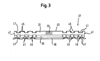
Figur 3- einen Kugelkäfig des Auszugssystems.
- FIG. 1
- an extension system in a cooking appliance;
- FIG. 2
- in a sectional view of the extension system of the cooking appliance; and
- FIG. 3
- a ball cage of the extension system.
In der
Vorliegend ist das Auszugssystem 13 als ein Teleskopauszug ausgebildet. Der Teleskopauszug 13 ist gemäß der
Die Ausgestaltung der Schienen 23, 25, 27 ist nicht auf das vorliegende Ausführungsbeispiel beschränkt. So kann die Halteschiene 23 auch wie ein Rundstab 11 ausgebildet sein. Auf der Halteschiene 23 kann die Auszugsschiene gleitend oder über andere Wälzkörper gelagert geführt sein. Dabei ist die Ausgestaltung der Auszugsschiene 27 nicht auf das vorliegende Ausführungsbeispiel beschränkt. Vielmehr kann die Auszugsschiene 27 auch als ein Schlitten, ein Läufer oder ein sonstiges Auszugselement ausgebildet sein. Zwischen dem Auszugselement 27 und der Halteschiene 23 kann auch auf die Anordnung der Zwischenschiene 25 verzichtet werden.The configuration of the
Die Halteschiene 23 und die Auszugsschiene 27 bestehen gemäß der
Um ein leichtgängiges Herausziehen und Zusammenschieben des Auszugssystems zu gestatten, ist die Zwischenschiene 25 mit einer Schmierstoffschicht 33 beschichtet. Die Schmierstoffschicht 33 ist in der
Alternativ kann die Halteschiene 23 und/oder die Auszugsschiene 27 mit einer zweiten Schicht beschichtet sein, wie sie in der
Vorliegend weist die Schmierstoffschicht 33 Partikel aus einem anorganischen Festschmierstoff, wie etwa Graphit auf. Zur Herstellung der Schmierstoffschicht 33 wird zunächst ein Pulver des anorganischen Festschmierstoffs in einer Lacklösung suspendiert und damit anschließend die Zwischenschiene 25 beschichtet. In einem weiteren Arbeitsschritt wird die Lacklösung in die Zwischenschiene 25 eingebrannt. Dadurch ergibt sich eine äußerst hohe mechanische Abriebsfestigkeit der Beschichtung 33 sowie eine gute chemische Widerstandsfähigkeit gegenüber aggressiven Medien, wie etwa Waschmitteln. Neben diesem kostengünstigen Lackierverfahren sind auch andere Verfahren, wie etwa eine PVD-Beschichtung (Physical Vapour Deposition) oder eine CVD-Beschichtung (Chemical Vapour Deposition) zur Herstellung der Schmierstoffschicht 33 denkbar.In the present case, the
Die Schmierstoffschicht 33 der Zwischenschiene 25 reicht aus, um auch zwischen den Kugeln 29 und der Auszugsschiene 27 bzw. der Halteschiene 23 genügend Schmierstoff einzubringen. Die in der
Erst ein solcher Schutz der Zwischenschiene 25 vor Verunreinigungen ermöglicht daher sinnvoller Weise eine Beschichtung der Zwischenschiene 25 mit der anorganischen Festschmierstoffschicht 33. Eine derartige Schicht ist nämlich - verglichen etwa mit einer auf PTFE basierenden Schicht - nur sehr schwer zu reinigen.Only such a protection of the
Gemäß den
Die in den
Die Kugelkäfige 37 sind zwischen den Schienen 23, 25, 27 in Längsrichtung frei beweglich. Die Stirnseiten 47 jedes Kugelkäfigs 37 dienen in dem in der
Claims (23)
- Pull-out system for a domestic appliance, particularly cooking appliance, which has at least one pull-out element (25) which is protected by a cover element (23, 27) from contaminations, characterised in that the pull-out element (25) has a lubricant layer (33), which comprises a binder which keeps the lubricant at a rail or a roller body cage (37), and that the binder is a lacquer.
- Pull-out system according to claim 1, characterised in that the lubricant layer (33) comprises an inorganic solid lubricant.
- Pull-out system according to claim 1 or 2, characterised in that the lubricant layer (33) comprises graphite.
- Pull-out system according to any one of the preceding claims, characterised in that the lubricant layer (33) comprises molybdenum disulfide.
- Pull-out system according to any one of the preceding claims, characterised in that the lubricant layer (33) comprises boron nitride.
- Pull-out system according to any one of the preceding claims, characterised in that the lubricant layer (33) comprises tungsten disulfide.
- Pull-out system according to any one of the preceding claims, characterised in that the lubricant layer (33) is formed to be chemically resistant.
- Pull-out system according to any one of the preceding claims, characterised in that the lubricant layer (33) is formed to be resistant to high temperature.
- Pull-out system according to any one of the preceding claims, characterised in that the lacquer with the lubricant is baked into the pull-out element (25)
- Pull-out system according to any one of the preceding claims, characterised in that the pull-out element (25) is mounted in the pull-out system by way of roller bearings (29).
- Pull-out system according to claim 10, characterised in that the roller bodies (29) are arranged in a roller body cage (37).
- Pull-out system according to claim 11, characterised in that the roller body cage (37) is constructed as an abutment for limiting movement of the pull-out element (25).
- Pull-out system according to one of claims 11 and 12, characterised in that the roller body cage (37) is coated with the lubricant layer (33).
- Pull-out system according to any one of the preceding claims, characterised in that the pull-out element (25) is completed coated with the lubricant layer (33).
- Pull-out system according to any one of the preceding claims, characterised in that the lubricant layer (33) is formed to be multi-layered at least in part.
- Pull-out system according to any one of the preceding claims, characterised in that the lubricant layer (33) contains further fillers, particularly of ceramic.
- Pull-out system according to any one of the preceding claims, characterised in that the pull-out system (13) is withdrawably mounted in the domestic appliance.
- Pull-out system according to any one of the preceding claims, characterised in that the cover element (23, 27) is a stationary mounting rail (23), at which the pull-out element (25) is mounted, of the pull-out system.
- Pull-out system according to any one of the preceding claims, characterised in that the cover element (23, 27) is a movable pull-out rail (27), which is mounted on the pull-out element (25).
- Pull-out system according to claim 19, characterised in that the pull-out element (25) is constructed as an intermediate rail which is mounted between the stationary mounting rail (23) and the movable pull-out rail (27).
- Pull-out system according to claim 20, characterised in that the mounting rail (23) and/or the pull-out rail (27) encloses or enclose the intermediate rail (25).
- Pull-out system according to claim 21, characterised in that the mounting rail (23) and/or the pull-out rail (27) bound a cavity (31) in which the intermediate rail (25) is arranged.
- Domestic appliance with a pull-out system according to any one of the preceding claims.
Applications Claiming Priority (2)
| Application Number | Priority Date | Filing Date | Title |
|---|---|---|---|
| DE102004019103A DE102004019103A1 (en) | 2004-04-20 | 2004-04-20 | Pull-out system for a household appliance |
| DE102004019103 | 2004-04-20 |
Publications (2)
| Publication Number | Publication Date |
|---|---|
| EP1589290A1 EP1589290A1 (en) | 2005-10-26 |
| EP1589290B1 true EP1589290B1 (en) | 2010-03-10 |
Family
ID=34939386
Family Applications (1)
| Application Number | Title | Priority Date | Filing Date |
|---|---|---|---|
| EP05103136A Revoked EP1589290B1 (en) | 2004-04-20 | 2005-04-19 | Extraction system for a household appliance |
Country Status (4)
| Country | Link |
|---|---|
| EP (1) | EP1589290B1 (en) |
| AT (1) | ATE460628T1 (en) |
| DE (2) | DE102004019103A1 (en) |
| ES (1) | ES2340592T3 (en) |
Families Citing this family (6)
| Publication number | Priority date | Publication date | Assignee | Title |
|---|---|---|---|---|
| DE102005037016A1 (en) * | 2005-08-05 | 2007-02-08 | BSH Bosch und Siemens Hausgeräte GmbH | Hausgeräte extracting device |
| DE102006030228A1 (en) | 2006-06-30 | 2008-01-03 | BSH Bosch und Siemens Hausgeräte GmbH | Household appliance and pull-out system for a household appliance |
| DE202008012997U1 (en) * | 2008-09-30 | 2010-02-18 | Paul Hettich Gmbh & Co. Kg | Rail of a furniture drawer guide |
| DE202008012998U1 (en) * | 2008-09-30 | 2010-02-25 | Paul Hettich Gmbh & Co. Kg | Pull-out guide for a furniture pull-out part such as a drawer |
| DE102011120736B4 (en) * | 2011-02-01 | 2021-08-12 | Laag S.R.L. | Pull-out guide for an oven or for a dishwasher |
| DE102017203135A1 (en) * | 2017-02-27 | 2018-08-30 | BSH Hausgeräte GmbH | Rail extension device with at least noise reducing additional part on a rail and home appliance with a rail extension device |
Family Cites Families (10)
| Publication number | Priority date | Publication date | Assignee | Title |
|---|---|---|---|---|
| DE3815440A1 (en) * | 1988-05-06 | 1989-11-16 | Licentia Gmbh | Telescopic slide-in device for supporting supports for material to be cooked, especially for baking ovens |
| DE3922843A1 (en) * | 1989-07-11 | 1991-01-24 | Bosch Siemens Hausgeraete | ARRANGEMENT OF AN OVEN FITTED WITH TELESCOPE |
| DE19847727C2 (en) | 1998-10-16 | 2000-09-28 | Aeg Hausgeraete Gmbh | Telescopic pull-out device for food carriers in the cooking space of household ovens |
| DE19859986A1 (en) * | 1998-12-23 | 2000-06-29 | Bsh Bosch Siemens Hausgeraete | Telescopic pull-out device for household appliances and furniture |
| DE19949239A1 (en) * | 1999-10-13 | 2001-04-26 | Aeg Hausgeraete Gmbh | Extraction device for at least one cooking item bearer in cooker oven has bearings for rails with bearing balls or rollers consisting of self-lubricating material, at least one their surfaces |
| US6569816B2 (en) * | 2000-08-18 | 2003-05-27 | Ntn Corporation | Composition having lubricity and product comprising the composition |
| DE10054954B4 (en) | 2000-11-06 | 2004-10-21 | AEG Hausgeräte GmbH | Cooking oven with pull-out device for food carriers |
| DE10211470A1 (en) * | 2002-03-15 | 2003-10-02 | Electrolux Home Prod Corp | Rail of a telescopic pull-out system, in particular, for items to be cooked in a cooking oven and pull-out system |
| TWI224184B (en) * | 2002-07-10 | 2004-11-21 | Accuride Int Inc | Extendable oven rack assembly |
| DE10330348B4 (en) | 2003-07-05 | 2007-01-25 | Accuride International Gmbh | Gargutträgerauszugsystem |
-
2004
- 2004-04-20 DE DE102004019103A patent/DE102004019103A1/en not_active Withdrawn
-
2005
- 2005-04-19 ES ES05103136T patent/ES2340592T3/en active Active
- 2005-04-19 EP EP05103136A patent/EP1589290B1/en not_active Revoked
- 2005-04-19 DE DE502005009167T patent/DE502005009167D1/en active Active
- 2005-04-19 AT AT05103136T patent/ATE460628T1/en not_active IP Right Cessation
Also Published As
| Publication number | Publication date |
|---|---|
| DE102004019103A1 (en) | 2005-11-17 |
| DE502005009167D1 (en) | 2010-04-22 |
| EP1589290A1 (en) | 2005-10-26 |
| ES2340592T3 (en) | 2010-06-07 |
| ATE460628T1 (en) | 2010-03-15 |
Similar Documents
| Publication | Publication Date | Title |
|---|---|---|
| EP1589289B1 (en) | Pull-out system for household appliance | |
| EP1589291B1 (en) | Pull-out system for household appliance | |
| EP1873460B1 (en) | Domestic appliance and pullout system for a domestic appliance | |
| CH695114A5 (en) | Shelf for food support in the cooking of Garöfen. | |
| DE102011120736B4 (en) | Pull-out guide for an oven or for a dishwasher | |
| DE102008053504B4 (en) | Pull-out guide for furniture | |
| EP1589290B1 (en) | Extraction system for a household appliance | |
| EP0994309B1 (en) | Withdrawal device for food support in a baking oven | |
| DE102012104129B4 (en) | Excerpt guide | |
| EP1014004B2 (en) | Telescopic withdrawal device for household appliances and furniture | |
| WO2018189098A1 (en) | Telescopic rail | |
| EP3172492A1 (en) | Roller, deployment system, and domestic cooking appliance | |
| EP2342503B1 (en) | Pull-out guide and baking oven | |
| DE202014009194U1 (en) | Pull-out system and household cooker | |
| DE102010041516A1 (en) | Extraction device for at least one food support of a household appliance and domestic appliance with such a pull-out device | |
| DE102009003741A1 (en) | Pull-out guide and oven and process for their coating | |
| DE202014001024U1 (en) | Device for guiding a drawer and furniture with such a device | |
| DE102005037016A1 (en) | Hausgeräte extracting device | |
| DE102016218748A1 (en) | Rail extension device with two rails and in each case at least one rolling element arranged thereon as well as household refrigeration device with a rail extension device | |
| DE102015202631B4 (en) | Bearings and procedures | |
| DE102012218006A1 (en) | Domestic appliance e.g. oven, has bearing with surface structure which is adapted to to-be-stored lubricant | |
| DE102014225890A1 (en) | Pull-out system and household cooker | |
| WO2018153715A1 (en) | Rail expansion joint having an additional part which at least reduces running noise on a ball cage, and domestic appliance having a rail expansion joint |
Legal Events
| Date | Code | Title | Description |
|---|---|---|---|
| PUAI | Public reference made under article 153(3) epc to a published international application that has entered the european phase |
Free format text: ORIGINAL CODE: 0009012 |
|
| AK | Designated contracting states |
Kind code of ref document: A1 Designated state(s): AT BE BG CH CY CZ DE DK EE ES FI FR GB GR HU IE IS IT LI LT LU MC NL PL PT RO SE SI SK TR |
|
| AX | Request for extension of the european patent |
Extension state: AL BA HR LV MK YU |
|
| 17P | Request for examination filed |
Effective date: 20060426 |
|
| AKX | Designation fees paid |
Designated state(s): AT BE BG CH CY CZ DE DK EE ES FI FR GB GR HU IE IS IT LI LT LU MC NL PL PT RO SE SI SK TR |
|
| 17Q | First examination report despatched |
Effective date: 20080520 |
|
| GRAP | Despatch of communication of intention to grant a patent |
Free format text: ORIGINAL CODE: EPIDOSNIGR1 |
|
| GRAS | Grant fee paid |
Free format text: ORIGINAL CODE: EPIDOSNIGR3 |
|
| GRAA | (expected) grant |
Free format text: ORIGINAL CODE: 0009210 |
|
| AK | Designated contracting states |
Kind code of ref document: B1 Designated state(s): AT BE BG CH CY CZ DE DK EE ES FI FR GB GR HU IE IS IT LI LT LU MC NL PL PT RO SE SI SK TR |
|
| REG | Reference to a national code |
Ref country code: GB Ref legal event code: FG4D Free format text: NOT ENGLISH |
|
| REG | Reference to a national code |
Ref country code: CH Ref legal event code: EP |
|
| REG | Reference to a national code |
Ref country code: IE Ref legal event code: FG4D |
|
| REF | Corresponds to: |
Ref document number: 502005009167 Country of ref document: DE Date of ref document: 20100422 Kind code of ref document: P |
|
| REG | Reference to a national code |
Ref country code: ES Ref legal event code: FG2A Ref document number: 2340592 Country of ref document: ES Kind code of ref document: T3 |
|
| REG | Reference to a national code |
Ref country code: NL Ref legal event code: VDEP Effective date: 20100310 |
|
| PG25 | Lapsed in a contracting state [announced via postgrant information from national office to epo] |
Ref country code: LT Free format text: LAPSE BECAUSE OF FAILURE TO SUBMIT A TRANSLATION OF THE DESCRIPTION OR TO PAY THE FEE WITHIN THE PRESCRIBED TIME-LIMIT Effective date: 20100310 |
|
| LTIE | Lt: invalidation of european patent or patent extension |
Effective date: 20100310 |
|
| PG25 | Lapsed in a contracting state [announced via postgrant information from national office to epo] |
Ref country code: FI Free format text: LAPSE BECAUSE OF FAILURE TO SUBMIT A TRANSLATION OF THE DESCRIPTION OR TO PAY THE FEE WITHIN THE PRESCRIBED TIME-LIMIT Effective date: 20100310 Ref country code: PL Free format text: LAPSE BECAUSE OF FAILURE TO SUBMIT A TRANSLATION OF THE DESCRIPTION OR TO PAY THE FEE WITHIN THE PRESCRIBED TIME-LIMIT Effective date: 20100310 Ref country code: SI Free format text: LAPSE BECAUSE OF FAILURE TO SUBMIT A TRANSLATION OF THE DESCRIPTION OR TO PAY THE FEE WITHIN THE PRESCRIBED TIME-LIMIT Effective date: 20100310 |
|
| REG | Reference to a national code |
Ref country code: IE Ref legal event code: FD4D |
|
| PG25 | Lapsed in a contracting state [announced via postgrant information from national office to epo] |
Ref country code: SE Free format text: LAPSE BECAUSE OF FAILURE TO SUBMIT A TRANSLATION OF THE DESCRIPTION OR TO PAY THE FEE WITHIN THE PRESCRIBED TIME-LIMIT Effective date: 20100310 Ref country code: RO Free format text: LAPSE BECAUSE OF FAILURE TO SUBMIT A TRANSLATION OF THE DESCRIPTION OR TO PAY THE FEE WITHIN THE PRESCRIBED TIME-LIMIT Effective date: 20100310 Ref country code: CY Free format text: LAPSE BECAUSE OF FAILURE TO SUBMIT A TRANSLATION OF THE DESCRIPTION OR TO PAY THE FEE WITHIN THE PRESCRIBED TIME-LIMIT Effective date: 20100310 Ref country code: EE Free format text: LAPSE BECAUSE OF FAILURE TO SUBMIT A TRANSLATION OF THE DESCRIPTION OR TO PAY THE FEE WITHIN THE PRESCRIBED TIME-LIMIT Effective date: 20100310 Ref country code: GR Free format text: LAPSE BECAUSE OF FAILURE TO SUBMIT A TRANSLATION OF THE DESCRIPTION OR TO PAY THE FEE WITHIN THE PRESCRIBED TIME-LIMIT Effective date: 20100611 Ref country code: NL Free format text: LAPSE BECAUSE OF FAILURE TO SUBMIT A TRANSLATION OF THE DESCRIPTION OR TO PAY THE FEE WITHIN THE PRESCRIBED TIME-LIMIT Effective date: 20100310 |
|
| BERE | Be: lapsed |
Owner name: BSH BOSCH UND SIEMENS HAUSGERATE G.M.B.H. Effective date: 20100430 |
|
| PG25 | Lapsed in a contracting state [announced via postgrant information from national office to epo] |
Ref country code: BG Free format text: LAPSE BECAUSE OF FAILURE TO SUBMIT A TRANSLATION OF THE DESCRIPTION OR TO PAY THE FEE WITHIN THE PRESCRIBED TIME-LIMIT Effective date: 20100610 Ref country code: IS Free format text: LAPSE BECAUSE OF FAILURE TO SUBMIT A TRANSLATION OF THE DESCRIPTION OR TO PAY THE FEE WITHIN THE PRESCRIBED TIME-LIMIT Effective date: 20100710 Ref country code: MC Free format text: LAPSE BECAUSE OF NON-PAYMENT OF DUE FEES Effective date: 20100430 Ref country code: SK Free format text: LAPSE BECAUSE OF FAILURE TO SUBMIT A TRANSLATION OF THE DESCRIPTION OR TO PAY THE FEE WITHIN THE PRESCRIBED TIME-LIMIT Effective date: 20100310 Ref country code: CZ Free format text: LAPSE BECAUSE OF FAILURE TO SUBMIT A TRANSLATION OF THE DESCRIPTION OR TO PAY THE FEE WITHIN THE PRESCRIBED TIME-LIMIT Effective date: 20100310 |
|
| REG | Reference to a national code |
Ref country code: CH Ref legal event code: PL |
|
| PLBI | Opposition filed |
Free format text: ORIGINAL CODE: 0009260 |
|
| PLAX | Notice of opposition and request to file observation + time limit sent |
Free format text: ORIGINAL CODE: EPIDOSNOBS2 |
|
| 26 | Opposition filed |
Opponent name: PAUL HETTICH GMBH & CO. KG Effective date: 20101208 |
|
| PG25 | Lapsed in a contracting state [announced via postgrant information from national office to epo] |
Ref country code: PT Free format text: LAPSE BECAUSE OF FAILURE TO SUBMIT A TRANSLATION OF THE DESCRIPTION OR TO PAY THE FEE WITHIN THE PRESCRIBED TIME-LIMIT Effective date: 20100712 Ref country code: DK Free format text: LAPSE BECAUSE OF FAILURE TO SUBMIT A TRANSLATION OF THE DESCRIPTION OR TO PAY THE FEE WITHIN THE PRESCRIBED TIME-LIMIT Effective date: 20100310 Ref country code: IE Free format text: LAPSE BECAUSE OF FAILURE TO SUBMIT A TRANSLATION OF THE DESCRIPTION OR TO PAY THE FEE WITHIN THE PRESCRIBED TIME-LIMIT Effective date: 20100310 |
|
| PG25 | Lapsed in a contracting state [announced via postgrant information from national office to epo] |
Ref country code: LI Free format text: LAPSE BECAUSE OF NON-PAYMENT OF DUE FEES Effective date: 20100430 Ref country code: CH Free format text: LAPSE BECAUSE OF NON-PAYMENT OF DUE FEES Effective date: 20100430 |
|
| PG25 | Lapsed in a contracting state [announced via postgrant information from national office to epo] |
Ref country code: BE Free format text: LAPSE BECAUSE OF NON-PAYMENT OF DUE FEES Effective date: 20100430 |
|
| PLAF | Information modified related to communication of a notice of opposition and request to file observations + time limit |
Free format text: ORIGINAL CODE: EPIDOSCOBS2 |
|
| PLAF | Information modified related to communication of a notice of opposition and request to file observations + time limit |
Free format text: ORIGINAL CODE: EPIDOSCOBS2 |
|
| PG25 | Lapsed in a contracting state [announced via postgrant information from national office to epo] |
Ref country code: AT Free format text: LAPSE BECAUSE OF NON-PAYMENT OF DUE FEES Effective date: 20100419 |
|
| PLBB | Reply of patent proprietor to notice(s) of opposition received |
Free format text: ORIGINAL CODE: EPIDOSNOBS3 |
|
| PG25 | Lapsed in a contracting state [announced via postgrant information from national office to epo] |
Ref country code: LU Free format text: LAPSE BECAUSE OF NON-PAYMENT OF DUE FEES Effective date: 20100419 Ref country code: HU Free format text: LAPSE BECAUSE OF FAILURE TO SUBMIT A TRANSLATION OF THE DESCRIPTION OR TO PAY THE FEE WITHIN THE PRESCRIBED TIME-LIMIT Effective date: 20100911 |
|
| PGFP | Annual fee paid to national office [announced via postgrant information from national office to epo] |
Ref country code: ES Payment date: 20120423 Year of fee payment: 8 |
|
| REG | Reference to a national code |
Ref country code: DE Ref legal event code: R064 Ref document number: 502005009167 Country of ref document: DE Ref country code: DE Ref legal event code: R103 Ref document number: 502005009167 Country of ref document: DE |
|
| RDAF | Communication despatched that patent is revoked |
Free format text: ORIGINAL CODE: EPIDOSNREV1 |
|
| RDAG | Patent revoked |
Free format text: ORIGINAL CODE: 0009271 |
|
| STAA | Information on the status of an ep patent application or granted ep patent |
Free format text: STATUS: PATENT REVOKED |
|
| PGFP | Annual fee paid to national office [announced via postgrant information from national office to epo] |
Ref country code: DE Payment date: 20130430 Year of fee payment: 9 Ref country code: GB Payment date: 20130422 Year of fee payment: 9 |
|
| 27W | Patent revoked |
Effective date: 20130227 |
|
| GBPR | Gb: patent revoked under art. 102 of the ep convention designating the uk as contracting state |
Effective date: 20130227 |
|
| PGFP | Annual fee paid to national office [announced via postgrant information from national office to epo] |
Ref country code: IT Payment date: 20130424 Year of fee payment: 9 Ref country code: FR Payment date: 20130523 Year of fee payment: 9 Ref country code: TR Payment date: 20130410 Year of fee payment: 9 |
|
| REG | Reference to a national code |
Ref country code: DE Ref legal event code: R107 Ref document number: 502005009167 Country of ref document: DE Effective date: 20131107 |
|
| REG | Reference to a national code |
Ref country code: AT Ref legal event code: MA03 Ref document number: 460628 Country of ref document: AT Kind code of ref document: T Effective date: 20100227 |
|
| PG25 | Lapsed in a contracting state [announced via postgrant information from national office to epo] |
Ref country code: AT Free format text: THE PATENT HAS BEEN ANNULLED BY A DECISION OF A NATIONAL AUTHORITY Effective date: 20100227 |