EP1589267A1 - Vanne de régulation de débit avec dispositif d'indication de l'état du fluide - Google Patents
Vanne de régulation de débit avec dispositif d'indication de l'état du fluide Download PDFInfo
- Publication number
- EP1589267A1 EP1589267A1 EP20040014459 EP04014459A EP1589267A1 EP 1589267 A1 EP1589267 A1 EP 1589267A1 EP 20040014459 EP20040014459 EP 20040014459 EP 04014459 A EP04014459 A EP 04014459A EP 1589267 A1 EP1589267 A1 EP 1589267A1
- Authority
- EP
- European Patent Office
- Prior art keywords
- plunger
- valve according
- status
- ducts
- head
- Prior art date
- Legal status (The legal status is an assumption and is not a legal conclusion. Google has not performed a legal analysis and makes no representation as to the accuracy of the status listed.)
- Granted
Links
Images


Classifications
-
- G—PHYSICS
- G01—MEASURING; TESTING
- G01L—MEASURING FORCE, STRESS, TORQUE, WORK, MECHANICAL POWER, MECHANICAL EFFICIENCY, OR FLUID PRESSURE
- G01L19/00—Details of, or accessories for, apparatus for measuring steady or quasi-steady pressure of a fluent medium insofar as such details or accessories are not special to particular types of pressure gauges
- G01L19/08—Means for indicating or recording, e.g. for remote indication
- G01L19/10—Means for indicating or recording, e.g. for remote indication mechanical
-
- G—PHYSICS
- G05—CONTROLLING; REGULATING
- G05D—SYSTEMS FOR CONTROLLING OR REGULATING NON-ELECTRIC VARIABLES
- G05D7/00—Control of flow
- G05D7/01—Control of flow without auxiliary power
- G05D7/0126—Control of flow without auxiliary power the sensing element being a piston or plunger associated with one or more springs
-
- Y—GENERAL TAGGING OF NEW TECHNOLOGICAL DEVELOPMENTS; GENERAL TAGGING OF CROSS-SECTIONAL TECHNOLOGIES SPANNING OVER SEVERAL SECTIONS OF THE IPC; TECHNICAL SUBJECTS COVERED BY FORMER USPC CROSS-REFERENCE ART COLLECTIONS [XRACs] AND DIGESTS
- Y10—TECHNICAL SUBJECTS COVERED BY FORMER USPC
- Y10T—TECHNICAL SUBJECTS COVERED BY FORMER US CLASSIFICATION
- Y10T137/00—Fluid handling
- Y10T137/8158—With indicator, register, recorder, alarm or inspection means
- Y10T137/8326—Fluid pressure responsive indicator, recorder or alarm
Definitions
- the present invention relates to a flow control valve with device for indicating the status of a fluid, particularly for gas containers.
- Those conventional devices allow to separate, when required, the user devices from the cylinder in which the fluid is contained.
- a pressure sensing means is also known for checking the tightness of the system components that connect the cylinder to the user devices; this means still provides for the application of devices that are external with respect to the valve.
- US-6182692 discloses a valve unit that includes a pressure gauge integrated in the handwheel
- EP-A-0869310 discloses a tap for gas cylinders that includes a pressure gauge integrated in the knob.
- the aim of the present invention is to provide a valve equipped with a device for indicating the status of a fluid that is improved with respect to the devices of the background art.
- an object of the invention is to provide a valve equipped with a device for indicating the status of a fluid that withstands pressures even several times higher than the measurement interval for which the device is designed.
- a further object of the invention is to provide a valve equipped with a device that can be adapted to different gases.
- a further object is to provide a valve in which the status indication device is capable of giving an indication of the quantity of fluid contained in the cylinder without requiring the presence of external components, ensuring higher safety and practicality in use.
- a further object is to provide a valve equipped with a device that allows to monitor the status of the system that connects the cylinder on which it is installed to the user devices, again without requiring the presence of additional components in the system.
- a further object is to allow the replacement, if necessary, of the pressure sensing means without requiring complete removal of the flow control valve from the cylinder.
- a further object of the invention is to provide a valve that can be obtained by assembling components that are easily available and low in cost, so as to ensure an advantage on a purely economic level.
- a flow control valve with device for indicating the status of a fluid, particularly for gas containers comprising a body provided with an end on which a threaded shank is provided for hermetic coupling to a gas container, and a handwheel, characterized in that a gas status indicator device is included within the handwheel, the device comprising a plunger that is constituted by a head and by a helical stem that is engaged in a cavity of a body that can rotate so that an axial movement of the plunger is matched by a rotation of the rotatable body, which has a visible portion that is marked so as to provide an indication of the status of the plunger, which can move, in contrast with a calibrated spring, between at least one minimum position, in which the head abuts against a shoulder, due to the action of the calibrated spring, and a maximum position, in which the plunger abuts against an end of the rotatable body.
- a valve according to the invention generally designated by the reference numeral 100, includes a body 2, which has an end 21 on which a threaded shank 4 is provided for hermetic coupling to a cylinder, not shown in the figures.
- the body 2 includes a region 5, which provides an hermetic connection to the system for supplying the user devices, which is not visible in the figures.
- a first feed duct 9 is formed inside the shank 4, and a second feed duct 10 is formed inside the region for connection to the user devices; the ducts allow the passage of the fluid that arrives from the cylinder and is directed to the user devices.
- the ducts 9 and 10 are connected by means of a passage 12, which is formed in the region where they intersect.
- the body 2 has a region 22 inside which a piston 3 is accommodated; the piston forms a movable closure member, which is capable of passing from an open position, in which the ducts 9 and 10 are mutually connected by the passage 12, as shown in Figure 4, and a flow control or closure position, in which the passage is no longer present, interrupting the connection between the ducts 9 and 10, and vice versa.
- the movable member 3 includes a handwheel 15 and can slide within the body 2 by means of a threaded coupling 11.
- the movable member 3 includes a flow control portion 32, which closes the duct 9 hermetically by means of the gasket 6, blocking the passage 12 and preventing the flow of the fluid contained in the cylinder toward the duct 10.
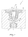
- the handwheel 15 includes the device 1 internally and has for this purpose, in the illustrated example, a cavity 24 suitable to accommodate the device 1.
- the device 1 includes a plunger 40, which is constituted by a head 41 and by a helical stem 42, which engages a cavity 43 of a rotating body 44 so that a translational motion of the plunger 40, which cannot rotate about the longitudinal axis 45, is matched by a rotation of the rotatable body 44.
- the movement of the plunger 40 is contrasted by a spring 46, which is mounted coaxially with respect to the stem 42, so as to push the head 41 of the plunger 40 in abutment against a shoulder 47, which is formed along an axial chamber 48, which in turn is formed in the movable member 3.
- the axial chamber 48 is connected to the ducts 9 and 10 by a radial channel 49.
- the rotatable body 44 can rotate within the cavity 24, which is closed upward by a transparent dome 50.
- the pressure that is present inside the ducts 9 and 10 determines the axial position of the plunger 40, which has two end positions, one for pressure below a certain limit, shown in Figure 3, in which the spring 46 pushes the head 41 into abutment against the shoulder 47, and one for maximum pressure, shown in Figure 2, in which the head 41 abuts against the end 51 of the rotatable body 44.
- the device 1 is therefore capable of measuring the pressure inside the ducts 9 and 10 in an interval that depends on the calibration of the spring 46.
- Two annular gaskets 52 are provided above the channel 49, between the movable member 3 and the body 2, in order to isolate the upper part of the movable member 3.
- the device according to the invention is capable of giving an indication of the amount of gas that is present in a cylinder by showing the variation on a "dial", which in the specific case is constituted by the upper surface of the rotatable body 44, of some sort of indicator, colors, numbers, or geometric shapes.
- the device according to the invention can be adapted to different gases.
- An important characteristic of the present invention is that it can be subjected without damage to hydraulic tightness tests usually performed at a much higher pressure, ten to fifty times higher, than the operating range for which the spring 46 is calibrated.
- the device according to the invention can be arranged upstream or downstream of the main seal, and in this case monitoring changes from continuous to operation only when the valve is open.
- the valve When the device is arranged downstream of the main seal, if the valve is closed, it detects the presence of leaks in the user device line part.
- the device can be positioned in any point of a valve, of a line or of a flow control and pressure reduction device.
- Figure 5 in fact illustrates a different application, among the many possible ones, of the device according to the invention.
- Another advantage of the device according to the invention is the possibility to manage its dimensions independently of the indicated delta P values.
- Another possibility offered by the device is to vary the sensitivity of the indication within a delta P by varying the winding pitch of the helix of the stem 42.
- the device can be arranged inside the movable member, which constitutes the handwheel, also by way of the presence of the tangent locking pin 8, which allows a considerable reduction in space occupation and complete accessibility to the interior.
- the invention achieves the intended aim and objects by providing a valve that is improved with respect to hitherto known devices and with advantages also from the production standpoint, since it is produced with a reduced number of components, with consequent economic advantages with respect to known indication methods.
- the materials used, as well as the dimensions, may of course be any according to requirements and to the state of the art.
Landscapes
- Physics & Mathematics (AREA)
- General Physics & Mathematics (AREA)
- Engineering & Computer Science (AREA)
- Automation & Control Theory (AREA)
- Indication Of The Valve Opening Or Closing Status (AREA)
- Filling Or Discharging Of Gas Storage Vessels (AREA)
Applications Claiming Priority (2)
| Application Number | Priority Date | Filing Date | Title |
|---|---|---|---|
| ITMI20040770 | 2004-04-20 | ||
| ITMI20040770 ITMI20040770A1 (it) | 2004-04-20 | 2004-04-20 | Valvola intercettatrice con dispositivo indicatore di stato di un fluido particolarmente per contenitori di gas |
Publications (2)
| Publication Number | Publication Date |
|---|---|
| EP1589267A1 true EP1589267A1 (fr) | 2005-10-26 |
| EP1589267B1 EP1589267B1 (fr) | 2007-01-03 |
Family
ID=34925422
Family Applications (1)
| Application Number | Title | Priority Date | Filing Date |
|---|---|---|---|
| EP20040014459 Expired - Lifetime EP1589267B1 (fr) | 2004-04-20 | 2004-06-21 | Vanne de régulation de débit avec dispositif d'indication de l'état du fluide |
Country Status (9)
| Country | Link |
|---|---|
| US (1) | US7134449B2 (fr) |
| EP (1) | EP1589267B1 (fr) |
| CN (1) | CN100389280C (fr) |
| AT (1) | ATE350610T1 (fr) |
| AU (1) | AU2004203334B2 (fr) |
| CA (1) | CA2475945C (fr) |
| DE (1) | DE602004004081D1 (fr) |
| IT (1) | ITMI20040770A1 (fr) |
| MX (1) | MXPA04008301A (fr) |
Cited By (1)
| Publication number | Priority date | Publication date | Assignee | Title |
|---|---|---|---|---|
| US20130233417A1 (en) * | 2010-06-07 | 2013-09-12 | Bermad Cs Ltd. | Hydraulic torrent control valve |
Families Citing this family (18)
| Publication number | Priority date | Publication date | Assignee | Title |
|---|---|---|---|---|
| US9104208B2 (en) * | 2011-08-19 | 2015-08-11 | Emerson Process Management Regulator Technologies, Inc. | Regulator with bleed valve |
| US20130299017A1 (en) * | 2012-01-13 | 2013-11-14 | Fluid Handling Llc | Flow rate scale field calibration for balancing valve |
| LU91948B1 (fr) | 2012-03-01 | 2013-09-02 | Luxembourg Patent Co | Robinet pour bouteille de gaz avec indicateur visuel de pression |
| CA2869909C (fr) | 2012-04-09 | 2020-03-31 | Flow Control Llc. | Pompe a membrane pneumatique |
| FR2991432B1 (fr) * | 2012-06-04 | 2015-02-06 | Air Liquide | Bouchon pour raccord fluidique, robinet, bouteille et procede de remplissage correspondants |
| JP6179510B2 (ja) * | 2012-06-14 | 2017-08-16 | Smc株式会社 | 流量制御装置 |
| WO2014152197A2 (fr) * | 2013-03-15 | 2014-09-25 | Scott Technologies, Inc. | Systèmes de remplissage d'une bouteille de gaz |
| ITPD20130203A1 (it) * | 2013-07-19 | 2015-01-20 | Bassi Offshore S R L | Leak detector |
| US9417148B2 (en) | 2013-07-26 | 2016-08-16 | Western/Scott Fetzer Company | Indicating assembly for a pressurized container |
| ES2728454T3 (es) * | 2013-08-06 | 2019-10-24 | Air Prod & Chem | Aparato de control para un regulador de presión de gas |
| CN104236784B (zh) * | 2014-07-18 | 2016-07-06 | 格力休闲体育用品有限公司 | 一种压力表 |
| FR3042586B1 (fr) | 2015-10-15 | 2018-03-09 | L'air Liquide, Societe Anonyme Pour L'etude Et L'exploitation Des Procedes Georges Claude | Bouteille de fluide sous pression |
| FR3054638B1 (fr) * | 2016-07-26 | 2019-05-10 | L'air Liquide, Societe Anonyme Pour L'etude Et L'exploitation Des Procedes Georges Claude | Robinet et dispositif de fourniture de fluide sous pression |
| CN106523778A (zh) * | 2016-12-03 | 2017-03-22 | 吴小艇 | 防烫伤的冷热水混合控制开关 |
| FR3095685B1 (fr) * | 2019-05-03 | 2021-04-16 | Air Liquide | Récipient de fluide sous pression avec dispositif indicateur de pression |
| FR3098273B1 (fr) * | 2019-07-05 | 2021-07-02 | Air Liquide | Bouteille de fluide sous pression |
| CN114110174B (zh) * | 2021-10-19 | 2024-10-11 | 宁波华平智控科技股份有限公司 | 一种节流电磁阀 |
| CN117490906B (zh) * | 2023-10-31 | 2025-01-10 | 腾云医疗(深圳)有限公司 | 蒸汽消融设备的测试装置 |
Citations (5)
| Publication number | Priority date | Publication date | Assignee | Title |
|---|---|---|---|---|
| GB888182A (en) * | 1958-03-31 | 1962-01-31 | Dewrance & Co | Improvements in pressure gauges |
| US3975959A (en) * | 1975-02-28 | 1976-08-24 | Sam Larkin | Pressure gauge |
| US5722638A (en) * | 1995-10-20 | 1998-03-03 | Vemco Corporation | Valve with means to block relative rotation of parts during assembly |
| EP0869310A1 (fr) * | 1997-04-01 | 1998-10-07 | GCE Charledave | Robinet à manomètre pour bouteille de gaz comprimé |
| US6182692B1 (en) * | 1999-03-23 | 2001-02-06 | Vti Ventil Technik Gmbh | Valve assembly for an apparatus under pressure |
Family Cites Families (9)
| Publication number | Priority date | Publication date | Assignee | Title |
|---|---|---|---|---|
| US2225690A (en) * | 1937-04-26 | 1940-12-24 | Romort Mfg Company | Charging apparatus for elastic fluids |
| US3250292A (en) * | 1964-03-18 | 1966-05-10 | Ametek Inc | Gauge |
| US3631878A (en) * | 1969-06-23 | 1972-01-04 | Wilkerson Corp | Pilot-operated fluid pressure regulator |
| US3765448A (en) * | 1971-04-06 | 1973-10-16 | Chatham Precision Inc | Flow control valve |
| US4137942A (en) * | 1976-07-15 | 1979-02-06 | W-K-M Wellhead Systems, Inc. | Control valve having integral visual indicator for fluid safety systems |
| US4790821A (en) * | 1987-08-24 | 1988-12-13 | Vance Products Incorporated | Pressure gauge and system |
| GB9719604D0 (en) * | 1997-09-15 | 1997-11-19 | Protector Technologies Bv | Gas regulator/valve device |
| IT1319148B1 (it) * | 2000-11-29 | 2003-09-23 | Cavagna Group Internat Bv Amst | Valvola particolarmente per gas ad azionamento manuale,con mezzi difine corsa in apertura del volantino di azionamento |
| CN2467853Y (zh) * | 2001-02-06 | 2001-12-26 | 上海太设环保设备有限公司 | 车用石油液化气钢瓶组合阀限量输入装置 |
-
2004
- 2004-04-20 IT ITMI20040770 patent/ITMI20040770A1/it unknown
- 2004-06-21 AT AT04014459T patent/ATE350610T1/de not_active IP Right Cessation
- 2004-06-21 EP EP20040014459 patent/EP1589267B1/fr not_active Expired - Lifetime
- 2004-06-21 DE DE200460004081 patent/DE602004004081D1/de not_active Expired - Lifetime
- 2004-07-16 US US10/892,864 patent/US7134449B2/en not_active Expired - Lifetime
- 2004-07-22 AU AU2004203334A patent/AU2004203334B2/en not_active Ceased
- 2004-07-27 CA CA 2475945 patent/CA2475945C/fr not_active Expired - Fee Related
- 2004-08-26 MX MXPA04008301A patent/MXPA04008301A/es not_active Application Discontinuation
- 2004-08-31 CN CNB2004100683635A patent/CN100389280C/zh not_active Expired - Fee Related
Patent Citations (5)
| Publication number | Priority date | Publication date | Assignee | Title |
|---|---|---|---|---|
| GB888182A (en) * | 1958-03-31 | 1962-01-31 | Dewrance & Co | Improvements in pressure gauges |
| US3975959A (en) * | 1975-02-28 | 1976-08-24 | Sam Larkin | Pressure gauge |
| US5722638A (en) * | 1995-10-20 | 1998-03-03 | Vemco Corporation | Valve with means to block relative rotation of parts during assembly |
| EP0869310A1 (fr) * | 1997-04-01 | 1998-10-07 | GCE Charledave | Robinet à manomètre pour bouteille de gaz comprimé |
| US6182692B1 (en) * | 1999-03-23 | 2001-02-06 | Vti Ventil Technik Gmbh | Valve assembly for an apparatus under pressure |
Cited By (3)
| Publication number | Priority date | Publication date | Assignee | Title |
|---|---|---|---|---|
| US20130233417A1 (en) * | 2010-06-07 | 2013-09-12 | Bermad Cs Ltd. | Hydraulic torrent control valve |
| US9400063B2 (en) * | 2010-06-07 | 2016-07-26 | Bermad Cs Ltd. | Hydraulic torrent control valve |
| EP2577129A4 (fr) * | 2010-06-07 | 2016-11-30 | Bermad Cs Ltd | Soupape de commande de torrent hydraulique |
Also Published As
| Publication number | Publication date |
|---|---|
| DE602004004081D1 (de) | 2007-02-15 |
| US20050229981A1 (en) | 2005-10-20 |
| CN100389280C (zh) | 2008-05-21 |
| AU2004203334B2 (en) | 2009-09-24 |
| CA2475945C (fr) | 2008-06-17 |
| AU2004203334A1 (en) | 2005-11-03 |
| CA2475945A1 (fr) | 2005-10-20 |
| MXPA04008301A (es) | 2008-02-19 |
| ITMI20040770A1 (it) | 2004-07-20 |
| CN1690487A (zh) | 2005-11-02 |
| EP1589267B1 (fr) | 2007-01-03 |
| US7134449B2 (en) | 2006-11-14 |
| ATE350610T1 (de) | 2007-01-15 |
Similar Documents
| Publication | Publication Date | Title |
|---|---|---|
| EP1589267B1 (fr) | Vanne de régulation de débit avec dispositif d'indication de l'état du fluide | |
| US5135023A (en) | Pressure regulator | |
| CN103728092B (zh) | 用于高压存储设备的压力表 | |
| US6293297B1 (en) | Air valve housing with pressure indicator | |
| WO2007100579A2 (fr) | Protection d'un capteur de pression contre les surpressions | |
| EP1992931B1 (fr) | Dispositif d'indication de pression | |
| US6161835A (en) | Integrated barrier fluid sealing apparatus with visual volume indicator | |
| EP1522774B1 (fr) | Soupape de régulation de débit | |
| US6318407B1 (en) | Pressure regulator with gauge | |
| US4116157A (en) | Rotatable visual indicator for safety systems | |
| US4246797A (en) | Pressure Indicator | |
| JP5429965B2 (ja) | 圧力調整器 | |
| LU505967B1 (en) | Device for controlling flow or pressure of gas in a cylinder with optimised refill port and pressure indicator | |
| US6694819B1 (en) | Pressure gauge with automatically operated pressure relief valve | |
| US4864871A (en) | Transducer for fluid flow | |
| US4199992A (en) | Pressure indicator | |
| CN105393045A (zh) | 加压流体容器 | |
| KR102308565B1 (ko) | 버튼형 보호스위치가 구비된 압력게이지 | |
| US1242713A (en) | Combined pressure reducing and relief valve. | |
| JP2003329530A (ja) | 漏れ防止部材 | |
| WO2012105356A1 (fr) | Régulateur de pression | |
| US2920646A (en) | Gage protector | |
| WO2000065321A1 (fr) | Jauge de pression | |
| CZ20001057A3 (cs) | Armatura ventilu pro tlakovou nádobu |
Legal Events
| Date | Code | Title | Description |
|---|---|---|---|
| PUAI | Public reference made under article 153(3) epc to a published international application that has entered the european phase |
Free format text: ORIGINAL CODE: 0009012 |
|
| AK | Designated contracting states |
Kind code of ref document: A1 Designated state(s): AT BE BG CH CY CZ DE DK EE ES FI FR GB GR HU IE IT LI LU MC NL PL PT RO SE SI SK TR |
|
| AX | Request for extension of the european patent |
Extension state: AL HR LT LV MK |
|
| 17P | Request for examination filed |
Effective date: 20051124 |
|
| AKX | Designation fees paid |
Designated state(s): AT BE BG CH CY CZ DE DK EE ES FI FR GB GR HU IE IT LI LU MC NL PL PT RO SE SI SK TR |
|
| GRAP | Despatch of communication of intention to grant a patent |
Free format text: ORIGINAL CODE: EPIDOSNIGR1 |
|
| GRAS | Grant fee paid |
Free format text: ORIGINAL CODE: EPIDOSNIGR3 |
|
| GRAA | (expected) grant |
Free format text: ORIGINAL CODE: 0009210 |
|
| AK | Designated contracting states |
Kind code of ref document: B1 Designated state(s): AT BE BG CH CY CZ DE DK EE ES FI FR GB GR HU IE IT LI LU MC NL PL PT RO SE SI SK TR |
|
| PG25 | Lapsed in a contracting state [announced via postgrant information from national office to epo] |
Ref country code: FI Free format text: LAPSE BECAUSE OF FAILURE TO SUBMIT A TRANSLATION OF THE DESCRIPTION OR TO PAY THE FEE WITHIN THE PRESCRIBED TIME-LIMIT Effective date: 20070103 Ref country code: AT Free format text: LAPSE BECAUSE OF FAILURE TO SUBMIT A TRANSLATION OF THE DESCRIPTION OR TO PAY THE FEE WITHIN THE PRESCRIBED TIME-LIMIT Effective date: 20070103 Ref country code: CH Free format text: LAPSE BECAUSE OF FAILURE TO SUBMIT A TRANSLATION OF THE DESCRIPTION OR TO PAY THE FEE WITHIN THE PRESCRIBED TIME-LIMIT Effective date: 20070103 Ref country code: LI Free format text: LAPSE BECAUSE OF FAILURE TO SUBMIT A TRANSLATION OF THE DESCRIPTION OR TO PAY THE FEE WITHIN THE PRESCRIBED TIME-LIMIT Effective date: 20070103 Ref country code: DK Free format text: LAPSE BECAUSE OF FAILURE TO SUBMIT A TRANSLATION OF THE DESCRIPTION OR TO PAY THE FEE WITHIN THE PRESCRIBED TIME-LIMIT Effective date: 20070103 Ref country code: NL Free format text: LAPSE BECAUSE OF FAILURE TO SUBMIT A TRANSLATION OF THE DESCRIPTION OR TO PAY THE FEE WITHIN THE PRESCRIBED TIME-LIMIT Effective date: 20070103 Ref country code: SI Free format text: LAPSE BECAUSE OF FAILURE TO SUBMIT A TRANSLATION OF THE DESCRIPTION OR TO PAY THE FEE WITHIN THE PRESCRIBED TIME-LIMIT Effective date: 20070103 Ref country code: PL Free format text: LAPSE BECAUSE OF FAILURE TO SUBMIT A TRANSLATION OF THE DESCRIPTION OR TO PAY THE FEE WITHIN THE PRESCRIBED TIME-LIMIT Effective date: 20070103 |
|
| REG | Reference to a national code |
Ref country code: GB Ref legal event code: FG4D |
|
| REF | Corresponds to: |
Ref document number: 602004004081 Country of ref document: DE Date of ref document: 20070215 Kind code of ref document: P |
|
| REG | Reference to a national code |
Ref country code: IE Ref legal event code: FG4D |
|
| PG25 | Lapsed in a contracting state [announced via postgrant information from national office to epo] |
Ref country code: SE Free format text: LAPSE BECAUSE OF FAILURE TO SUBMIT A TRANSLATION OF THE DESCRIPTION OR TO PAY THE FEE WITHIN THE PRESCRIBED TIME-LIMIT Effective date: 20070403 |
|
| PG25 | Lapsed in a contracting state [announced via postgrant information from national office to epo] |
Ref country code: BG Free format text: LAPSE BECAUSE OF FAILURE TO SUBMIT A TRANSLATION OF THE DESCRIPTION OR TO PAY THE FEE WITHIN THE PRESCRIBED TIME-LIMIT Effective date: 20070404 |
|
| PG25 | Lapsed in a contracting state [announced via postgrant information from national office to epo] |
Ref country code: ES Free format text: LAPSE BECAUSE OF FAILURE TO SUBMIT A TRANSLATION OF THE DESCRIPTION OR TO PAY THE FEE WITHIN THE PRESCRIBED TIME-LIMIT Effective date: 20070414 |
|
| PG25 | Lapsed in a contracting state [announced via postgrant information from national office to epo] |
Ref country code: PT Free format text: LAPSE BECAUSE OF FAILURE TO SUBMIT A TRANSLATION OF THE DESCRIPTION OR TO PAY THE FEE WITHIN THE PRESCRIBED TIME-LIMIT Effective date: 20070604 |
|
| NLV1 | Nl: lapsed or annulled due to failure to fulfill the requirements of art. 29p and 29m of the patents act | ||
| REG | Reference to a national code |
Ref country code: CH Ref legal event code: PL |
|
| EN | Fr: translation not filed | ||
| PLBE | No opposition filed within time limit |
Free format text: ORIGINAL CODE: 0009261 |
|
| STAA | Information on the status of an ep patent application or granted ep patent |
Free format text: STATUS: NO OPPOSITION FILED WITHIN TIME LIMIT |
|
| PG25 | Lapsed in a contracting state [announced via postgrant information from national office to epo] |
Ref country code: SK Free format text: LAPSE BECAUSE OF FAILURE TO SUBMIT A TRANSLATION OF THE DESCRIPTION OR TO PAY THE FEE WITHIN THE PRESCRIBED TIME-LIMIT Effective date: 20070103 |
|
| 26N | No opposition filed |
Effective date: 20071005 |
|
| PG25 | Lapsed in a contracting state [announced via postgrant information from national office to epo] |
Ref country code: RO Free format text: LAPSE BECAUSE OF FAILURE TO SUBMIT A TRANSLATION OF THE DESCRIPTION OR TO PAY THE FEE WITHIN THE PRESCRIBED TIME-LIMIT Effective date: 20070103 Ref country code: BE Free format text: LAPSE BECAUSE OF FAILURE TO SUBMIT A TRANSLATION OF THE DESCRIPTION OR TO PAY THE FEE WITHIN THE PRESCRIBED TIME-LIMIT Effective date: 20070103 |
|
| PG25 | Lapsed in a contracting state [announced via postgrant information from national office to epo] |
Ref country code: DE Free format text: LAPSE BECAUSE OF FAILURE TO SUBMIT A TRANSLATION OF THE DESCRIPTION OR TO PAY THE FEE WITHIN THE PRESCRIBED TIME-LIMIT Effective date: 20070404 Ref country code: MC Free format text: LAPSE BECAUSE OF NON-PAYMENT OF DUE FEES Effective date: 20070630 |
|
| PG25 | Lapsed in a contracting state [announced via postgrant information from national office to epo] |
Ref country code: IT Free format text: LAPSE BECAUSE OF FAILURE TO SUBMIT A TRANSLATION OF THE DESCRIPTION OR TO PAY THE FEE WITHIN THE PRESCRIBED TIME-LIMIT Effective date: 20070103 Ref country code: GR Free format text: LAPSE BECAUSE OF FAILURE TO SUBMIT A TRANSLATION OF THE DESCRIPTION OR TO PAY THE FEE WITHIN THE PRESCRIBED TIME-LIMIT Effective date: 20070404 Ref country code: FR Free format text: LAPSE BECAUSE OF FAILURE TO SUBMIT A TRANSLATION OF THE DESCRIPTION OR TO PAY THE FEE WITHIN THE PRESCRIBED TIME-LIMIT Effective date: 20070824 |
|
| PG25 | Lapsed in a contracting state [announced via postgrant information from national office to epo] |
Ref country code: IE Free format text: LAPSE BECAUSE OF NON-PAYMENT OF DUE FEES Effective date: 20070621 |
|
| PG25 | Lapsed in a contracting state [announced via postgrant information from national office to epo] |
Ref country code: FR Free format text: LAPSE BECAUSE OF FAILURE TO SUBMIT A TRANSLATION OF THE DESCRIPTION OR TO PAY THE FEE WITHIN THE PRESCRIBED TIME-LIMIT Effective date: 20070103 |
|
| PG25 | Lapsed in a contracting state [announced via postgrant information from national office to epo] |
Ref country code: EE Free format text: LAPSE BECAUSE OF FAILURE TO SUBMIT A TRANSLATION OF THE DESCRIPTION OR TO PAY THE FEE WITHIN THE PRESCRIBED TIME-LIMIT Effective date: 20070103 |
|
| GBPC | Gb: european patent ceased through non-payment of renewal fee |
Effective date: 20080621 |
|
| PG25 | Lapsed in a contracting state [announced via postgrant information from national office to epo] |
Ref country code: GB Free format text: LAPSE BECAUSE OF NON-PAYMENT OF DUE FEES Effective date: 20080621 |
|
| PG25 | Lapsed in a contracting state [announced via postgrant information from national office to epo] |
Ref country code: CY Free format text: LAPSE BECAUSE OF FAILURE TO SUBMIT A TRANSLATION OF THE DESCRIPTION OR TO PAY THE FEE WITHIN THE PRESCRIBED TIME-LIMIT Effective date: 20070103 |
|
| PG25 | Lapsed in a contracting state [announced via postgrant information from national office to epo] |
Ref country code: TR Free format text: LAPSE BECAUSE OF FAILURE TO SUBMIT A TRANSLATION OF THE DESCRIPTION OR TO PAY THE FEE WITHIN THE PRESCRIBED TIME-LIMIT Effective date: 20070103 Ref country code: HU Free format text: LAPSE BECAUSE OF FAILURE TO SUBMIT A TRANSLATION OF THE DESCRIPTION OR TO PAY THE FEE WITHIN THE PRESCRIBED TIME-LIMIT Effective date: 20070704 |
|
| PGFP | Annual fee paid to national office [announced via postgrant information from national office to epo] |
Ref country code: LU Payment date: 20210618 Year of fee payment: 18 Ref country code: CZ Payment date: 20210618 Year of fee payment: 18 |
|
| PG25 | Lapsed in a contracting state [announced via postgrant information from national office to epo] |
Ref country code: CZ Free format text: LAPSE BECAUSE OF NON-PAYMENT OF DUE FEES Effective date: 20220621 |
|
| PG25 | Lapsed in a contracting state [announced via postgrant information from national office to epo] |
Ref country code: LU Free format text: LAPSE BECAUSE OF NON-PAYMENT OF DUE FEES Effective date: 20220621 |