EP1589231A2 - Stellantrieb insbesondere für Rauchabzugsvorrichtungen. - Google Patents
Stellantrieb insbesondere für Rauchabzugsvorrichtungen. Download PDFInfo
- Publication number
- EP1589231A2 EP1589231A2 EP05103263A EP05103263A EP1589231A2 EP 1589231 A2 EP1589231 A2 EP 1589231A2 EP 05103263 A EP05103263 A EP 05103263A EP 05103263 A EP05103263 A EP 05103263A EP 1589231 A2 EP1589231 A2 EP 1589231A2
- Authority
- EP
- European Patent Office
- Prior art keywords
- bottle
- seat
- cylinder
- piercing
- sensor
- Prior art date
- Legal status (The legal status is an assumption and is not a legal conclusion. Google has not performed a legal analysis and makes no representation as to the accuracy of the status listed.)
- Withdrawn
Links
Images


Classifications
-
- F—MECHANICAL ENGINEERING; LIGHTING; HEATING; WEAPONS; BLASTING
- F15—FLUID-PRESSURE ACTUATORS; HYDRAULICS OR PNEUMATICS IN GENERAL
- F15B—SYSTEMS ACTING BY MEANS OF FLUIDS IN GENERAL; FLUID-PRESSURE ACTUATORS, e.g. SERVOMOTORS; DETAILS OF FLUID-PRESSURE SYSTEMS, NOT OTHERWISE PROVIDED FOR
- F15B21/00—Common features of fluid actuator systems; Fluid-pressure actuator systems or details thereof, not covered by any other group of this subclass
- F15B21/06—Use of special fluids, e.g. liquid metal; Special adaptations of fluid-pressure systems, or control of elements therefor, to the use of such fluids
-
- E—FIXED CONSTRUCTIONS
- E05—LOCKS; KEYS; WINDOW OR DOOR FITTINGS; SAFES
- E05F—DEVICES FOR MOVING WINGS INTO OPEN OR CLOSED POSITION; CHECKS FOR WINGS; WING FITTINGS NOT OTHERWISE PROVIDED FOR, CONCERNED WITH THE FUNCTIONING OF THE WING
- E05F15/00—Power-operated mechanisms for wings
- E05F15/70—Power-operated mechanisms for wings with automatic actuation
- E05F15/72—Power-operated mechanisms for wings with automatic actuation responsive to emergency conditions, e.g. fire
-
- F—MECHANICAL ENGINEERING; LIGHTING; HEATING; WEAPONS; BLASTING
- F15—FLUID-PRESSURE ACTUATORS; HYDRAULICS OR PNEUMATICS IN GENERAL
- F15B—SYSTEMS ACTING BY MEANS OF FLUIDS IN GENERAL; FLUID-PRESSURE ACTUATORS, e.g. SERVOMOTORS; DETAILS OF FLUID-PRESSURE SYSTEMS, NOT OTHERWISE PROVIDED FOR
- F15B15/00—Fluid-actuated devices for displacing a member from one position to another; Gearing associated therewith
- F15B15/08—Characterised by the construction of the motor unit
- F15B15/14—Characterised by the construction of the motor unit of the straight-cylinder type
-
- A—HUMAN NECESSITIES
- A62—LIFE-SAVING; FIRE-FIGHTING
- A62C—FIRE-FIGHTING
- A62C2/00—Fire prevention or containment
- A62C2/06—Physical fire-barriers
- A62C2/24—Operating or controlling mechanisms
- A62C2/246—Operating or controlling mechanisms having non-mechanical actuators
- A62C2/248—Operating or controlling mechanisms having non-mechanical actuators pneumatic
Definitions
- the present invention relates to an actuator conceived particularly but not exclusively for smoke and hot gas vents.
- smoke and hot gas vents used for example to close a skylight, comprise a leaf that is articulated to a frame, which by means of an actuator is tilted from a closed position to an open position.
- the actuator is generally constituted by a fluid-actuated jack, which acts between the frame and the leaf and is composed of a cylinder, within which one or more pistons slide, said pistons being arranged coaxially so that they can be extended telescopically.
- the jack is supplied by a bottle of compressed gas, usually CO 2 , which is controlled by a sensor for detecting hot gases or smoke.
- CO 2 compressed gas
- the sensor activates a mechanical or electromechanical actuation device, which opens the bottle and therefore releases CO 2 , which by flooding the jack under pressure causes its elongation and therefore opens the leaf that closes the skylight, so as to provide a connection between the room being monitored and the outside.
- the senor, the bottle and the actuator control device are fitted on the framework of the leaf in a separate position with respect to the jack. This requires rather troublesome assembly operations, also due to the need to provide movable or flexible connections with the jack.
- the aim of the present invention is to provide an actuator that is conceived so as to avoid the drawbacks noted in conventional actuators, i.e., has a structure that is preset to incorporate the control and actuation devices, so that it is very compact and less bulky and requires easy installation operations, particularly on the leaf of a hot gas and smoke vent, and facilitates the connections of the control and actuation devices by which the actuator is controlled.
- an object of the present invention is to provide an actuator that responds more promptly to emergency situations, is easier to inspect and can be replaced with simple and rapid maneuvers in case of malfunctions.
- an actuator that comprises a fluid-actuated jack, which can be activated by a gas contained under pressure inside a bottle; a percussion-type piercing element, which can move between a passive position for closing said bottle and an active position for piercing said bottle in order to activate said jack; a mechanical flow control device, which comprises a sensor for detecting hot gases and smoke and a flow control element that is controlled by said sensor and is functionally associated with said piercing element so as to allow the movement of said piercing element from said passive position to said active position when said sensor detects the presence of said hot gases and smoke; characterized in that said jack comprises a cylinder that is closed by a lower cap that has a connecting element for supporting said bottle inside said cylinder, and seats for accommodating said sensor, said flow control element and said piercing element.
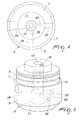
- an actuator according to the invention is generally designated by the reference numeral 1 and is substantially constituted by a fluid-actuated jack, which has an axis A and in which a cylinder is designated by the reference numeral 2 and a stem is designated by the reference numeral 3.
- the jack can be of the so-called single- or multiple-element type, i.e., composed of one or more pistons that can slide coaxially inside the cylinder 2, so as to allow the jack to extend and retract telescopically.
- the cylinder 2 has, at one end, two diametrically opposite pivots 2a and 2b, by means of which it is articulated to the fixed frame of the leaf that constitutes the skylight, and the stem 3 is articulated to the leaf so as to rotate it, when the jack is activated, between an open position and a closed position.
- the cylinder 2 is closed, at the end that lies opposite the stem 3, by a lower cap 4, which has a portion 5 that is inserted in the cylinder 2 and a portion 6 that protrudes outside the cylinder and forms a shoulder 7 for abutment against the rim of the cylinder.
- a first annular groove and a second groove are provided in the portion 5; said first annular groove accommodates a ring 8, which provides a seal against the internal wall of the cylinder 2, and a second groove for accommodating a retention ring 9 in order to fit the lower cap 4 to the cylinder.
- the lower cap 4 is crossed, along the axis A of the jack, by a hole that forms two separate seats 10 and 11, which are mutually connected by an intermediate seat 12.
- the seat 10 is open toward the inside of the cylinder 2 and is threaded so as to receive by screw coupling the threaded neck 13 of a bottle 14 that contains a pressurized gas, preferably CO 2 , in which the mouth is closed by a plug this is suitable to be pierced by an piercing element constituted by an axial pin 15 this is actuated by a mechanically-operated control device described hereinafter.
- the bottle 14 is accommodated in a compartment 2c that is formed in the cylinder 2 and is screwed until the rim of the neck 13 abuts against an internal collar 16 that divides the seat 10 from the intermediate seat 12.
- the seat 11 also is threaded and is closed by a sort of bush 17, which is screwed into it and is provided with a flange for abutment against the lower cap 4.
- the bush 17 is provided with a cavity 18, in which there is a pre-compressed spring 19, which rests with one end on the bottom of the cavity 18 and with the other end on the frustum-shaped head 20 of a shank 21 that protrudes inside the cylindrical spring 19.
- the head 20 is guided in the intermediate seat 12, and the piercing pin 15 is fixed therein, being orientated so that it is directed toward the center of the mouth of the bottle 14.
- the piercing pin 15 is tubular and is connected to a duct 22 that passes axially through the tang 12 and leads into the cavity 18 of the bush 17. In this manner, the intermediate seat 12 is constantly connected to the cavity 18 by means of the tubular pin 15 and the duct 22.
- the intermediate seat 12 is further connected to a hole 23, which extends radially from it in the portion 6 of the lower cap 4 and is connected to a cylindrical chamber 24 that is coaxial thereto in order to accommodate the flow control device.
- the hole 23 has a smaller diameter than the chamber 24, so as to form a shoulder 25 for a piston 26 that can slide within the chamber 24.
- the hole 23 accommodates a ball 27 which, when the piston 26 rests on the shoulder 25, protrudes into the seat 12, so as to act as a flow control element, which by engaging the head 20 prevents the pin 15 from being propelled against the mouth of the bottle 14 by way of the action of the spring 19.
- the piston 26 is provided with a stem 28, which is guided so that it can slide within a bush 29 that is screwed into a threaded portion of the chamber 24 and is provided with a head 30 that is external to the lower cap 4.
- a cylindrical cavity 31 is formed within the head 30 and accommodates a sensor 32 constituted by a glass vial or bulb or the like, which is adapted to break if a given temperature is exceeded.
- the condition of bulb can be inspected from the outside by means of an opening 33 for accessing the cavity 31.
- the bulb 32 is shaped so that it can be inserted into the cavity 31 through the bush 29 before said bush is screwed into the chamber 24. By screwing the bush 29, the bulb 32 pushes the piston 26 into the position in which the ball 27 protrudes into the seat 12 and prevents the sliding of the head 20.
- a radial channel 34 is formed in the portion 6 of the lower cap 4 and in a position that is angularly offset by 90° about the axis A with respect to the ball 27, and is connected on one side to the seat 11 in the region that is contiguous to the seat 12 and is closed on the opposite side by a grub screw 35.
- An additional channel 36 branches from the channel 34, runs parallel to the axis A, and leads into the compartment 2c of the cylinder 2 that accommodates the bottle 14.
- a nozzle 37 is a screwed into the outlet of the channel 36 toward the compartment 2c of the bottle 14 and forms a gauged choke 38 through which the gas of the bottle, once said bottle has been pierced, can flow out into the compartment 2c in order to activate the actuator in a controlled manner.
- a threaded seat 39 Diametrically opposite the hole 23 in the portion 6 of the lower cap 4 there is a threaded seat 39 (see Figures 4-5), which is provided radially and is designed for the screw coupling (not shown in the drawing) for connection to a compressed air source.
- the threaded seat 39 continues toward the axis A of the lower cap 4 with a hole 40 that has a square cross-section and lies on the same plane, perpendicular to the axis A, in which the channel 34 lies, and like said channel leads into the region of the seat 11 that is contiguous to the seat 12.
- a nipple 41 is screwed into the seat 39 and is crossed by an axial whole 42, which has a polygonal cross-section and in addition to acting as a compressed air passage also allows the engagement of a tool for screwing the nipple in the seat 39.
- the nipple 40 is preset to retain, against a shoulder of the seat 39, a ring 43 that surrounds an opening that is controlled by a ball 44, which constitutes the flow control element of a one-way valve that is suitable to allow the compressed air to flow only toward the seat 11.
- the ball 44 can move along a wider portion of the hole 40, so that when the bottle 14 is activated, the compressed gas that flows out of the bottle pushes the ball 44 against the ring 43 made of rubber or the like, closing the passage toward the hole 42 and diverting the flow of compressed gas towards the duct 34 and then, through the duct 36 and the choke 37, into the compartment 2c.
- the ball 44 instead moves toward the seat 11, allowing the compressed air to bleed into the hole 40 and gather in the compartment 2c.
- the actuator In the inactive condition, the actuator is in the operating condition shown in Figures 1-3, in which the flow control device (composed of the sensor 32, the piston 26 and the ball 27) engages the piercing pin 15. Accordingly, the actuator remains in the shortened position that corresponds to the passive position for keeping the leaf of the skylight closed.
- the sensor 32 When an emergency situation occurs (abnormal increase of the temperature in the environment in which the skylight is installed), the sensor 32, once it has detected the anomaly, breaks and allows the head 20, by way of the constant thrust applied thereto by the spring 19, to push back into the hole 23 the ball 27 and the piston 26 and therefore to propel the piercing pin 15 violently upward against the cap of the bottle, so as to pierce it.
- the gas that exits from the bottle 14 floods the seat 11 and then gathers, by passing through the pin 15, the duct 22, the cavity 18, the channels 34, 36 and the choke 37, in the compartment 2c of the cylinder 2, causing the activation of the actuator 1, with consequent opening of the leaf of the skylight and exit of the hot gases and smoke.
- the actuator 1 is reset by replacing the empty bottle with a full bottle.
- the lower cap 4 is removed so as to be able to unscrew the depleted bottle and replace it with a full one.
- the lower cap 4 can then be conveniently repositioned within the cylinder 2 and blocked with the aid of the retention ring 9.
- Another prerogative of the described actuator is the ability to check its efficiency from the connection of the seat 11, through the one-way valve 44, to the external source of a compressed gas (air).
- the pressure of said gas once the seat 11 is connected to the external source, has no effect on the piercing element, since the connection provided by the pin 15 and by the duct 22 between the seats 11, 12 allows to balance the pressures that exist in said seats. Accordingly, the gas, after gathering in the seat 11, can enter the channel 34 and from there, through the channel 36, the compartment 2c, so as to activate the actuator 1, checking its functionality while leaving the bottle intact.
- the described actuator perfectly achieves the intended aim and object.
- the bottle and the piercing control and actuation devices are incorporated in a single block that is associated with the cylinder 2 without having to resort to specific supports of the framework of the skylight and therefore with a considerable constructive simplification.
Landscapes
- Engineering & Computer Science (AREA)
- Physics & Mathematics (AREA)
- Fluid Mechanics (AREA)
- Mechanical Engineering (AREA)
- General Engineering & Computer Science (AREA)
- Business, Economics & Management (AREA)
- Emergency Management (AREA)
- Chemical & Material Sciences (AREA)
- Analytical Chemistry (AREA)
- Actuator (AREA)
- Portable Nailing Machines And Staplers (AREA)
- Closures For Containers (AREA)
Applications Claiming Priority (2)
| Application Number | Priority Date | Filing Date | Title |
|---|---|---|---|
| ITBO20040254 | 2004-04-23 | ||
| ITBO20040254 ITBO20040254A1 (it) | 2004-04-23 | 2004-04-23 | Attuatore in particolare per evacuatore di fumi |
Publications (2)
| Publication Number | Publication Date |
|---|---|
| EP1589231A2 true EP1589231A2 (de) | 2005-10-26 |
| EP1589231A3 EP1589231A3 (de) | 2006-01-04 |
Family
ID=34939446
Family Applications (1)
| Application Number | Title | Priority Date | Filing Date |
|---|---|---|---|
| EP05103263A Withdrawn EP1589231A3 (de) | 2004-04-23 | 2005-04-21 | Stellantrieb insbesondere für Rauchabzugsvorrichtungen. |
Country Status (2)
| Country | Link |
|---|---|
| EP (1) | EP1589231A3 (de) |
| IT (1) | ITBO20040254A1 (de) |
Cited By (4)
| Publication number | Priority date | Publication date | Assignee | Title |
|---|---|---|---|---|
| KR100813077B1 (ko) | 2007-09-21 | 2008-03-14 | 주식회사 한화 | 에어로졸 소화기용 자동작동장치 |
| EP2708830A3 (de) * | 2012-09-12 | 2015-05-13 | Erhard Rothgangl | Aktivierung einer Rauchabzugseinrichtung |
| CN113232563A (zh) * | 2021-05-25 | 2021-08-10 | 重庆长安汽车股份有限公司 | 一种车载涉水救援系统 |
| AT524492A1 (de) * | 2020-11-18 | 2022-06-15 | Grasl Pneumatic-Mechanik Gmbh | System zur belüftung und/oder zum rauch -und wärmeabzug |
Family Cites Families (3)
| Publication number | Priority date | Publication date | Assignee | Title |
|---|---|---|---|---|
| DE2408200A1 (de) * | 1974-02-20 | 1975-08-28 | Grescha Ges Grefe & Scharf | Vorrichtung zur fernbetaetigung von fluegeln von rauch- und waermeabzugsanlagen |
| DE2946244A1 (de) * | 1979-11-16 | 1981-05-21 | Batke, Bernhard, 4937 Lage | Ausloese- uns steuereinrichtung zur oeffnung und schliessung von lichtkuppeln o.dgl. |
| GB2121873A (en) * | 1982-06-16 | 1984-01-04 | Roger Graham Williams | Actuating systems for operating doors |
-
2004
- 2004-04-23 IT ITBO20040254 patent/ITBO20040254A1/it unknown
-
2005
- 2005-04-21 EP EP05103263A patent/EP1589231A3/de not_active Withdrawn
Cited By (6)
| Publication number | Priority date | Publication date | Assignee | Title |
|---|---|---|---|---|
| KR100813077B1 (ko) | 2007-09-21 | 2008-03-14 | 주식회사 한화 | 에어로졸 소화기용 자동작동장치 |
| EP2708830A3 (de) * | 2012-09-12 | 2015-05-13 | Erhard Rothgangl | Aktivierung einer Rauchabzugseinrichtung |
| AT524492A1 (de) * | 2020-11-18 | 2022-06-15 | Grasl Pneumatic-Mechanik Gmbh | System zur belüftung und/oder zum rauch -und wärmeabzug |
| AT524492B1 (de) * | 2020-11-18 | 2022-07-15 | Grasl Pneumatic-Mechanik Gmbh | System zur belüftung und/oder zum rauch -und wärmeabzug |
| CN113232563A (zh) * | 2021-05-25 | 2021-08-10 | 重庆长安汽车股份有限公司 | 一种车载涉水救援系统 |
| CN113232563B (zh) * | 2021-05-25 | 2023-03-31 | 重庆长安汽车股份有限公司 | 一种车载涉水救援系统 |
Also Published As
| Publication number | Publication date |
|---|---|
| EP1589231A3 (de) | 2006-01-04 |
| ITBO20040254A1 (it) | 2004-07-23 |
Similar Documents
| Publication | Publication Date | Title |
|---|---|---|
| US6431197B2 (en) | Regulator valve for escape slide | |
| US6209654B1 (en) | Deluge fire sprinkler system | |
| ES2537152T3 (es) | Sistema de supresión del riesgo de incendios de gas inerte con auto-modulación | |
| EP2029240B1 (de) | Rohrtrocknungs- und flutungsventil für automatische sprinklersysteme | |
| EP0511444A2 (de) | Regel- und Absperrventil | |
| EP0982519A1 (de) | Absperrventil | |
| US6491056B2 (en) | Sprinkler alarm test and drainage device for fire protection systems | |
| CN1620326B (zh) | 阀部件 | |
| TWI671613B (zh) | 氣體調節裝置 | |
| EP1589231A2 (de) | Stellantrieb insbesondere für Rauchabzugsvorrichtungen. | |
| US20040188549A1 (en) | Sprayer, in particular, a dishwashing sprayer | |
| US2764174A (en) | Quick release valves | |
| US4186766A (en) | Flow line control system | |
| JP2001340485A (ja) | 差圧式開放弁および開放式スプリンクラー設備 | |
| US5109881A (en) | Temperature sensitive control valve | |
| US10982788B2 (en) | Thermal volume control for an actuator assembly | |
| TW201510689A (zh) | 氣壓調節器 | |
| US6488049B2 (en) | Super sensitive, full flow, adjustable pressure valve | |
| US12263569B2 (en) | Gas spring-powered fastener driver | |
| EP0675254B1 (de) | Rauch- und Wärmeabzugvorrichtung, insbesondere für Notfälle | |
| NO325892B1 (no) | Vannkran | |
| US4768539A (en) | Pipeline safety valve | |
| US4304250A (en) | Flow line control system | |
| JP4276412B2 (ja) | 遮断機構付圧力調整器 | |
| US7950415B2 (en) | Coupling for self-contained breathing apparatus |
Legal Events
| Date | Code | Title | Description |
|---|---|---|---|
| PUAI | Public reference made under article 153(3) epc to a published international application that has entered the european phase |
Free format text: ORIGINAL CODE: 0009012 |
|
| AK | Designated contracting states |
Kind code of ref document: A2 Designated state(s): AT BE BG CH CY CZ DE DK EE ES FI FR GB GR HU IE IS IT LI LT LU MC NL PL PT RO SE SI SK TR |
|
| AX | Request for extension of the european patent |
Extension state: AL BA HR LV MK YU |
|
| PUAL | Search report despatched |
Free format text: ORIGINAL CODE: 0009013 |
|
| AK | Designated contracting states |
Kind code of ref document: A3 Designated state(s): AT BE BG CH CY CZ DE DK EE ES FI FR GB GR HU IE IS IT LI LT LU MC NL PL PT RO SE SI SK TR |
|
| AX | Request for extension of the european patent |
Extension state: AL BA HR LV MK YU |
|
| 17P | Request for examination filed |
Effective date: 20060703 |
|
| AKX | Designation fees paid |
Designated state(s): AT DE ES FR IT RO |
|
| GRAP | Despatch of communication of intention to grant a patent |
Free format text: ORIGINAL CODE: EPIDOSNIGR1 |
|
| STAA | Information on the status of an ep patent application or granted ep patent |
Free format text: STATUS: THE APPLICATION IS DEEMED TO BE WITHDRAWN |
|
| 18D | Application deemed to be withdrawn |
Effective date: 20071019 |