EP1589202B1 - Abgaskrümmer für Brennkraftmaschine - Google Patents
Abgaskrümmer für Brennkraftmaschine Download PDFInfo
- Publication number
- EP1589202B1 EP1589202B1 EP20050300288 EP05300288A EP1589202B1 EP 1589202 B1 EP1589202 B1 EP 1589202B1 EP 20050300288 EP20050300288 EP 20050300288 EP 05300288 A EP05300288 A EP 05300288A EP 1589202 B1 EP1589202 B1 EP 1589202B1
- Authority
- EP
- European Patent Office
- Prior art keywords
- flange
- exhaust
- inlet
- branch pipes
- exhaust manifold
- Prior art date
- Legal status (The legal status is an assumption and is not a legal conclusion. Google has not performed a legal analysis and makes no representation as to the accuracy of the status listed.)
- Expired - Lifetime
Links
Images

Classifications
-
- F—MECHANICAL ENGINEERING; LIGHTING; HEATING; WEAPONS; BLASTING
- F01—MACHINES OR ENGINES IN GENERAL; ENGINE PLANTS IN GENERAL; STEAM ENGINES
- F01N—GAS-FLOW SILENCERS OR EXHAUST APPARATUS FOR MACHINES OR ENGINES IN GENERAL; GAS-FLOW SILENCERS OR EXHAUST APPARATUS FOR INTERNAL-COMBUSTION ENGINES
- F01N13/00—Exhaust or silencing apparatus characterised by constructional features
- F01N13/08—Other arrangements or adaptations of exhaust conduits
- F01N13/10—Other arrangements or adaptations of exhaust conduits of exhaust manifolds
-
- F—MECHANICAL ENGINEERING; LIGHTING; HEATING; WEAPONS; BLASTING
- F01—MACHINES OR ENGINES IN GENERAL; ENGINE PLANTS IN GENERAL; STEAM ENGINES
- F01N—GAS-FLOW SILENCERS OR EXHAUST APPARATUS FOR MACHINES OR ENGINES IN GENERAL; GAS-FLOW SILENCERS OR EXHAUST APPARATUS FOR INTERNAL-COMBUSTION ENGINES
- F01N2260/00—Exhaust treating devices having provisions not otherwise provided for
- F01N2260/18—Exhaust treating devices having provisions not otherwise provided for for improving rigidity, e.g. by wings, ribs
-
- F—MECHANICAL ENGINEERING; LIGHTING; HEATING; WEAPONS; BLASTING
- F02—COMBUSTION ENGINES; HOT-GAS OR COMBUSTION-PRODUCT ENGINE PLANTS
- F02B—INTERNAL-COMBUSTION PISTON ENGINES; COMBUSTION ENGINES IN GENERAL
- F02B37/00—Engines characterised by provision of pumps driven at least for part of the time by exhaust
- F02B37/02—Gas passages between engine outlet and pump drive, e.g. reservoirs
Definitions
- the present invention relates to an exhaust manifold for an internal combustion engine and can in particular be used with advantage in a supercharged engine.
- the exhaust manifold serves to guide the exhaust from the cylinder head to the downstream equipment such as the turbocharger, the peripheral elements necessary for the post-treatment of the flue gases and the exhaust line (collectively called the exhaust face of the exhaust gas). engine).
- the exhaust manifold is generally equipped with several tubular conduits whose inputs are integral with a one-piece inlet flange. These ducts make it possible, from the outlet of the different exhaust pipes of the cylinder head, to direct the exhaust gases towards a single outlet integral with an outlet flange.
- the exhaust manifold is most often assembled to the cylinder head by means of a screw connection which joins the inlet flange with the exhaust face of the cylinder head.
- a metal seal is interposed between the cylinder head and the inlet flange of the exhaust manifold to provide a better seal to the exhaust gas.
- the first family of exhaust manifolds is obtained from a gravity molding process.
- the collectors are usually cast iron or steel. This family of collectors has the advantage of better control of dispersions and greater latitude in obtaining compact structures.
- Cast iron incorporating molybdenum and silicon have good casting and machinability properties. They therefore make it possible to obtain inexpensive collectors. On the other hand, the properties of these fonts are strongly altered at high temperatures. Current engines, characterized by very high flue gas temperatures, make their use often unsuitable.
- Nickel and chromium cast irons offer better hot performance than silicon and molybdenum based fonts. By cons, their less good properties of flowability and machinability generate an additional cost on the exhaust manifold.
- the second family of collectors is of the welded type.
- the manifold ducts can be obtained by stamping thin sheets, bending tubes or hydroforming.
- the materials used for the ducts are ferritic or austenitic steels.
- This family of collectors offers the possibility of designing structures of small thicknesses, thus of low inertia, and of assembling materials of different mechanical and thermophysical characteristics. Moreover, the nature of the materials makes it possible to scan a range of high temperatures. However, the corresponding manufacturing processes give rise to significant geometrical dispersions.
- the equipment upstream of the after-treatment device in particular the exhaust manifold, must be characterized by a low thermal response time.
- combustion strategies adopted to improve the efficiency of the post-treatment of flue gases especially for diesel engines, associated with specific powers up, increase the average thermal level of the exhaust gas.
- the purpose of the invention is to propose an exhaust manifold having improved resistance to thermomechanical stresses and to allow a reduction of the vibratory levels of the exhaust face of the engine, while keeping a good seal on the exhaust face of the engine between the cylinder head. and the collector.
- the invention provides an exhaust manifold as described in claim 1.
- the multiple inlet flange is disposed in the central portion of the alignment and the single inlet flanges are arranged laterally. on this alignment on either side of said multiple input flange.
- the connection pipes are in a rake form whose teeth are constituted by the ducts. inlet leading to the inter-duct transom manifold connected to the outlet duct.
- the reinforcing web is integral with the conduits and / or the cross-pipe.
- reinforcing webs also called wedges
- the presence of reinforcing webs makes it possible on the one hand to provide sufficient rigidity at the level of the lateral inter-ducts to reduce the closure of the bent parts associated with the single inlet flange ducts (by for example, the ducts of the external stations corresponding to the cylinders 1 and 4 for a manifold with four inlet ducts) and, on the other hand, to increase the section for the passage of forces at the level of the ducts corresponding to the flange of the duct.
- multiple input for example the inter-duct between the ducts of the internal stations corresponding to the cylinders 2 and 3).
- the multiple input flange and said output flange are joined to each other by a L-shaped assembly block whose branches respectively carry the outlet flange and the flange. the multiple input flange.
- the multiple input flange and said output flange are joined together by an assembly frame whose two sides are respectively carrying the output flange and the flange. multiple entry.
- the combination according to the invention of a reduction of the rigidity at the level of all the inlet flanges and of a connection with high rigidity between a multiple inlet flange (breech side) and the flange of exit (exhaust side) reduces the risk of thermomechanical fatigue cracking and improves the overall dynamic behavior.
- the performance of a collector according to the invention is further increased with the addition of wedges at the collector inter-ducts.
- the invention is directly applicable to both types of collectors, the collectors obtained by gravity molding and the mechanically welded collectors.
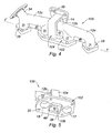
- FIGS. Figures 1 to 5 a three-dimensional system with perpendicular planes Pxy, Pxz, and Pyz defined with respect to Figures 1 to 3 .
- the collector 10 is represented in figure 2 in longitudinal section cut along the plane Pyz with a rotation along the axis ZZ 'of 90 ° and represented in figure 3 in cross section cut along the plane Pxz with rotation along the axis ZZ 'of 180 ° and the collector 100 is shown in FIG. figure 4 with a rotation along the axis ZZ 'of 90 ° with respect to the figure 1 and represented at figure 5 with a rotation according to YY 'of 90 ° with respect to figure 4 .
- the exhaust manifold 10 for a multicylinder internal combustion engine illustrated in FIGS. Figures 1, 2 and 3 relates to a first embodiment of the invention given solely by way of non-limiting example, in this case a manifold intended to be associated with an in-line four cylinder cylinder (not shown) or a multiple cylinder head having several groups four cylinders in line for example a motor cylinder head V8 (not shown) which will then be equipped with two collectors according to the invention.
- the collector 10 as illustrated is made of a mechanically welded structure but can without departing from the scope of the invention be obtained by molding cast iron or steel, the invention being advantageously applicable to both manufacturing techniques, molding and tack welding.
- the collector 10 essentially comprises connection pipes made of thin steel sheets of generally rake form, the teeth of which consist of the ducts 21, inlet ducts 22, 23 and 24 of the inlet ends of the gases substantially aligned along an axis.
- YY ' the collector further having a general structure almost symmetrical with respect to the median plane Pxz perpendicular to the axis YY'.
- the ducts 21-24 have an orientation along the axis ZZ 'and lead to a crosspiece pipe 12 extending substantially parallel to the axis YY' to define three inter-ducts 12a, 12b and 12c.
- the tubing 12 is slightly bent in its inverted V medium in the Pyz plane at the height of the inter-ducts 12b as shown in FIG.
- the manifold manifolds also have an outlet end having a gas outlet duct 14 extending substantially parallel to the axis XX 'and disposed symmetrically with respect to the median plane Pxz and opening into the central duct 12b.
- the outlet duct 14 carries an outlet flange 38 of the exhaust gas suitably connected by a downstream exhaust pipe to the downstream equipment (not shown) such as turbocharger, peripheral elements for aftertreatment of the flue gas and exhaust line.
- the trapezoidal generally trapezoidal flange 38 formed from a plate or steel soleplate has a large central through opening 37 on which is welded the wall of the duct 14 as illustrated on FIG. figure 3 .
- three mounting openings 32 are provided in the flange 38 at the legs 42 (small base) and 41 (wide base) to allow mounting and connection with a downstream exhaust pipe (not shown).
- the inlet ends constituted by the ducts 21 to 24 are distributed in free ends, in this case the external inlet ducts 21 and 24 each carrying a fastening flange 26 and 28. , and ends joined together around a multiple flange, in this case the central double flange 30 to which are associated the inner inlet ducts 22 and 23.
- the three flanges 26, 28 and 30 obtained from plates or steel soles have through openings of large diameter 16, 17, 18, 19 on which are welded the walls of the corresponding inlet ducts 21 to 24.
- three flanges are separated from each other and have free faces 27, 29, 31 extending in the plane Pxy.
- the flanges 26, 28 and 30 have through openings 32 of reduced diameter through which the rods of the wide-headed fastening bolts (not shown) screwed into threaded bores in the cylinder head of the engine receiving the
- the flanges 26, 28 and 30 are mounted on the exhaust face of the cylinder head with the interposition of metal sealing joints so as to separately connect each inlet duct 21 to 24 to the corresponding four corresponding exhaust openings. on the breech.
- the inter-ducts 12c communicate with a recirculation duct 34 carrying a flange 36 (similar to the simple flanges 26 and 28) intended to be connected to a recirculation circuit (not shown) of the exhaust gases to the intake duct of the engine cylinders (recirculation circuit also called EGR circuit and intended to reduce the emissions of gaseous pollutants, including NO and NO 2 ).
- a recirculation circuit also called EGR circuit and intended to reduce the emissions of gaseous pollutants, including NO and NO 2 ).
- the multiple input flange 30 is secured to the outlet flange 38 carried by the outlet duct 14 in order to improve the structural rigidity of the collector.
- This configuration can be achieved with a molding process on cast iron or cast steel structures.
- the connection between the two flanges is obtained through a screwed or welded assembly, the latter method being the least expensive.
- This bonding makes it possible to improve the dynamic behavior of the collector, in particular with regard to the mechanical resonances of the motor assembly incorporating the collector.
- this connection makes it possible to limit the thermomechanical and dynamic stresses at the junction between the outlet flange and the inlet ducts.
- the set of inlet and outlet flanges 38 of the manifold 10 form an L-shaped assembly block as shown in FIGS. Figures 1 and 3 in which the small width tab 42 of the flange 38 is welded to the middle portion 44 of the double flange 30, which connection may or may not be stiffened by one or more brackets at the base of the junction of the two flanges 30 and 38 ( in this case there are two brackets 46, on either side of the fixing opening 39 made in the tab 42, and only one is visible on the Figures 1 and 3 ).
- Another more rigid frame block structure in the form of a frame and illustrated in FIGS. Figures 4 and 5 will be described hereinafter with reference to the collector 100.
- the ducts of at least two adjacent inlet ends are interconnected by a reinforcing web.
- the reinforcing web is integral with the conduits and the inter-ducts of the cross-pipe.
- the collector 10 has reinforcing webs 48, 49, 50 on each of the inter-ducts 12a, 12b, 12c.
- the webs consist of two contiguous sheets integrally formed with the adjacent inter-ducts (12b) and welded together and to the inlet ducts (22). and 23).
- the collector 10 of welded half-shell type the webs are obtained directly by stamping.
- the reinforcement sails are obtained by welding flat products.
- the reinforcing webs are made of material with the cross-pipe and the corresponding inlet ducts and obtained directly at casting.
- reinforcement veils also called wedges
- the increase of the resistance section with respect to the forces at the level of the inter-ducts 12a and 12c makes it possible to reduce the stresses associated with compressive membrane stresses.
- the increase of the bending stiffness makes it possible, on the one hand, to reduce the closure of the bent parts associated with the single inlet flange ducts 21 and 24 in the outer position (bending caused by the friction forces at the collecting interface and breech and by the expansion at the inter-duct 12b) and secondly to improve the sealing of the collector interface / breech at the separate flanges 26, 28.
- the solicitations are predominantly of membrane type and essentially related to the expansions thwarted by the multiple input flange 30.
- the reinforcing web 49 increases the bending stiffness of the inter-duct 12b, l addition of this decoupled web of the multiple flange 30, for the most part, reduces the compressive thermomechanical membrane stresses.
- the Figures 4 and 5 are perspective views of a second embodiment of an exhaust manifold according to the invention 100.
- the collector 100 is very close to the collector 10 which it represents, in fact, an interesting variant in terms of the robustness of the connection between the multiple input flange and the output flange.
- the collector 100 comprises, with two exceptions (the replacement of the double flange 30 by the double flange 102, and the addition of the spacer 104), the same elements as those of the collector 10 and mounted in a quasi-identical configuration. identical to that of the collector 10.
- the exhaust manifold 100 differs from the manifold 10 by a structural modification, namely the strengthening of the connection between the central multiple inlet flange 102 and the outlet flange 38 by the addition of an L-shaped spacer 104 welded between the middle portion of the multiple flange 102 and the wide tab 41 of the outlet flange 38.
- the assembly block solarizing the multiple input flange 102 and the output flange 38 is presented in the form of an assembly frame of rectangular structure of which two sides are respectively carrying the output flange 38 and the multiple input flange 102 and the other two sides are constituted by the L-shaped spacer 104.
- the multiple inlet flange 102 is in the form of an elongated sole provided with two openings 17 and 18 associated with the two inner inlet ducts 22 and 23 disposed on either side of a central through opening.
- 106 disposed to the right of the outlet flange 38 to limit the resistant section of the double inlet flange 102 at the central inter-duct 12b.
- the invention is not limited to the exhaust manifolds described but also covers various variants in which in particular the position of the multiple inlet flange can be modified with respect to the central position described above with reference to the collectors 10 and 100 and / or the orientation of the outlet flange with respect to the multiple inlet flange (described at about 90 ° for the collectors 10 and 100) can be modified for example to 180 ° with in particular the use of a U-shaped piece spanning the inter-duct 12b and welded to the flange 102.
- the invention is not limited to exhaust manifolds having 4 inlet ducts but also covers, for example, manifolds with 3, 5 and 6 ducts in which two ducts are secured to a double inlet flange which is itself secured. at the outlet flange, the other ducts being associated with separate flanges.
Landscapes
- Engineering & Computer Science (AREA)
- Chemical & Material Sciences (AREA)
- Combustion & Propulsion (AREA)
- Mechanical Engineering (AREA)
- General Engineering & Computer Science (AREA)
- Exhaust Silencers (AREA)
- Cylinder Crankcases Of Internal Combustion Engines (AREA)
Claims (10)
- Auspuffkrümmer (10, 100) für einen Mehrzylinder-Verbrennungsmotor, der miteinander verbundene Anschlussrohrstutzen aufweist, darunter einen Querträger-Rohrstutzen (12), in den münden- eine Vielzahl von Eingangskanälen (21, 22, 23, 24), im Wesentlichen fluchtend ausgerichtet und dazu bestimmt, an Auspufföffnungen des Zylinderkopfs des Motors angeschlossen zu werden, und- ein Ausgangskanal (14), der dazu bestimmt ist, an einen Abgaskanal angeschlossen zu werden, wobei die Eingangskanäle (21, 22, 23, 24) in Kanäle mit freien Enden (21, 24), die je einen einfachen Eingangsflansch (26, 28) tragen, und in Kanäle mit durch mindestens einen Mehrfach-Eingangsflansch (30, 102) fest verbundenen Enden (22, 23) aufgeteilt sind, der von den Kanälen mit fest verbundene Enden getragen wird, wobei die einfachen und/oder Mehrfach-Eingangsflansche (26, 28, 30, 102) dazu bestimmt sind, mit den Auspufföffnungen verbunden zu werden und voneinander getrennt sind,wobei mindestens ein Mehrfach-Eingangsflansch (30, 102) fest mit einem Ausgangsflansch (38) verbunden ist, der von dem Ausgangskanal (14) des Krümmers getragen wird, und
wobei mindestens zwei benachbarte Eingangskanäle (21-22, 22-23, 23-24) durch eine Verstärkungsmembran (48, 49, 50) miteinander verbunden sind,
dadurch gekennzeichnet, dass die Verstärkungsmembran (48, 49, 50) ebenfalls die zwei benachbarten Kanäle (21-22, 22-23, 23-24) mit dem Querträger-Rohrstutzen (12) verbindet. - Auspuffkrümmer nach Anspruch 1, dadurch gekennzeichnet, dass die Verstärkungsmembran (48, 49, 50) aus dem gleichen Material besteht wie die Eingangskanäle (21-22, 22-23, 23-24) und/oder der Querträger-Rohrstutzen (12).
- Auspuffkrümmer nach einem der Ansprüche 1 und 2, dadurch gekennzeichnet, dass die Anschlussrohrstutzen in Form eines Rechens vorliegen, dessen Zinken aus den Eingangskanälen (21, 22, 23, 24) bestehen, die auf dem Zwischenkanal-Querträger-Rohrstutzen (12a, 12b, 12c) münden, der mit dem Ausgangsende verbunden ist.
- Auspuffkrümmer nach einem der vorhergehenden Ansprüche, dadurch gekennzeichnet, dass der Mehrfach-Eingangsflansch (30) und der Ausgangsflansch (38) durch einen L-förmigen Montageblock fest miteinander verbunden sind, dessen Schenkel den Ausgangsflansch (38) bzw. den Mehrfach-Eingangsflansch (30) tragen.
- Auspuffkrümmer nach einem der Ansprüche 1 bis 3, dadurch gekennzeichnet, dass der Mehrfach-Eingangsflansch (102) und der Ausgangsflansch (38) durch einen Montagerahmen fest miteinander verbunden sind, dessen zwei Seiten den Ausgangsflansch (38) bzw. den Mehrfach-Eingangsflansch (102) tragen.
- Auspuffkrümmer nach einem der vorhergehenden Ansprüche, dadurch gekennzeichnet, dass der Mehrfach-Eingangsflansch (30, 102) zwei Eingangsenden (22, 23) fest miteinander verbindet, und dass der Ausgangsflansch (38) bezüglich des Mehrfach-Eingangsflanschs (30, 102) zwischen den zwei Eingangsenden (22, 23) angeordnet ist.
- Auspuffkrümmer nach Anspruch 6, dadurch gekennzeichnet, dass der Mehrfach-Eingangsflansch (102) in Form einer länglichen Grundplatte vorliegt, die mit zwei den zwei Eingangsenden (22, 23) zugeordneten Öffnungen (17, 18) versehen ist, die zu beiden Seiten einer zentralen Öffnung (106) angeordnet sind, die sich im rechten Winkel vor dem Ausgangsflansch (38) befindet.
- Krümmer nach einem der Ansprüche 6 und 7, dadurch gekennzeichnet, dass der Ausgangsflansch (38) im Wesentlichen lotrecht zum Mehrfach-Eingangsflansch (30, 102) angeordnet ist.
- Auspuffkrümmer nach einem der vorhergehenden Ansprüche, dadurch gekennzeichnet, dass der Mehrfach-Eingangsflansch (30, 102) im zentralen Bereich der fluchtenden Anordnung angeordnet ist, und dass die einfachen Eingangsflansche (26, 28) seitlich auf der fluchtenden Anordnung zu beiden Seiten des Mehrfach-Eingangsflanschs (30, 102) angeordnet sind.
- Auspuffkrümmer nach einem der vorhergehenden Ansprüche, dadurch gekennzeichnet, dass er vier Eingangskanäle (21, 22, 23, 24) aufweist, die auf zwei Kanäle mit durch einen Mehrfach-Eingangsflansch (30, 102) fest verbundenen Enden (22, 23) aufgeteilt sind, die zwischen zwei Kanälen mit freien Enden (21, 24) angeordnet sind.
Applications Claiming Priority (2)
| Application Number | Priority Date | Filing Date | Title |
|---|---|---|---|
| FR0404274 | 2004-04-22 | ||
| FR0404274A FR2869352B1 (fr) | 2004-04-22 | 2004-04-22 | Collecteur d'echappement pour moteur a combustion interne |
Publications (2)
| Publication Number | Publication Date |
|---|---|
| EP1589202A1 EP1589202A1 (de) | 2005-10-26 |
| EP1589202B1 true EP1589202B1 (de) | 2012-06-20 |
Family
ID=34942550
Family Applications (1)
| Application Number | Title | Priority Date | Filing Date |
|---|---|---|---|
| EP20050300288 Expired - Lifetime EP1589202B1 (de) | 2004-04-22 | 2005-04-19 | Abgaskrümmer für Brennkraftmaschine |
Country Status (2)
| Country | Link |
|---|---|
| EP (1) | EP1589202B1 (de) |
| FR (1) | FR2869352B1 (de) |
Families Citing this family (5)
| Publication number | Priority date | Publication date | Assignee | Title |
|---|---|---|---|---|
| DE102004054726A1 (de) | 2004-11-12 | 2006-06-08 | Daimlerchrysler Ag | Aufgeladene Brennkraftmaschine |
| DE102008063744A1 (de) | 2008-12-18 | 2010-07-08 | Friedrich Boysen Gmbh & Co. Kg | Einwandkrümmer |
| CN104533586A (zh) * | 2014-12-25 | 2015-04-22 | 江铃汽车股份有限公司 | 一种高排温汽油机的排气歧管结构 |
| CN106285888A (zh) * | 2016-08-31 | 2017-01-04 | 芜湖恒耀汽车零部件有限公司 | 汽车排气歧管 |
| CN113339122B (zh) * | 2021-06-28 | 2022-12-13 | 一汽解放汽车有限公司 | 排气歧管及动力系统 |
Family Cites Families (5)
| Publication number | Priority date | Publication date | Assignee | Title |
|---|---|---|---|---|
| US4514986A (en) * | 1983-07-18 | 1985-05-07 | Benson Steven R | Double-chambered exhaust manifold |
| US4777708A (en) * | 1987-03-17 | 1988-10-18 | Ap Industries, Inc. | Method for manufacturing an exhaust manifold |
| FR2801072B1 (fr) * | 1999-11-17 | 2002-11-08 | Renault | Turbocompresseur comportant des entrees de turbine alignees selon un plan radial |
| DE10102637A1 (de) * | 2001-01-20 | 2002-07-25 | Bayerische Motoren Werke Ag | Abgaskrümmer zur Abgasabführung aus einem Verbrennungsmotor |
| SE0101451L (sv) * | 2001-04-26 | 2002-04-09 | Press & Plaatindustri Ab | Grenrör |
-
2004
- 2004-04-22 FR FR0404274A patent/FR2869352B1/fr not_active Expired - Fee Related
-
2005
- 2005-04-19 EP EP20050300288 patent/EP1589202B1/de not_active Expired - Lifetime
Also Published As
| Publication number | Publication date |
|---|---|
| FR2869352B1 (fr) | 2008-07-18 |
| EP1589202A1 (de) | 2005-10-26 |
| FR2869352A1 (fr) | 2005-10-28 |
Similar Documents
| Publication | Publication Date | Title |
|---|---|---|
| EP2012061B2 (de) | Brennkammer eines Gasturbinentriebwerks | |
| FR2942846A1 (fr) | Sous-ensemble d'echappement | |
| EP2502016B1 (de) | Wärmetauscher für gase, im besonderen für motorabgase | |
| EP1527308B1 (de) | Wärmetauscher für den verbrennungsluftkreislauf eines thermischen motors | |
| FR2931517A1 (fr) | Dispositif d'admission de gaz | |
| WO2008061850A1 (fr) | Dispositif d'echange de chaleur et dispositif d'admission de gaz comportant un tel dispositif | |
| EP1589202B1 (de) | Abgaskrümmer für Brennkraftmaschine | |
| EP1557553B1 (de) | Einblockarm für eine Nachverbrennungsvorrichtung eines Triebwerkes mit Doppelströmung | |
| FR2870886A1 (fr) | Collecteur de gaz d'echappement de moteur a combustion interne | |
| FR2837877A1 (fr) | Modele de superstatoreacteur | |
| JP3497443B2 (ja) | 車両におけるエンジンの排気装置 | |
| FR2875266A1 (fr) | Collecteur d'echappement pour moteur a combustion interne | |
| FR3071777A1 (fr) | Structure de fixation de refroidisseur intermediaire de vehicule | |
| FR2849470A1 (fr) | Collecteur d'echappement de vehicule automobile a structure porteuse independante | |
| WO2011029940A1 (fr) | Échangeur de chaleur pour gaz, particulièrement pour les gaz d'échappement d'un moteur | |
| FR2870289A1 (fr) | Collecteur d'echappement pour moteur a combustion interne | |
| EP2722517B2 (de) | Ansaugmodul in Gestalt eines Ansaugkrümmers mit integriertem Wärmetauscher | |
| EP3449198B1 (de) | Sammler und zugehörige kühlvorrichtung | |
| EP1780386A1 (de) | Eingangsflansch eines gebogenen Rohres eines Abgaskrümmers und Brennkraftmaschine mit einem solchen Flansch | |
| EP3959479B1 (de) | Wärmetauscher mit sicherung der befestigung an der sammlerecke | |
| FR2989729A1 (fr) | Collecteur d'echappement twin scroll pour moteur a combustion interne | |
| FR2877694A1 (fr) | Tuyau d'echappement et procede pour la fabrication d'un tuyau d'echappement | |
| FR3138940A1 (fr) | Echangeur de chaleur surfacique pour nacelle d’une turbomachine et nacelle de turbomachine équipée d’un tel échangeur de chaleur | |
| FR2908821A1 (fr) | Ensemble collecteur d'echappement/culasse pour moteur a combustion interne | |
| FR2930288A1 (fr) | Ensemble collecteur de ligne d'echappement comprenant un collecteur et un boitier. |
Legal Events
| Date | Code | Title | Description |
|---|---|---|---|
| PUAI | Public reference made under article 153(3) epc to a published international application that has entered the european phase |
Free format text: ORIGINAL CODE: 0009012 |
|
| AK | Designated contracting states |
Kind code of ref document: A1 Designated state(s): AT BE BG CH CY CZ DE DK EE ES FI FR GB GR HU IE IS IT LI LT LU MC NL PL PT RO SE SI SK TR |
|
| AX | Request for extension of the european patent |
Extension state: AL BA HR LV MK YU |
|
| 17P | Request for examination filed |
Effective date: 20060113 |
|
| AKX | Designation fees paid |
Designated state(s): AT BE BG CH CY CZ DE DK EE ES FI FR GB GR HU IE IS IT LI LT LU MC NL PL PT RO SE SI SK TR |
|
| 17Q | First examination report despatched |
Effective date: 20081016 |
|
| GRAP | Despatch of communication of intention to grant a patent |
Free format text: ORIGINAL CODE: EPIDOSNIGR1 |
|
| RIN1 | Information on inventor provided before grant (corrected) |
Inventor name: RAGOT, PATRICK |
|
| GRAS | Grant fee paid |
Free format text: ORIGINAL CODE: EPIDOSNIGR3 |
|
| GRAA | (expected) grant |
Free format text: ORIGINAL CODE: 0009210 |
|
| AK | Designated contracting states |
Kind code of ref document: B1 Designated state(s): AT BE BG CH CY CZ DE DK EE ES FI FR GB GR HU IE IS IT LI LT LU MC NL PL PT RO SE SI SK TR |
|
| REG | Reference to a national code |
Ref country code: GB Ref legal event code: FG4D Free format text: NOT ENGLISH |
|
| REG | Reference to a national code |
Ref country code: CH Ref legal event code: EP |
|
| REG | Reference to a national code |
Ref country code: AT Ref legal event code: REF Ref document number: 563206 Country of ref document: AT Kind code of ref document: T Effective date: 20120715 |
|
| REG | Reference to a national code |
Ref country code: IE Ref legal event code: FG4D Free format text: LANGUAGE OF EP DOCUMENT: FRENCH |
|
| REG | Reference to a national code |
Ref country code: DE Ref legal event code: R096 Ref document number: 602005034819 Country of ref document: DE Effective date: 20120816 |
|
| PG25 | Lapsed in a contracting state [announced via postgrant information from national office to epo] |
Ref country code: FI Free format text: LAPSE BECAUSE OF FAILURE TO SUBMIT A TRANSLATION OF THE DESCRIPTION OR TO PAY THE FEE WITHIN THE PRESCRIBED TIME-LIMIT Effective date: 20120620 Ref country code: SE Free format text: LAPSE BECAUSE OF FAILURE TO SUBMIT A TRANSLATION OF THE DESCRIPTION OR TO PAY THE FEE WITHIN THE PRESCRIBED TIME-LIMIT Effective date: 20120620 Ref country code: LT Free format text: LAPSE BECAUSE OF FAILURE TO SUBMIT A TRANSLATION OF THE DESCRIPTION OR TO PAY THE FEE WITHIN THE PRESCRIBED TIME-LIMIT Effective date: 20120620 |
|
| REG | Reference to a national code |
Ref country code: NL Ref legal event code: VDEP Effective date: 20120620 |
|
| REG | Reference to a national code |
Ref country code: AT Ref legal event code: MK05 Ref document number: 563206 Country of ref document: AT Kind code of ref document: T Effective date: 20120620 |
|
| REG | Reference to a national code |
Ref country code: LT Ref legal event code: MG4D Effective date: 20120606 |
|
| PG25 | Lapsed in a contracting state [announced via postgrant information from national office to epo] |
Ref country code: SI Free format text: LAPSE BECAUSE OF FAILURE TO SUBMIT A TRANSLATION OF THE DESCRIPTION OR TO PAY THE FEE WITHIN THE PRESCRIBED TIME-LIMIT Effective date: 20120620 Ref country code: GR Free format text: LAPSE BECAUSE OF FAILURE TO SUBMIT A TRANSLATION OF THE DESCRIPTION OR TO PAY THE FEE WITHIN THE PRESCRIBED TIME-LIMIT Effective date: 20120921 |
|
| PG25 | Lapsed in a contracting state [announced via postgrant information from national office to epo] |
Ref country code: AT Free format text: LAPSE BECAUSE OF FAILURE TO SUBMIT A TRANSLATION OF THE DESCRIPTION OR TO PAY THE FEE WITHIN THE PRESCRIBED TIME-LIMIT Effective date: 20120620 Ref country code: SK Free format text: LAPSE BECAUSE OF FAILURE TO SUBMIT A TRANSLATION OF THE DESCRIPTION OR TO PAY THE FEE WITHIN THE PRESCRIBED TIME-LIMIT Effective date: 20120620 Ref country code: CY Free format text: LAPSE BECAUSE OF FAILURE TO SUBMIT A TRANSLATION OF THE DESCRIPTION OR TO PAY THE FEE WITHIN THE PRESCRIBED TIME-LIMIT Effective date: 20120620 Ref country code: IS Free format text: LAPSE BECAUSE OF FAILURE TO SUBMIT A TRANSLATION OF THE DESCRIPTION OR TO PAY THE FEE WITHIN THE PRESCRIBED TIME-LIMIT Effective date: 20121020 Ref country code: CZ Free format text: LAPSE BECAUSE OF FAILURE TO SUBMIT A TRANSLATION OF THE DESCRIPTION OR TO PAY THE FEE WITHIN THE PRESCRIBED TIME-LIMIT Effective date: 20120620 Ref country code: RO Free format text: LAPSE BECAUSE OF FAILURE TO SUBMIT A TRANSLATION OF THE DESCRIPTION OR TO PAY THE FEE WITHIN THE PRESCRIBED TIME-LIMIT Effective date: 20120620 Ref country code: EE Free format text: LAPSE BECAUSE OF FAILURE TO SUBMIT A TRANSLATION OF THE DESCRIPTION OR TO PAY THE FEE WITHIN THE PRESCRIBED TIME-LIMIT Effective date: 20120620 |
|
| PG25 | Lapsed in a contracting state [announced via postgrant information from national office to epo] |
Ref country code: PL Free format text: LAPSE BECAUSE OF FAILURE TO SUBMIT A TRANSLATION OF THE DESCRIPTION OR TO PAY THE FEE WITHIN THE PRESCRIBED TIME-LIMIT Effective date: 20120620 Ref country code: PT Free format text: LAPSE BECAUSE OF FAILURE TO SUBMIT A TRANSLATION OF THE DESCRIPTION OR TO PAY THE FEE WITHIN THE PRESCRIBED TIME-LIMIT Effective date: 20121022 Ref country code: IT Free format text: LAPSE BECAUSE OF FAILURE TO SUBMIT A TRANSLATION OF THE DESCRIPTION OR TO PAY THE FEE WITHIN THE PRESCRIBED TIME-LIMIT Effective date: 20120620 |
|
| PG25 | Lapsed in a contracting state [announced via postgrant information from national office to epo] |
Ref country code: NL Free format text: LAPSE BECAUSE OF FAILURE TO SUBMIT A TRANSLATION OF THE DESCRIPTION OR TO PAY THE FEE WITHIN THE PRESCRIBED TIME-LIMIT Effective date: 20120620 |
|
| PLBE | No opposition filed within time limit |
Free format text: ORIGINAL CODE: 0009261 |
|
| STAA | Information on the status of an ep patent application or granted ep patent |
Free format text: STATUS: NO OPPOSITION FILED WITHIN TIME LIMIT |
|
| PG25 | Lapsed in a contracting state [announced via postgrant information from national office to epo] |
Ref country code: DK Free format text: LAPSE BECAUSE OF FAILURE TO SUBMIT A TRANSLATION OF THE DESCRIPTION OR TO PAY THE FEE WITHIN THE PRESCRIBED TIME-LIMIT Effective date: 20120620 |
|
| 26N | No opposition filed |
Effective date: 20130321 |
|
| REG | Reference to a national code |
Ref country code: DE Ref legal event code: R097 Ref document number: 602005034819 Country of ref document: DE Effective date: 20130321 |
|
| PG25 | Lapsed in a contracting state [announced via postgrant information from national office to epo] |
Ref country code: BG Free format text: LAPSE BECAUSE OF FAILURE TO SUBMIT A TRANSLATION OF THE DESCRIPTION OR TO PAY THE FEE WITHIN THE PRESCRIBED TIME-LIMIT Effective date: 20120920 |
|
| BERE | Be: lapsed |
Owner name: RENAULT S.A.S. Effective date: 20130430 |
|
| PG25 | Lapsed in a contracting state [announced via postgrant information from national office to epo] |
Ref country code: ES Free format text: LAPSE BECAUSE OF FAILURE TO SUBMIT A TRANSLATION OF THE DESCRIPTION OR TO PAY THE FEE WITHIN THE PRESCRIBED TIME-LIMIT Effective date: 20121001 |
|
| PG25 | Lapsed in a contracting state [announced via postgrant information from national office to epo] |
Ref country code: MC Free format text: LAPSE BECAUSE OF FAILURE TO SUBMIT A TRANSLATION OF THE DESCRIPTION OR TO PAY THE FEE WITHIN THE PRESCRIBED TIME-LIMIT Effective date: 20120620 |
|
| REG | Reference to a national code |
Ref country code: CH Ref legal event code: PL |
|
| REG | Reference to a national code |
Ref country code: IE Ref legal event code: MM4A |
|
| PG25 | Lapsed in a contracting state [announced via postgrant information from national office to epo] |
Ref country code: LI Free format text: LAPSE BECAUSE OF NON-PAYMENT OF DUE FEES Effective date: 20130430 Ref country code: BE Free format text: LAPSE BECAUSE OF NON-PAYMENT OF DUE FEES Effective date: 20130430 Ref country code: CH Free format text: LAPSE BECAUSE OF NON-PAYMENT OF DUE FEES Effective date: 20130430 |
|
| PG25 | Lapsed in a contracting state [announced via postgrant information from national office to epo] |
Ref country code: IE Free format text: LAPSE BECAUSE OF NON-PAYMENT OF DUE FEES Effective date: 20130419 |
|
| REG | Reference to a national code |
Ref country code: FR Ref legal event code: PLFP Year of fee payment: 11 |
|
| PG25 | Lapsed in a contracting state [announced via postgrant information from national office to epo] |
Ref country code: TR Free format text: LAPSE BECAUSE OF FAILURE TO SUBMIT A TRANSLATION OF THE DESCRIPTION OR TO PAY THE FEE WITHIN THE PRESCRIBED TIME-LIMIT Effective date: 20120620 |
|
| PG25 | Lapsed in a contracting state [announced via postgrant information from national office to epo] |
Ref country code: HU Free format text: LAPSE BECAUSE OF FAILURE TO SUBMIT A TRANSLATION OF THE DESCRIPTION OR TO PAY THE FEE WITHIN THE PRESCRIBED TIME-LIMIT; INVALID AB INITIO Effective date: 20050419 Ref country code: LU Free format text: LAPSE BECAUSE OF NON-PAYMENT OF DUE FEES Effective date: 20130419 |
|
| REG | Reference to a national code |
Ref country code: FR Ref legal event code: PLFP Year of fee payment: 12 |
|
| PGFP | Annual fee paid to national office [announced via postgrant information from national office to epo] |
Ref country code: DE Payment date: 20160421 Year of fee payment: 12 Ref country code: GB Payment date: 20160421 Year of fee payment: 12 |
|
| PGFP | Annual fee paid to national office [announced via postgrant information from national office to epo] |
Ref country code: FR Payment date: 20160421 Year of fee payment: 12 |
|
| REG | Reference to a national code |
Ref country code: DE Ref legal event code: R119 Ref document number: 602005034819 Country of ref document: DE |
|
| GBPC | Gb: european patent ceased through non-payment of renewal fee |
Effective date: 20170419 |
|
| REG | Reference to a national code |
Ref country code: FR Ref legal event code: ST Effective date: 20171229 |
|
| PG25 | Lapsed in a contracting state [announced via postgrant information from national office to epo] |
Ref country code: DE Free format text: LAPSE BECAUSE OF NON-PAYMENT OF DUE FEES Effective date: 20171103 Ref country code: FR Free format text: LAPSE BECAUSE OF NON-PAYMENT OF DUE FEES Effective date: 20170502 |
|
| PG25 | Lapsed in a contracting state [announced via postgrant information from national office to epo] |
Ref country code: GB Free format text: LAPSE BECAUSE OF NON-PAYMENT OF DUE FEES Effective date: 20170419 |