EP1589163A1 - Anker zum Kippen und Heben eines Paneels aus härtbarem Material, insbesondere Beton - Google Patents
Anker zum Kippen und Heben eines Paneels aus härtbarem Material, insbesondere Beton Download PDFInfo
- Publication number
- EP1589163A1 EP1589163A1 EP04291029A EP04291029A EP1589163A1 EP 1589163 A1 EP1589163 A1 EP 1589163A1 EP 04291029 A EP04291029 A EP 04291029A EP 04291029 A EP04291029 A EP 04291029A EP 1589163 A1 EP1589163 A1 EP 1589163A1
- Authority
- EP
- European Patent Office
- Prior art keywords
- wings
- rod
- anchor
- oblique
- boss
- Prior art date
- Legal status (The legal status is an assumption and is not a legal conclusion. Google has not performed a legal analysis and makes no representation as to the accuracy of the status listed.)
- Granted
Links
- 239000004567 concrete Substances 0.000 title claims description 13
- 239000000463 material Substances 0.000 title claims description 8
- 238000004873 anchoring Methods 0.000 claims abstract description 7
- 230000003247 decreasing effect Effects 0.000 claims description 5
- 235000014571 nuts Nutrition 0.000 description 11
- 244000245420 ail Species 0.000 description 10
- 230000006835 compression Effects 0.000 description 10
- 238000007906 compression Methods 0.000 description 10
- 208000029152 Small face Diseases 0.000 description 7
- 229910000831 Steel Inorganic materials 0.000 description 2
- 210000004027 cell Anatomy 0.000 description 2
- 238000005336 cracking Methods 0.000 description 2
- 239000010959 steel Substances 0.000 description 2
- 240000007049 Juglans regia Species 0.000 description 1
- 235000009496 Juglans regia Nutrition 0.000 description 1
- 239000004568 cement Substances 0.000 description 1
- 230000001186 cumulative effect Effects 0.000 description 1
- 238000009826 distribution Methods 0.000 description 1
- 230000000694 effects Effects 0.000 description 1
- 238000005242 forging Methods 0.000 description 1
- 235000000396 iron Nutrition 0.000 description 1
- 238000004519 manufacturing process Methods 0.000 description 1
- 239000002184 metal Substances 0.000 description 1
- 238000000034 method Methods 0.000 description 1
- 230000004048 modification Effects 0.000 description 1
- 238000012986 modification Methods 0.000 description 1
- 238000005457 optimization Methods 0.000 description 1
- 239000011505 plaster Substances 0.000 description 1
- 229920003023 plastic Polymers 0.000 description 1
- 239000004033 plastic Substances 0.000 description 1
- 239000011178 precast concrete Substances 0.000 description 1
- 238000004080 punching Methods 0.000 description 1
- 230000002787 reinforcement Effects 0.000 description 1
- 229920005989 resin Polymers 0.000 description 1
- 239000011347 resin Substances 0.000 description 1
- 239000007787 solid Substances 0.000 description 1
- 239000000725 suspension Substances 0.000 description 1
- 230000007704 transition Effects 0.000 description 1
- 235000020234 walnut Nutrition 0.000 description 1
Images



Classifications
-
- B—PERFORMING OPERATIONS; TRANSPORTING
- B66—HOISTING; LIFTING; HAULING
- B66C—CRANES; LOAD-ENGAGING ELEMENTS OR DEVICES FOR CRANES, CAPSTANS, WINCHES, OR TACKLES
- B66C1/00—Load-engaging elements or devices attached to lifting or lowering gear of cranes or adapted for connection therewith for transmitting lifting forces to articles or groups of articles
- B66C1/10—Load-engaging elements or devices attached to lifting or lowering gear of cranes or adapted for connection therewith for transmitting lifting forces to articles or groups of articles by mechanical means
- B66C1/62—Load-engaging elements or devices attached to lifting or lowering gear of cranes or adapted for connection therewith for transmitting lifting forces to articles or groups of articles by mechanical means comprising article-engaging members of a shape complementary to that of the articles to be handled
- B66C1/66—Load-engaging elements or devices attached to lifting or lowering gear of cranes or adapted for connection therewith for transmitting lifting forces to articles or groups of articles by mechanical means comprising article-engaging members of a shape complementary to that of the articles to be handled for engaging holes, recesses, or abutments on articles specially provided for facilitating handling thereof
- B66C1/666—Load-engaging elements or devices attached to lifting or lowering gear of cranes or adapted for connection therewith for transmitting lifting forces to articles or groups of articles by mechanical means comprising article-engaging members of a shape complementary to that of the articles to be handled for engaging holes, recesses, or abutments on articles specially provided for facilitating handling thereof for connection to anchor inserts embedded in concrete structures
-
- E—FIXED CONSTRUCTIONS
- E04—BUILDING
- E04G—SCAFFOLDING; FORMS; SHUTTERING; BUILDING IMPLEMENTS OR AIDS, OR THEIR USE; HANDLING BUILDING MATERIALS ON THE SITE; REPAIRING, BREAKING-UP OR OTHER WORK ON EXISTING BUILDINGS
- E04G21/00—Preparing, conveying, or working-up building materials or building elements in situ; Other devices or measures for constructional work
- E04G21/14—Conveying or assembling building elements
- E04G21/142—Means in or on the elements for connecting same to handling apparatus
Definitions
- the invention generally relates to anchors for handling material panels curable, in particular concrete.
- the invention relates to an anchor lifting and lifting for material panel curable, in particular concrete, this panel being have a small thickness following a first direction relative to its dimensions in a plane perpendicular to this first direction, this anchor comprising an elongate stem after one second direction substantially perpendicular to the first embedded in the panel, a solidarity gripping head an outer end of the protruding stem off the panel, and a boss increasing the thickness of the outer end of the stem following the first direction.
- Such an anchor can be used to precast concrete panel horizontally.
- the operation of lifting is to pass this panel a horizontal position to a vertical position, by application on the head of the anchor of an effort oriented to the departure following the first direction and then gradually oblique with respect to the first and second directions while the panel tilts, and finally following the second direction when the panel is vertical.
- the anchor can also be used to lift the panel once it is in a vertical position, by applying to the head of the anchor an effort following the second direction.
- the boss of the anchor increases the rigidity of the anchor under the head, and to prevent it from twists during lifting. Lateral anchorage allows to increase the resistance of the anchor to tearing during lifting, when applying a next effort the first direction on the anchor's head, creating a concrete axis compression zone according to the first direction or slightly inclined compared to the first direction, contributing strongly to this resistance. This is particularly important for low thicknesses in this first direction.
- the present invention aims to to offer an optimized anchor compared to those of EP-B-0 434 819, providing further performance both in lifting and lifting and in turnaround.
- These optimized anchors offer better tear resistance in lift, and allow to raise even thinner panels and / or heavier without cracking concrete. They allow also to extend the lifting under conditions of increased security compared to the anchors of art previous, especially in the presence of biased efforts (angle to slings, transverse wind, etc ).
- the device of the invention for otherwise consistent with the generic definition given in the preamble above is essentially characterized in that it comprises at least two oblique wings anchor extending along the stem from the boss, on two opposite sides of this rod, in a oblique direction with respect to first and second directions, in a direction opposite to the head.
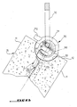
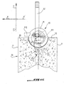
- the anchor is adapted to lifting, lifting and turning panels in one hardenable material, including but not limited to prefabricated concrete panels 10.
- Such a panel typically has a shape general of parallelepiped rectangle, weak thickness in a first direction X-X ' relative to its dimensions in a plane perpendicular to this first direction.
- This panel 10 is delimited by two large faces 11 opposite perpendicular to the first direction X-X ', and four small faces 12 connecting the two big faces 11, constituting the edge of the panel 10.
- Two opposite small faces 12 are perpendicular to a second direction Y-Y ', and two other small faces 12 opposite are perpendicular to a third direction Z-Z 'perpendicular to the second.
- the second and third directions Y-Y 'and Z-Z' are perpendicular to the first one.
- the two big faces 11 are usually planes but may have various forms Geometric. If the shapes of the panels to be lifted are generally parallelepipedic, more mass of various forms may justify the use of this type of anchored.
- Anchor 2 includes an elongate shaft substantially in the second direction Y-Y ', having a main part 23 embedded in the panel 10, and an outer portion 21 secured to one end of the main part 23 and aligned therewith.
- the outer portion 21 protrudes from the panel 10.
- the anchor 2 further comprises a gripping head 30 secured to the end of the outer portion 21 opposed to the main part 23, and a boss 40 increasing the thickness of the outer part 21 of the rod 20 in the first direction.
- the rod 20 is perpendicular to the second direction Y-Y 'a strong section, of several millimeters in width following the first and third directions.
- the anchor 2 is of the spherical head type, this head being intended to cooperate, both for the lifting, lifting and turning, with a ring 70 of the type described in FR-A-1 patent documents 568,605, FR-A-2,382,398 and EP-B-0,679,143.
- the head 30 has the shape of a solid disk, with axis extending in the second direction Y-Y ', of greater diameter than the width of the stem at less in the first or third direction.
- the ring 70 comprises a spherical piece 71 of connection with the head 30 of the anchor, called nut, and a ring 72 connecting the nut 71 and the hoist, called shackle.
- the nut has an arcuate groove 711 centered on the center of the nut 71 and extending substantially over a quarter circle, open on one side radially outside, in which is engaged the head 30 of the anchor.
- the groove 711 has a T-section, and includes a radially inner zone of width relatively larger to receive the head 30 anchor 2, and a radially outer zone of relatively smaller width intended to receive the outer portion 21 of the rod 20.
- the width of the inner area of groove 711 corresponds to the diameter of the head 30, and the width of the outer zone corresponds to the width of the part outside 21, considered in the third direction ZZ '.
- the groove 711 comprises at one end an orifice for introducing the head 30 of the anchor into the groove 711, and has a side opposite the orifice introduction a blind end, the head occupying during the lifting and lifting operations of the panel a handling position in which she comes into abutment against this one-eyed end.
- the part outer 21 of the rod 20 and the head 30 of the anchor 2 are arranged in a hemispheric reservation 13 arranged in a small face 12 of the panel 10 perpendicular to the second direction Y-Y ', this reservation 13 with a diameter slightly greater than that of walnut 71.
- the lifting operation of the panel 10 is performed first by engaging the nut 71 in the reservation 13, so that the head 30 of the anchor 2 gets into the hole of the groove 711.
- the nut 71 is oriented so that the groove 711 extends into a plane containing the first and second directions, its blind end being turned towards the high, on the side towards which the effort of lift.
- the nut 71 is then rotated to bring the head 30 abuts at the blind end of the groove 71.
- the shackle 72 then extends in the first direction X-X ', or is slightly inclined relative to the first direction. We are in the situation of the Figure 1A.
- the effort exerted by the means on the lifting anchor is oriented substantially in the first direction X-X ', and is represented by the arrow F of FIG. 1A.
- the force exerted by the lifting means is oriented in the second direction Y-Y ', as shown in FIG. 1C, the shackle 72 also extending along this direction.
- the head 30 is still at the blind end of the groove 71.
- the means of lifting exert a force following the second direction Y-Y ' on the anchor 2.
- the boss 40 protrudes into the first X-X 'direction relative to the rod 20, on one side higher thereof, and has substantially the same width as the rod in the third direction Z-Z '. It extends along the second Y-Y 'direction along the head 30 and along the outer portion 21 of the stem, and forms a shoulder 25 on a side opposite to the head 30.
- the boss 40 increases the rigidity of the rod 20 in the first direction X-X ', and avoids that this rod does not deform during the lifting operation. Such deformation would have the effect that the nut 71 come to bear against the surface of the reservation 13, damaging the concrete at the point of contact.
- the boss 40 extends practically along the entire head 30 of the anchor, and protrudes into the first direction X-X 'with respect to the periphery of this head 30. It follows that when the head 30 is located at the blind end of the groove 71, the boss 40 is interposed between this end and the head 30.
- the presence of the boss 40 is particularly advantageous when the anchor 2 cooperates with a nut 71 carrying a substantially radial actuating lug 712.
- the tab 712 extends upwards along the first direction X-X ', to immediate proximity of the small face 12 of the panel 10.
- the presence of the boss 40 along the head 30 makes that the pivoting stroke of the nut 71 to make pass the head from the hole to the blind end of the groove is shorter, so that the tab 712 is further away from the small face 12 of the panel 10. The risk that the paw comes to rub against the small face 12 and damage the concrete is removed.
- the anchor 2 comprises at least two oblique anchoring wings 50 extending along the stem 20 from the boss 40 on two opposite sides of this rod 20, in a direction oblique to the first and second directions X-X 'and Y-Y', in a sense general opposite to the head 30.
- the two oblique wings 50 are thin, and extend in the same plane substantially parallel to the third direction Z-Z '.
- These oblique wings 50 are born immediately behind the recess of reservation 13, at the level of the shoulder 25 and are widening regularly following the third direction Z-Z 'to from the boss 40.
- Each has a width relatively weak in the third direction Z-Z 'at level of the shoulder 25, this width going increasing regularly when following the next wing the oblique direction away from the shoulder 25.
- Each oblique wing 50 extends from an opposite side at the boss 40 along the rod 20 by a second wing anchoring 60, these second wings 60 being mutually parallel and extending in one direction longitudinal from the oblique wings 50.
- These second wings 60 are for example widths constant following the third direction Z-Z ', but may also have a variable width.
- each second wing 60 is extended on one side opposite the oblique wings 50 along the rod 20 by a third anchor wing 65 extending along the same longitudinal direction as the second wings 60.
- These third wings 65 are narrowing regularly following the third direction Z-Z 'to from the second wings 60.
- Each presents a relatively larger width according to the third Z-Z 'direction at its end closest to the second wing 60, this width decreasing regularly when we follow the third wing following the longitudinal direction away from the second wing 60.
- this width is zero, the third wing 65 thus forming a tip on the side opposite the head 30.
- the second and third wings 60 and 65 extend almost the entire length of the main part 23 in the second direction Y-Y ', substantially to an inner end 22 of the rod 20 opposite the outer portion 21.
- each of the second wings 60 following the third direction Z-Z ' is substantially equal to that of the main part 23 of the stem 20.
- the respective maximum widths of the oblique wings 50 and third wings 65 are also substantially equal to the width of the main part 23 of the stem 20.
- the wings obliques 50 considered in section perpendicular to the oblique direction, have sections trapezoidal, touching the rod 20 by their large bases.
- the second wings 60 and the third wings 65 considered in section perpendicular to the longitudinal direction, have sections trapezoidal, touching the rod 20 by their large bases.
- the oblique wings 50, the second wings 60 and the third wings 65 therefore have a thickness decreasing from rod 20 to a free edge outside opposite the rod 20.
- the wings may have triangular sections, decreasing in thickness from of the stem 20.
- thickness of the second or third wings the dimension of it considered following a direction perpendicular to both the direction longitudinal and in the third direction Z-Z '.
- oblique wing thickness the dimension of this considered in a perpendicular direction both at the oblique direction and at the third direction Z-Z '.
- the free edge of the oblique wing 50 deviates from the rod 20 from the shoulder 25, and extends oblique to one end of the free edge of the second wing 60. Similarly, the free edge of the oblique wing 50 away from the rod 20, and extends obliquely to a other end of the free edge of the second wing 60.
- Figure 3 shows that the main part 23 of the rod 20, considered in section perpendicular to the second direction Y-Y ', presents a section rectangular elongated in the first direction X-X '.
- the size ratio between large and small sides of this rectangular section is of the order of two.
- the main part 23 of the rod 20 is thus bounded by two long sides 24 planes, mutually parallel and opposite, perpendicular to the third direction Z-Z '.
- the oblique wings 50, the second wings 60 and the third wings 65 stretch along these great sides 24.
- the thickness of the wings at the rod 20 is about a third of the height of the large faces 24 considered in the first direction X-X '.
- the thickness of the wings at their free edges respective is small relative to the height of large faces 24.
- the second wings 60 and the third wings 65 are each delimited by converging upper faces 80 and lower 81, constituting the two opposite non-parallel sides of the trapezoidal section.
- These upper and lower faces 80/81 form each an angle slightly greater than 90 ° to at the big side 24 carrying the corresponding wing.
- the angle formed by the upper face 80 is slightly larger that the angle formed by the lower face 81.
- a top part of this section corresponding to the boss 40, has a half-disk shape.
- the end portion 21 is also bounded by two long flat sides, mutually parallel and opposite, perpendicular to the third direction Z-Z ', as an extension of the long sides 24 of the main part 23 of the rod 20.
- main part 23 protrudes on the lower side with respect to the end portion 21, a rounded shoulder making the transition between two parts.
- the anchor 2 still includes an eye 90 made to the inner end 22 of the main part 23, this eye 90 having a cylindrical shape of axis parallel to the third direction Z-Z 'and being intended to receive a preformed steel pin-shaped called hanger, no represent.
- the base of the eye 90 that is to say the part of the eye 90 farthest from the end portion 21 in following the second direction Y-Y ', preferably two opposite ends flared, so that the hairpin is, as soon as it is put in place the eye, in contact with the inner surface of this eye.
- the end inner 22 provided with an eye 90 can be replaced by a conical foot with an axis parallel to the second direction Y-Y ', converging towards the head 30, so as to create a compression zone towards this head.
- the anchor comprises a cylindrical hole 91 axis parallel to the third direction Z-2 ', intended for receive a straight cylindrical bar of short length.
- the diameter and length of the bar and the are determined by calculation, according to the dimensions of the panel and its mass.
- the anchor is self-sufficient in a controlled use, ie for handling mass panels and dimensions in accordance with usage requirements associated with each model Anchor.
- the use of the suspension and / or bar increases the coefficient of safety of the anchor.
- the second wings 60 and the third wings 65 all extend in the same plane substantially parallel to the second direction Y-Y '.
- This plan is located substantially halfway up the part 23 of the rod 20, the height being considered following the first direction X-X '.
- the second wings 60 are thus arranged in a plane passing through the axis of the stem 20.
- the second wing 60 presents in its direction longitudinal a length substantially equal to twice the length of the oblique wing 50 in the direction oblique.
- the third wing 65 presents in its direction longitudinal a length less than the length of the oblique wing 50 in the oblique direction.
- This oblique direction forms an angle of 30 ° approximately with the first direction X-X 'and about 60 ° with the second direction Y-Y '.
- the ring 70 exerts on the anchor a force in the first direction X-X ', on the boss 40, as shown by the arrow F in FIG.
- the upper faces 80 of the three wings 50/60/65 contribute to generate by reaction in concrete, when the application of the lifting effort, a zone of compression eliminating the risks of punching. This area develops in a flared shape from wings to the surface of the panel, and gives the anchor its ability to pull back. This resistance is proportional to the volume of concrete encompassed in the zone.
- This area is particularly wide here, first because of the orientation of the upper faces 80, which at an angle of more than 90 ° to the larger sides 24, and then because of the cumulative length of three wings, which extend practically along the main part 23 of the rod 20.
- the lower face 81 of the wing oblique 50 helps to create a compression zone.
- the hole 91 is disposed at the bottom of the main part 23, under the second wing 60, at the end of this wing secured to the wing oblique 50.
- the second wings 60 and the third wings 65 all extend in the same plane substantially parallel to the second direction Y-Y '.
- This plan is located substantially down the big side 24 of the main part 23 of the rod 20, that is to say the opposite side to the boss 40.
- the second wing 60 presents in its direction longitudinal a length substantially equal to the length of the oblique wing 50 following the direction oblique.
- the third wing 65 presents in its direction longitudinal a length less than the length of the oblique wing 50 in the oblique direction.
- This oblique direction forms an angle of 30 ° approximately with the first direction X-X 'and about 60 ° with the second direction Y-Y '.
- the compression zone formed during the lifting is larger than in the first embodiment, because the second wing is shifted down.
- the shift down is not limited to the position of the lower face of the main part 23 of the rod 20. In extreme situations, it is possible to extend part 23 to allow to position the wings 60 and 65 very much below the longitudinal axis of the anchor 20 following the second direction Y-Y '. This could be justify for lifting operations excluding the turnaround.
- the hole 91 is disposed at mid-height of the main part 23, above the second wing 60, at the end of this wing secured to the oblique wing 50.
- the second and third wings can also be arranged on the large faces 24 at an intermediate height between the positions of first and second embodiments.
- the position exact is determined by calculation, according to the geometry of the panel 10. As a general rule, the higher the panel 10 is thin in the first direction X-X ', the more the wings are shifted down the big face 24 in the first direction X-X ', to create a larger compression area in lift.
- the second wings 60 and the third wings 65 all extend in the same plan that oblique wings 50.
- the direction oblique in this case forms an angle of approximately 70 ° with the first direction X-X 'and about 20 ° with the second Y-Y 'direction.
- the second wing 60 presents in the direction oblique a length equal to at least three times the length of the oblique wing 50 in the same direction oblique.
- the third wing 65 presents in the direction oblique a length substantially equal to the length of the oblique wing 50 in the same oblique direction.
- the oblique wings 50 in this mode of realization arise at the base of the shoulder 25, that is, at the point where the shoulder 25 joins the main part 23 of the rod 20.
- the three aligned wings cross each large side 24 of the main part 23 following a diagonal median, which divides it into two equal parts.
- the third wing 65 extends almost to the bottom of the big side 24, under the eye 90.
- the compression zone created by this anchor lifting is slightly inclined compared to the first direction X-X '.
- the lower faces 81 of the three wings contribute to create the compression zone, this zone being more extensive than in the first two embodiments.
- the compression zone is substantially the same as lifting, because the wings form medial diagonals of the long sides 24.
- the hole 91 is disposed at the bottom of the main part 23, under the oblique wing 50.
- anchor 2 is symmetrical by relative to a median plane containing the first and second directions X-X 'and Y-Y'.
- the outer part 21 of the stem is not symmetrical with respect to this plane. She wears on one side the boss 40 which protrudes from the part 23 of the rod in the first direction X-X ', and a side opposite the boss 40 it has a recessed portion with respect to the main portion 23 of the rod in the first direction X-X '.
- This deportation matter in the first direction X-X 'at the level of the outer part 21 makes it easier to manufacture of the anchor 2, and also optimize the use of the material, so to realize savings.
- the asymmetrical nature of the anchor results from the taking into account the distribution of constraints in the anchor during lifting, lifting and flipping, as well as optimization of the use of the material.
- oblique wings 50 connect to the boss 40 at the junction point between the main part 23 and the outer part 21 of the rod 20 makes it possible to reinforce the mechanical strength of the stem in this junction area.
- the anchor described above has multiple advantages.
- the anchor is particularly suitable for concrete, but may be used for panels made of other hardenable materials, such as cement, plaster, plastics, resin.
- the anchor is made one piece, made of metal, preferably steel, typically by a method such as forging.
- the first 50 wings are particularly long.
- the position of the second and third wings on the large faces of the stem and the inclination of oblique wings can be modified to vary the performance of the anchor in lifting, lifting flipping, depending on the specific use planned.
- the outer part of the anchor can present on one side opposite the boss 40 a second boss similar to the boss 40, replacing the portion hollow.
Landscapes
- Engineering & Computer Science (AREA)
- Architecture (AREA)
- Mechanical Engineering (AREA)
- Civil Engineering (AREA)
- Structural Engineering (AREA)
- Joining Of Building Structures In Genera (AREA)
- Conveying And Assembling Of Building Elements In Situ (AREA)
- Load-Engaging Elements For Cranes (AREA)
Priority Applications (5)
| Application Number | Priority Date | Filing Date | Title |
|---|---|---|---|
| AT04291029T ATE521767T1 (de) | 2004-04-19 | 2004-04-19 | Anker zum kippen und heben eines paneels aus härtbarem material, insbesondere beton |
| ES04291029T ES2371642T3 (es) | 2004-04-19 | 2004-04-19 | Tirante para bascular y levantar un panel de material endurecible, en particular hormigón. |
| EP04291029A EP1589163B1 (de) | 2004-04-19 | 2004-04-19 | Anker zum Kippen und Heben eines Paneels aus härtbarem Material, insbesondere Beton |
| PCT/FR2005/000786 WO2005111342A1 (fr) | 2004-04-19 | 2005-03-31 | Ancre de levage et de relevage pour panneau en materiau durcissable, notamment en beton |
| CNB2005800192829A CN100478533C (zh) | 2004-04-19 | 2005-03-31 | 可凝固材料制成的面板的提起与抬高锚固件 |
Applications Claiming Priority (1)
| Application Number | Priority Date | Filing Date | Title |
|---|---|---|---|
| EP04291029A EP1589163B1 (de) | 2004-04-19 | 2004-04-19 | Anker zum Kippen und Heben eines Paneels aus härtbarem Material, insbesondere Beton |
Publications (2)
| Publication Number | Publication Date |
|---|---|
| EP1589163A1 true EP1589163A1 (de) | 2005-10-26 |
| EP1589163B1 EP1589163B1 (de) | 2011-08-24 |
Family
ID=34931040
Family Applications (1)
| Application Number | Title | Priority Date | Filing Date |
|---|---|---|---|
| EP04291029A Expired - Lifetime EP1589163B1 (de) | 2004-04-19 | 2004-04-19 | Anker zum Kippen und Heben eines Paneels aus härtbarem Material, insbesondere Beton |
Country Status (5)
| Country | Link |
|---|---|
| EP (1) | EP1589163B1 (de) |
| CN (1) | CN100478533C (de) |
| AT (1) | ATE521767T1 (de) |
| ES (1) | ES2371642T3 (de) |
| WO (1) | WO2005111342A1 (de) |
Families Citing this family (1)
| Publication number | Priority date | Publication date | Assignee | Title |
|---|---|---|---|---|
| BRPI0622165A2 (pt) * | 2006-12-22 | 2011-12-27 | Marcel Arteon | Âncora para manusear elementos da construÇço, em particular um painel de concreto |
Citations (5)
| Publication number | Priority date | Publication date | Assignee | Title |
|---|---|---|---|---|
| US4702045A (en) * | 1985-07-27 | 1987-10-27 | Siegfried Fricker | Anchor for concreting into heavy loads |
| DE4310022A1 (de) * | 1992-03-31 | 1993-10-07 | Pfeifer Seil Hebetech | Anker für Betonfertigteile und Verfahren zu dessen Herstellung |
| US5596846A (en) * | 1995-10-13 | 1997-01-28 | The Burke Group | Lifting anchor for embedment in concrete members |
| US5857296A (en) * | 1996-05-16 | 1999-01-12 | Dayton Superior Corporation | Concrete sandwich panel erection anchor |
| US20030019169A1 (en) * | 2001-07-26 | 2003-01-30 | Dayton Superior Corporation | Concrete anchor |
Family Cites Families (1)
| Publication number | Priority date | Publication date | Assignee | Title |
|---|---|---|---|---|
| FI89473C (fi) * | 1992-04-06 | 1993-10-11 | Paroc Oy Ab | Lyftanordning och -foerfarande |
-
2004
- 2004-04-19 EP EP04291029A patent/EP1589163B1/de not_active Expired - Lifetime
- 2004-04-19 AT AT04291029T patent/ATE521767T1/de active
- 2004-04-19 ES ES04291029T patent/ES2371642T3/es not_active Expired - Lifetime
-
2005
- 2005-03-31 CN CNB2005800192829A patent/CN100478533C/zh not_active Expired - Fee Related
- 2005-03-31 WO PCT/FR2005/000786 patent/WO2005111342A1/fr not_active Ceased
Patent Citations (5)
| Publication number | Priority date | Publication date | Assignee | Title |
|---|---|---|---|---|
| US4702045A (en) * | 1985-07-27 | 1987-10-27 | Siegfried Fricker | Anchor for concreting into heavy loads |
| DE4310022A1 (de) * | 1992-03-31 | 1993-10-07 | Pfeifer Seil Hebetech | Anker für Betonfertigteile und Verfahren zu dessen Herstellung |
| US5596846A (en) * | 1995-10-13 | 1997-01-28 | The Burke Group | Lifting anchor for embedment in concrete members |
| US5857296A (en) * | 1996-05-16 | 1999-01-12 | Dayton Superior Corporation | Concrete sandwich panel erection anchor |
| US20030019169A1 (en) * | 2001-07-26 | 2003-01-30 | Dayton Superior Corporation | Concrete anchor |
Also Published As
| Publication number | Publication date |
|---|---|
| ATE521767T1 (de) | 2011-09-15 |
| CN1969103A (zh) | 2007-05-23 |
| WO2005111342A1 (fr) | 2005-11-24 |
| EP1589163B1 (de) | 2011-08-24 |
| CN100478533C (zh) | 2009-04-15 |
| ES2371642T3 (es) | 2012-01-05 |
Similar Documents
| Publication | Publication Date | Title |
|---|---|---|
| CA1335475C (fr) | Piece d'ancrage, notamment pour beton | |
| CA2714270C (fr) | Ancre de manutention d'elements de construction aux branches divergentes maintenues | |
| EP0434819B1 (de) | Hebe- und aufrichtanker, insbesondere für betonplatten | |
| EP2097597B1 (de) | Anker zur handhabung von bauelementen, insbesondere von betonplatten | |
| EP0032101A2 (de) | Vorrichtung zum Anzeigen von Materialermüdung | |
| EP1589163B1 (de) | Anker zum Kippen und Heben eines Paneels aus härtbarem Material, insbesondere Beton | |
| FR2956359A1 (fr) | Bras oscillant transversal muni d'un tourillon, pour le montage sur un essieu de vehicule automobile, et procede de fabrication dudit bras | |
| EP0289490B1 (de) | Karabinerhaken für bergsteiger, höhlenforscher und ähnliche personen | |
| FR3068962B1 (fr) | Ancre dynamique et evolutive de levage d’un element de construction, notamment de faible epaisseur, multiconfigurations et multi forces | |
| FR2794100A1 (fr) | Dispositif d'accrochage de voile | |
| EP3334874A1 (de) | Verstärkter, dynamischer hubanker für ein bauteil | |
| EP2072706B1 (de) | Decke bestehend aus Balken und Deckeneinschüben sowie aus einer nahtlos gegossenen Deckenplatte auf diesen Balken und Deckeneinschüben | |
| EP3044378B1 (de) | Fixiersystem für geotechnische anker und bewehrungsanordnung mit solchem fixiersystem | |
| FR2749603A1 (fr) | Ancre de levage et de manutention | |
| EP1477613A1 (de) | Bodenanker mit Zuggliedschutz und konkavem Eindringungsprofil | |
| FR2978467A1 (fr) | Panneau de mur comprenant une peau de beton interieure et une peau de beton exterieure | |
| CH696824A5 (fr) | Ancre d'échappement. | |
| WO2011095612A1 (fr) | Lunette de wc et procede pour sa production | |
| EP3507431A1 (de) | Verstärkter dynamischer hubanker zum anheben und umdrehen eines bauteils | |
| BE544818A (de) | ||
| FR3045587A1 (fr) | Anneau de levage a verrouillage tangentiel | |
| BE485530A (de) | ||
| BE495806A (de) | ||
| BE555387A (de) | ||
| BE514490A (de) |
Legal Events
| Date | Code | Title | Description |
|---|---|---|---|
| PUAI | Public reference made under article 153(3) epc to a published international application that has entered the european phase |
Free format text: ORIGINAL CODE: 0009012 |
|
| AK | Designated contracting states |
Kind code of ref document: A1 Designated state(s): AT BE BG CH CY CZ DE DK EE ES FI FR GB GR HU IE IT LI LU MC NL PL PT RO SE SI SK TR |
|
| AX | Request for extension of the european patent |
Extension state: AL HR LT LV MK |
|
| 17P | Request for examination filed |
Effective date: 20060314 |
|
| AKX | Designation fees paid |
Designated state(s): AT BE BG CH CY CZ DE DK EE ES FI FR GB GR HU IE IT LI LU MC NL PL PT RO SE SI SK TR |
|
| 17Q | First examination report despatched |
Effective date: 20080425 |
|
| GRAP | Despatch of communication of intention to grant a patent |
Free format text: ORIGINAL CODE: EPIDOSNIGR1 |
|
| GRAS | Grant fee paid |
Free format text: ORIGINAL CODE: EPIDOSNIGR3 |
|
| GRAA | (expected) grant |
Free format text: ORIGINAL CODE: 0009210 |
|
| AK | Designated contracting states |
Kind code of ref document: B1 Designated state(s): AT BE BG CH CY CZ DE DK EE ES FI FR GB GR HU IE IT LI LU MC NL PL PT RO SE SI SK TR |
|
| REG | Reference to a national code |
Ref country code: GB Ref legal event code: FG4D Free format text: NOT ENGLISH |
|
| REG | Reference to a national code |
Ref country code: CH Ref legal event code: EP |
|
| REG | Reference to a national code |
Ref country code: IE Ref legal event code: FG4D Free format text: LANGUAGE OF EP DOCUMENT: FRENCH |
|
| REG | Reference to a national code |
Ref country code: DE Ref legal event code: R096 Ref document number: 602004034081 Country of ref document: DE Effective date: 20111027 |
|
| REG | Reference to a national code |
Ref country code: CH Ref legal event code: NV Representative=s name: TROESCH SCHEIDEGGER WERNER AG |
|
| REG | Reference to a national code |
Ref country code: NL Ref legal event code: T3 |
|
| REG | Reference to a national code |
Ref country code: ES Ref legal event code: FG2A Ref document number: 2371642 Country of ref document: ES Kind code of ref document: T3 Effective date: 20120105 |
|
| PG25 | Lapsed in a contracting state [announced via postgrant information from national office to epo] |
Ref country code: SE Free format text: LAPSE BECAUSE OF FAILURE TO SUBMIT A TRANSLATION OF THE DESCRIPTION OR TO PAY THE FEE WITHIN THE PRESCRIBED TIME-LIMIT Effective date: 20110824 Ref country code: FI Free format text: LAPSE BECAUSE OF FAILURE TO SUBMIT A TRANSLATION OF THE DESCRIPTION OR TO PAY THE FEE WITHIN THE PRESCRIBED TIME-LIMIT Effective date: 20110824 Ref country code: PT Free format text: LAPSE BECAUSE OF FAILURE TO SUBMIT A TRANSLATION OF THE DESCRIPTION OR TO PAY THE FEE WITHIN THE PRESCRIBED TIME-LIMIT Effective date: 20111226 |
|
| PG25 | Lapsed in a contracting state [announced via postgrant information from national office to epo] |
Ref country code: PL Free format text: LAPSE BECAUSE OF FAILURE TO SUBMIT A TRANSLATION OF THE DESCRIPTION OR TO PAY THE FEE WITHIN THE PRESCRIBED TIME-LIMIT Effective date: 20110824 Ref country code: GR Free format text: LAPSE BECAUSE OF FAILURE TO SUBMIT A TRANSLATION OF THE DESCRIPTION OR TO PAY THE FEE WITHIN THE PRESCRIBED TIME-LIMIT Effective date: 20111125 Ref country code: CY Free format text: LAPSE BECAUSE OF FAILURE TO SUBMIT A TRANSLATION OF THE DESCRIPTION OR TO PAY THE FEE WITHIN THE PRESCRIBED TIME-LIMIT Effective date: 20110824 Ref country code: SI Free format text: LAPSE BECAUSE OF FAILURE TO SUBMIT A TRANSLATION OF THE DESCRIPTION OR TO PAY THE FEE WITHIN THE PRESCRIBED TIME-LIMIT Effective date: 20110824 |
|
| REG | Reference to a national code |
Ref country code: IE Ref legal event code: FD4D |
|
| PG25 | Lapsed in a contracting state [announced via postgrant information from national office to epo] |
Ref country code: SK Free format text: LAPSE BECAUSE OF FAILURE TO SUBMIT A TRANSLATION OF THE DESCRIPTION OR TO PAY THE FEE WITHIN THE PRESCRIBED TIME-LIMIT Effective date: 20110824 Ref country code: IE Free format text: LAPSE BECAUSE OF FAILURE TO SUBMIT A TRANSLATION OF THE DESCRIPTION OR TO PAY THE FEE WITHIN THE PRESCRIBED TIME-LIMIT Effective date: 20110824 Ref country code: CZ Free format text: LAPSE BECAUSE OF FAILURE TO SUBMIT A TRANSLATION OF THE DESCRIPTION OR TO PAY THE FEE WITHIN THE PRESCRIBED TIME-LIMIT Effective date: 20110824 |
|
| PG25 | Lapsed in a contracting state [announced via postgrant information from national office to epo] |
Ref country code: EE Free format text: LAPSE BECAUSE OF FAILURE TO SUBMIT A TRANSLATION OF THE DESCRIPTION OR TO PAY THE FEE WITHIN THE PRESCRIBED TIME-LIMIT Effective date: 20110824 Ref country code: RO Free format text: LAPSE BECAUSE OF FAILURE TO SUBMIT A TRANSLATION OF THE DESCRIPTION OR TO PAY THE FEE WITHIN THE PRESCRIBED TIME-LIMIT Effective date: 20110824 |
|
| PG25 | Lapsed in a contracting state [announced via postgrant information from national office to epo] |
Ref country code: DK Free format text: LAPSE BECAUSE OF FAILURE TO SUBMIT A TRANSLATION OF THE DESCRIPTION OR TO PAY THE FEE WITHIN THE PRESCRIBED TIME-LIMIT Effective date: 20110824 |
|
| PLBE | No opposition filed within time limit |
Free format text: ORIGINAL CODE: 0009261 |
|
| STAA | Information on the status of an ep patent application or granted ep patent |
Free format text: STATUS: NO OPPOSITION FILED WITHIN TIME LIMIT |
|
| PGFP | Annual fee paid to national office [announced via postgrant information from national office to epo] |
Ref country code: CH Payment date: 20120430 Year of fee payment: 9 Ref country code: LU Payment date: 20120529 Year of fee payment: 9 Ref country code: NL Payment date: 20120503 Year of fee payment: 9 Ref country code: MC Payment date: 20120502 Year of fee payment: 9 |
|
| 26N | No opposition filed |
Effective date: 20120525 |
|
| PGFP | Annual fee paid to national office [announced via postgrant information from national office to epo] |
Ref country code: GB Payment date: 20120427 Year of fee payment: 9 Ref country code: BE Payment date: 20120531 Year of fee payment: 9 |
|
| REG | Reference to a national code |
Ref country code: DE Ref legal event code: R097 Ref document number: 602004034081 Country of ref document: DE Effective date: 20120525 |
|
| PGFP | Annual fee paid to national office [announced via postgrant information from national office to epo] |
Ref country code: DE Payment date: 20120702 Year of fee payment: 9 |
|
| PGFP | Annual fee paid to national office [announced via postgrant information from national office to epo] |
Ref country code: AT Payment date: 20120502 Year of fee payment: 9 |
|
| PG25 | Lapsed in a contracting state [announced via postgrant information from national office to epo] |
Ref country code: BG Free format text: LAPSE BECAUSE OF FAILURE TO SUBMIT A TRANSLATION OF THE DESCRIPTION OR TO PAY THE FEE WITHIN THE PRESCRIBED TIME-LIMIT Effective date: 20111124 |
|
| BERE | Be: lapsed |
Owner name: ARTEON, MARCEL Effective date: 20130430 Owner name: VERDE, PATRICK Effective date: 20130430 |
|
| REG | Reference to a national code |
Ref country code: NL Ref legal event code: V1 Effective date: 20131101 |
|
| PG25 | Lapsed in a contracting state [announced via postgrant information from national office to epo] |
Ref country code: MC Free format text: LAPSE BECAUSE OF NON-PAYMENT OF DUE FEES Effective date: 20130430 |
|
| REG | Reference to a national code |
Ref country code: CH Ref legal event code: PL |
|
| REG | Reference to a national code |
Ref country code: AT Ref legal event code: MM01 Ref document number: 521767 Country of ref document: AT Kind code of ref document: T Effective date: 20130430 |
|
| GBPC | Gb: european patent ceased through non-payment of renewal fee |
Effective date: 20130419 |
|
| PG25 | Lapsed in a contracting state [announced via postgrant information from national office to epo] |
Ref country code: CH Free format text: LAPSE BECAUSE OF NON-PAYMENT OF DUE FEES Effective date: 20130430 Ref country code: GB Free format text: LAPSE BECAUSE OF NON-PAYMENT OF DUE FEES Effective date: 20130419 Ref country code: BE Free format text: LAPSE BECAUSE OF NON-PAYMENT OF DUE FEES Effective date: 20130430 Ref country code: DE Free format text: LAPSE BECAUSE OF NON-PAYMENT OF DUE FEES Effective date: 20131101 Ref country code: LI Free format text: LAPSE BECAUSE OF NON-PAYMENT OF DUE FEES Effective date: 20130430 Ref country code: AT Free format text: LAPSE BECAUSE OF NON-PAYMENT OF DUE FEES Effective date: 20130430 |
|
| REG | Reference to a national code |
Ref country code: DE Ref legal event code: R119 Ref document number: 602004034081 Country of ref document: DE Effective date: 20131101 |
|
| PG25 | Lapsed in a contracting state [announced via postgrant information from national office to epo] |
Ref country code: NL Free format text: LAPSE BECAUSE OF NON-PAYMENT OF DUE FEES Effective date: 20131101 |
|
| PG25 | Lapsed in a contracting state [announced via postgrant information from national office to epo] |
Ref country code: TR Free format text: LAPSE BECAUSE OF FAILURE TO SUBMIT A TRANSLATION OF THE DESCRIPTION OR TO PAY THE FEE WITHIN THE PRESCRIBED TIME-LIMIT Effective date: 20110824 |
|
| PG25 | Lapsed in a contracting state [announced via postgrant information from national office to epo] |
Ref country code: HU Free format text: LAPSE BECAUSE OF FAILURE TO SUBMIT A TRANSLATION OF THE DESCRIPTION OR TO PAY THE FEE WITHIN THE PRESCRIBED TIME-LIMIT Effective date: 20040419 |
|
| PG25 | Lapsed in a contracting state [announced via postgrant information from national office to epo] |
Ref country code: LU Free format text: LAPSE BECAUSE OF NON-PAYMENT OF DUE FEES Effective date: 20130419 |
|
| PGFP | Annual fee paid to national office [announced via postgrant information from national office to epo] |
Ref country code: ES Payment date: 20150522 Year of fee payment: 12 |
|
| PGFP | Annual fee paid to national office [announced via postgrant information from national office to epo] |
Ref country code: IT Payment date: 20150421 Year of fee payment: 12 |
|
| REG | Reference to a national code |
Ref country code: FR Ref legal event code: PLFP Year of fee payment: 13 |
|
| PG25 | Lapsed in a contracting state [announced via postgrant information from national office to epo] |
Ref country code: IT Free format text: LAPSE BECAUSE OF NON-PAYMENT OF DUE FEES Effective date: 20160419 |
|
| REG | Reference to a national code |
Ref country code: FR Ref legal event code: PLFP Year of fee payment: 14 |
|
| REG | Reference to a national code |
Ref country code: FR Ref legal event code: PLFP Year of fee payment: 15 |
|
| PG25 | Lapsed in a contracting state [announced via postgrant information from national office to epo] |
Ref country code: ES Free format text: LAPSE BECAUSE OF NON-PAYMENT OF DUE FEES Effective date: 20160420 |
|
| PGFP | Annual fee paid to national office [announced via postgrant information from national office to epo] |
Ref country code: FR Payment date: 20180424 Year of fee payment: 15 |
|
| REG | Reference to a national code |
Ref country code: ES Ref legal event code: FD2A Effective date: 20181204 |
|
| PG25 | Lapsed in a contracting state [announced via postgrant information from national office to epo] |
Ref country code: FR Free format text: LAPSE BECAUSE OF NON-PAYMENT OF DUE FEES Effective date: 20190430 |