EP1589152B1 - High water protection system - Google Patents
High water protection system Download PDFInfo
- Publication number
- EP1589152B1 EP1589152B1 EP05405312A EP05405312A EP1589152B1 EP 1589152 B1 EP1589152 B1 EP 1589152B1 EP 05405312 A EP05405312 A EP 05405312A EP 05405312 A EP05405312 A EP 05405312A EP 1589152 B1 EP1589152 B1 EP 1589152B1
- Authority
- EP
- European Patent Office
- Prior art keywords
- protective
- plate
- base plate
- protection system
- plates
- Prior art date
- Legal status (The legal status is an assumption and is not a legal conclusion. Google has not performed a legal analysis and makes no representation as to the accuracy of the status listed.)
- Not-in-force
Links
Images


Classifications
-
- E—FIXED CONSTRUCTIONS
- E02—HYDRAULIC ENGINEERING; FOUNDATIONS; SOIL SHIFTING
- E02B—HYDRAULIC ENGINEERING
- E02B3/00—Engineering works in connection with control or use of streams, rivers, coasts, or other marine sites; Sealings or joints for engineering works in general
- E02B3/04—Structures or apparatus for, or methods of, protecting banks, coasts, or harbours
- E02B3/10—Dams; Dykes; Sluice ways or other structures for dykes, dams, or the like
- E02B3/102—Permanently installed raisable dykes
Definitions
- the invention relates to a flood protection system typically with a plurality of protective elements, in which flood protection is erected by folding protective elements.
- flood protection is a well-known problem especially in densely populated areas, which are threatened by rivers, lakes or also by their proximity to the sea. But also for the protection of important civilian or even military installations and facilities a functioning flood protection is an increasingly important task. While in areas with frequent or permanent hazard potential, especially in coastal areas with storm surge danger, usually dikes with a maximum hazard potential corresponding protection height are used, was long time in areas with only occasional flood hazard potential on emergency measures, e.g. with the protection of areas with sandbags or exceptionally with dam beams, resorted to in acute danger.
- dams and dikes of appropriate height or completely off.
- the boundaries between the water from which the hazard originates and the vulnerable zones in many cases run straight in populated areas, so that obstructing such dams and dykes does not meet with the acceptance required for safety.
- the structural measures do not or only slightly disturbing, if the threat is not acute, so at normal or only slightly increased water level.
- a structural measure with hinged elements in which a receiving chamber on the one hand, a floodable swimming chamber and on the other hand, a Einschwenkhunt includes and the pivoting element is pivoted from the horizontal to the vertical.
- the structural measure described there is based on the basic idea of causing or at least supporting the swiveling out by the floating of the protective wall designed as a pontoon part in the floating chamber. However, this has not turned out to be advantageous.
- the surface of the protective elements should be used for other purposes at those times when there is no acute danger, such as footpaths, driveways, etc.
- a flood protection is known in which the floating chamber can already be dispensed with and in which by means of a drive means the protective position in the unfolded state or the rest position can be taken. In the unfolded state while a part of the flap wall is lowered into a channel substructure.
- the drive device be effective in or on the pivot bearing.
- German utility model DE-202 04 097 U1 is one of the WO 99/24675 A1 advanced flood protection with hinged elements known, which also has a channel for lowering a portion of the folding elements and for receiving the drive elements.
- the invention solves the problem by a flood protection according to claim 1 and a method according to claim 16.
- the measures of the invention initially have the consequence that the base plates are sealed against each other and that a relatively simple and inexpensive construction can be implemented standardized, without that the protection requirements against the flood threat would have to be compromised.
- Another consequence of the measures of the invention is that it is possible to dispense with a separate, at most, vulnerable drive system for erecting the protective elements, without necessitating a high level of manual effort.
- Contribute to the measures of the invention in their combination Due to the special nature of the interaction of the elements is taken into account in particular that a freezing of the elements by penetrating rainwater etc. prevents safe opening. With a corresponding design of the thickness of the elements safe driving is also possible without damaging the elements in the folded state, since - in contrast to the in the DE-A-102 40 687 proposed solution - a touching flap surface can be ensured.
- the flood protection system comprises a plurality of protective elements, each at least a first, pivotable protective plate for forming a protective wall in a tilted state in an inclined position and to form a substantially flat surface in a horizontal, Schutz Signswin state, a second, approximately horizontally on the ground fixed base plate, at least two support means - preferably heavy duty ceiling supports with top plates -
- sealing means for sealing the protective plate against the base plate and for sealing two juxtaposed protective plates against each other, namely sealing tapes that can be used without friction surface. The sealing means then act sealing when the protective plates are in the swung-open protective state.
- the base plates are chamfered down to the side of the adjacent base plate, respectively, because they can be reliably relocated with minimum clearance through the use of tools (e.g., lift trucks).
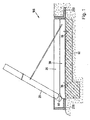
- the designated in Figure 1 as a whole with 100 flood protection system consists of a bottom element as applied to an L-shaped reinforced concrete foundation 60 base plate 30 and to the base plate 30 made of reinforced concrete with a hinge 40 pivotally mounted protective plate 20 - also made of reinforced concrete.
- a final foundation 210 is to see, usually a road or building completion.
- the end foundation 220 forms a channel towards the side of the plate to allow a smooth pivoting of the protective plate 20.
- each base plate 30 has four anchoring holes - to see, with which the base plate 30 on - in the present embodiment, L-shaped - reinforced concrete foundation 60 is fixed by means of composite anchors.
- FIG. 2 shows the protective plates 20 used in the present exemplary embodiment.
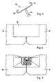
- FIG 3 the side by side arranged base plates 30 are shown, which are sealed with each other with a Vergussbetonmasse 72.
- the grouting concrete mass 72 has an E-modulus which is selected such that the concreting takes place without shrinkage cracks occurring.
- the Vergussbetonmasse is thereby filled in an area which are formed by recesses respectively at the edges of the base plates 30 and in which are Renarmtechniksbügel, which overlap each other after the finished assembly of the elements.
- so-called distribution iron are used before the concreting is carried out with the special grouting concrete with sealing additive.
- Figure 4 shows the hinge means 40 for the pivotal movement of the protective plate 20 against the base plate 30. It has been found that for a plate with a length of 6 m (relative to the bottom plate 30) two chrome steel hinges with a length of 150 mm and a thickness of 20 mm suffice.
- - particularly advantageous - anchoring plates 42 and 43 with a thickness of 20 mm and a depth of typically 70 to 120 mm - in the embodiment of 90 mm - in the protective plate 20 and in the base plate 30 at an angle of about 45 ° incorporated.
- the two plates 20 and 30 are chamfered at an angle of approximately 30 ° and a depth of approximately 370 mm in order to allow an opening region for the opening of the hinge and thus the swiveling up of the protective plate 20 ,
- this chamfered region in the described embodiment, approximately in the middle, sealing strips 70 are arranged both on the base plate 30 and on the protective plate 20 over the entire length of the plates. This relationship is also apparent from Fig. 10.
- FIG. 5 shows the configuration of the support supports 52.
- the support supports 52 have laterally a holder 58 into which the top plates 56 of the heavy-duty ceiling supports 50 are inserted.
- heavy-duty ceiling supports according to DIN 4424 are provided in order to use a standard part if necessary.
- the support supports 52 are anchored in the protective plates 20 as well as in the bottom plates 30 by means of the head bolt dowels 54 and have in the present embodiment at an angle of 30 ° to 45 ° relative to the plate surface so that they can support the top plates 56 of the heavy duty ceiling supports 50 just.
- recesses for receiving the heavy duty ceiling supports 50 are provided in the resting state of the flood protection system in the bottom plates.
- the particularly advantageous protective mechanism of the flood protection system according to the invention results, in which a pivoting of the protective plate 20 is provided by about 60 °. If this angle is to be changed, it must - in addition to the length described below. Supports 50 and the mounting arrangement - to the angle of the chamfering of the two plates 20 and 30 are changed. However, it has been found that a pivoting of the protective plates 20 by 55 ° to 65 °, preferably in about 60 ° allows the best static conditions.
- the erecting of the protective plates 20 is provided according to the present invention by means of a lifting device (jib crane), which raises the individual protective plates 20 of the flood protection system successively and thus produces a protective barrier.
- a lifting device jib crane
- the protective plates 20 with the widening formed above each be raised first.
- a manual erection of the protective plates 20 is possible for the flood protection system described here, but this requires the use of some people.
- two of the heavy-load ceiling supports 50 described above per protective plate 20 are then inserted into the holder for the top plates and can at best even by a securing element (fasteners such as bolts, cotter pin or the like) are secured.
- the high-wave protective elements can be connected laterally to existing buildings, etc.
- the buildings are provided, for example, with facilities that correspond to the joint seals between the individual protective plates 20 and are equally effective. This can be effected by oblique projections as in the protective plates 20.
- the obliquely erected protective plates can be temporarily sealed to the corresponding structures after erection, e.g. by metal angles, etc.
- threaded elements are then provided in the outer protective plates 20 in order to sealably secure such angles to the protective plates.
Landscapes
- Engineering & Computer Science (AREA)
- General Engineering & Computer Science (AREA)
- Environmental & Geological Engineering (AREA)
- Ocean & Marine Engineering (AREA)
- Mechanical Engineering (AREA)
- Civil Engineering (AREA)
- Structural Engineering (AREA)
- Buildings Adapted To Withstand Abnormal External Influences (AREA)
- Revetment (AREA)
- Air Bags (AREA)
Abstract
Description
Die Erfindung betrifft ein Hochwasserschutzsystem typischerweise mit einer Vielzahl von Schutzelementen, bei dem durch hochklappbare Schutzelemente ein Hochwasserschutz errichtet wird.The invention relates to a flood protection system typically with a plurality of protective elements, in which flood protection is erected by folding protective elements.
Hochwasserschutz ist insbesondere in dichtbesiedelten Gebieten, die durch Flüsse, Seen oder auch durch ihre Meeresnähe hochwassergefährdet sind, ein bekanntes Problem. Aber auch zum Schutz wichtiger ziviler oder sogar militärischer Anlagen und Einrichtungen ist ein funktionierender Hochwasserschutz eine immer wichtiger werdende Aufgabe. Während in Gebieten mit häufigem oder ständigem Gefährdungspotential, insbesondere in Küstengebieten mit Sturmflutgefahr, üblicherweise Deiche mit einer dem maximalen Gefährdungspotential entsprechenden Schutzhöhe zum Einsatz kommen, wurde lange Zeit in Gebieten mit nur gelegentlichem Hochwassergefährdungspotential auf Notmassnahmen, z.B. mit dem Schutz von Gebieten mit Sandsäcken oder ausnahmsweise mit Dammbalken, bei akuter Gefahr zurückgegriffen.Flood protection is a well-known problem especially in densely populated areas, which are threatened by rivers, lakes or also by their proximity to the sea. But also for the protection of important civilian or even military installations and facilities a functioning flood protection is an increasingly important task. While in areas with frequent or permanent hazard potential, especially in coastal areas with storm surge danger, usually dikes with a maximum hazard potential corresponding protection height are used, was long time in areas with only occasional flood hazard potential on emergency measures, e.g. with the protection of areas with sandbags or exceptionally with dam beams, resorted to in acute danger.
Insbesondere an Flüssen und anderen Gewässern mit ähnlichem Gefährdungspotential war aber seit langem auch ein anderer Hochwasserschutz bekannt und üblich, nämlich die Flutung von speziellen Überflutungsgebieten, bei denen, z.B. als Wiesen, kein nennenswerter Schaden zu befürchten war. Durch dieses gesteuerte Fluten wurde der Hochwasserpegel an den gefährdeten Stellen massiv gesenkt und damit das akute Gefährdungspotential vermindert.In particular, on rivers and other waters with similar potential danger but also another flood protection has long been known and common, namely the flooding of special flood areas where, for example as Meadows, no significant damage was to be feared. Through this controlled flooding, the flood level was massively reduced at the vulnerable places and thus reduced the acute hazard potential.
Durch gestiegenen Zivilisationsdruck aber wurde die Ausweisung von entsprechenden Überflutungsgebieten immer schwieriger, so dass in den letzten Jahren an vielen Stellen der Welt Überschwemmungen auch von besiedeltem Gebiet mit untragbar grossen Schäden auftraten. Zudem ist auch das von den Gewässern ausgehende Gefährdungspotential dadurch angestiegen, dass insbesondere Flüsse mehr und mehr begradigt, kanalisiert oder auf andere Art eingeengt wurden, so dass ihnen ihre natürlichen Ausweichmöglichkeiten im Hochwasserfall genommen wurden.However, increased civilization pressure has made the designation of floodplain areas increasingly difficult, with the result that in many parts of the world in recent years floods have also occurred in populated areas with unacceptably high levels of damage. In addition, the risk posed by the waters has also risen as a result of the fact that rivers in particular have been straightened, channeled or otherwise narrowed, so that their natural alternatives have been taken in the event of floods.
Grundsätzlich ist es möglich, mit Dämmen und Deichen entsprechender Bauhöhe die Gefährdung von besiedeltem Gebiet zu mindern oder ganz auszuschalten. Allerdings verlaufen die Grenzen zwischen dem Gewässer, von dem die Gefährdung ausgeht und den gefährdeten Zonen in vielen Fällen gerade in besiedeltem Gebiet, so dass eine Verbauung mit solchen Dämmen und Deichen nicht auf die zur Sicherung notwendige Akzeptanz stösst. Zumeist wird zudem gewünscht oder verlangt, dass die baulichen Massnahmen nicht oder nur wenig störend wirken, wenn die Gefährdung nicht akut ist, also bei normalem oder nur gering erhöhtem Wasserstand.Basically, it is possible to reduce the risk of populated areas with dams and dikes of appropriate height or completely off. However, the boundaries between the water from which the hazard originates and the vulnerable zones in many cases run straight in populated areas, so that obstructing such dams and dykes does not meet with the acceptance required for safety. In most cases, it is also desired or required that the structural measures do not or only slightly disturbing, if the threat is not acute, so at normal or only slightly increased water level.
Seit langem ist es bekannt, mit baulichen Massnahmen Schutzzonen gegen Überschwemmungen zu schaffen, wobei die Schutzelemente ohne akute Gefährdung ganz oder teilweise abgesenkt werden können. Dabei gibt es grundsätzlich verschiedene Schutzmöglichkeiten, wie das vertikale Ausfahren von Schutzwänden oder das Hochklappen von Schutzelementen, wobei - je nach den baulichen und bedrohungsseitigen Rahmenbedingungen - einer der Möglichkeiten der Vorzug zu geben ist.For a long time, it has been known to create protection zones against floods with structural measures, whereby the protective elements can be completely or partially lowered without acute danger. There are basically various protection options, such as the vertical extension of protective walls or the folding of protective elements, depending on the constructional and threat-related conditions one of the possibilities should be preferred.
Aus der
Aus der
Aus dem deutschen Gebrauchsmuster
Bei einer Abschätzung der Durchführbarkeit von solchen permanenten Hochwasserschutzsystemen hat sich nun ergeben, dass der Aufwand - und damit die Kosten - für einen solchen Hochwasserschutz so erheblich sein kann, dass eine planmässige Verbauung insbesondere über eine grössere Schutzlänge nicht realisiert werden kann. Damit wird der Wert der vorstehend diskutierten Schutzsysteme nicht in Frage gestellt, lediglich bei längeren Verbauungslinien sind auch Alternativen permanenter Hochwasserschutzverbauung mit beweglichen, in Ruhestellung nicht störenden Schutzelementen zu suchen.In an estimation of the feasibility of such permanent flood protection systems has now shown that the cost - and thus the cost - for such a flood protection can be so significant that a planned obstruction can not be realized in particular over a longer protection length. Thus, the value of the above-discussed protection systems is not questioned, only for longer Verbauungslinien are also alternatives permanent flood protection with movable, at rest not disturbing protective elements to look for.
Weiterhin wird von dem durch die vorliegende Erfindung vorgeschlagenen Hochwasserschutzsystem verlangt werden müssen, dass eine Verbauung einfach und schnell ausgeführt werden können muss und dass das "Aufrichten" der Schutzelemente mit einfachen Mitteln durchgeführt werden kann.Furthermore, from the flood protection system proposed by the present invention, it must be required that an obstruction can be easily and quickly carried out and that the "erection" of the protective elements can be carried out by simple means.
In der
Als weiteres Problem hat sich herausgestellt, dass die eingesetzten Schutzelemente im Boden so gut verankert sein müssen, dass sie auch bei einem Anschwellen des Grundwasserpegels fest in ihrer Verankerung verbleiben. Insbesondere ist es wünschenswert, dass im eingeklappten Zustand des Hochwasserschutzsystems die Verbauungslinie strassenartig befahrbar sein soll. Bei der Verlegung sind weiterhin Massnahmen vorzusehen, die ein Einfrieren durch Regenwasser und damit ein ungestörtes Aufklappen auch in einem solchen Zustand verhindern. Wie sich herausgestellt hat, sind diese Aufgaben mit der
Die vorstehend beschriebenen Probleme mit den bestehenden, zuvor vorgeschlagenen Hochwasserschutzsystemen gilt es also durch die vorliegende Erfindung zu lösen.The above-described problems with the existing, previously proposed flood protection systems, it is therefore to be solved by the present invention.
Die Erfindung löst die Aufgabe durch einen Hochwasserschutz nach Anspruch 1 und ein Verfahren nach Anspruch 16. Dabei haben die Massnahmen der Erfindung zunächst einmal zur Folge, dass die Grundplatten gegeneinander abgedichtet sind und dass eine relativ einfache und wenig aufwendige Konstruktion standardisiert implementiert werden kann, ohne dass an den Schutzanforderungen gegenüber der Hochwasserbedrohung irgendwelche Abstriche gemacht werden müssten. Als weiteres haben die Massnahmen der Erfindung zur Folge, dass auf ein eigenes, allenfalls anfälliges Antriebssystem für das Aufrichten der Schutzelemente verzichtet werden kann, ohne dass dabei ein hoher händischer Aufwand notwendig wird. Dazu tragen die Massnahmen der Erfindung in ihrer Kombination bei. Durch die spezielle Art des Zusammenspiels der Elemente ist insbesondere berücksichtigt, dass ein Festfrieren der Elemente durch eingedrungenes Regenwasser etc. ein sicheres Öffnen verhindert. Bei einer entsprechenden Auslegung der Dicke der Elemente ist zudem ein sicheres Befahren ohne Beschädigung der Elemente im eingeklappten Zustand möglich, da - im Gegensatz zu der in der
Das Hochwasserschutzsystem umfasst eine Vielzahl von Schutzelementen, die jeweils zumindest eine erste, schwenkbare Schutzplatte zur Ausbildung einer Schutzwand in einem in eine Schrägstellung geschwenkten Zustand und zur Ausbildung einer im wesentlichen ebenen Fläche in einem horizontalen, schutzwirkungsfreien Zustand, eine zweite, in etwa waagerecht am Boden festinstallierte Grundplatte, zumindest zwei Stützmittel - vorzugsweise Schwerlastdeckenstützen mit Kopfplatten - zum Abstützen der Schutzplatten in der in Schrägstellung geschwenktem Zustand, Dichtmittel zum Abdichten der Schutzplatte gegen die Grundplatte und zum Abdichten von zwei nebeneinander angeordneten Schutzplatten gegeneinander, nämlich Dichtbänder, die ohne Reibungsfläche eingesetzt werden können. Die Dichtmittel wirken dann dichtend, wenn sich die Schutzplatten in aufgeschwenkten Schutzzustand befinden.The flood protection system comprises a plurality of protective elements, each at least a first, pivotable protective plate for forming a protective wall in a tilted state in an inclined position and to form a substantially flat surface in a horizontal, Schutzwirkungsfreien state, a second, approximately horizontally on the ground fixed base plate, at least two support means - preferably heavy duty ceiling supports with top plates - For supporting the protective plates in the swung in inclined state, sealing means for sealing the protective plate against the base plate and for sealing two juxtaposed protective plates against each other, namely sealing tapes that can be used without friction surface. The sealing means then act sealing when the protective plates are in the swung-open protective state.
Nicht unterschätzt werden sollte das Merkmal, dass die Schutzplatten überlappende Fugen aufweisen, die dann beim Wasseranstau durch den Wasserdruck verstärkend abdichten.It should not be underestimated that the protective panels have overlapping joints which then reinforce the water accumulation by the water pressure.
Weiterhin nicht unterschätzt werden sollte das Merkmal, dass die Grundplatten unten jeweils zu der Seite der benachbarten Grundplatte angefast sind, da sie so zuverlässig mit minimalem Abstand durch den Einsatz von Hilfsmitteln (z.B. Hubstaplern) verlegt werden können.Further, it should not be underestimated that the base plates are chamfered down to the side of the adjacent base plate, respectively, because they can be reliably relocated with minimum clearance through the use of tools (e.g., lift trucks).
Weitere vorteilhafte Einzelheiten der Erfindung sind in den abhängigen Ansprüchen dargelegt.Further advantageous details of the invention are set forth in the dependent claims.
Die vorgenannten sowie die beanspruchten und in den nachfolgenden Ausführungsbeispielen beschriebenen erfindungsgemäss zu verwendenden Elemente unterliegen in ihrer Größe, Formgestaltung, Materialverwendung und technischen Konzeption keinen besonderen Ausnahmebedingungen, so dass die in dem jeweiligen Anwendungsgebiet bekannten Auswahlkriterien uneingeschränkt Anwendung finden können.The above-mentioned and the claimed and described in the following embodiments described elements to be used according to the invention are not subject to any special conditions of exception in terms of their size, shape design, material usage and technical design, so that the selection criteria known in the respective field of application can be used without restriction.
Weitere Einzelheiten, Merkmale und Vorteile des Gegenstandes der Erfindung ergeben sich aus der nachfolgenden Beschreibung der dazugehörigen Zeichnungen, in denen - beispielhaft - ein Hochwasserschutzsystem zur vorliegenden Erfindung erläutert wird.Further details, features and advantages of the subject matter of the invention will become apparent from the following description of the accompanying drawings, in which - by way of example - a flood protection system for the present invention will be explained.
In den Zeichnungen zeigen:
- Figur 1
- eine Seitenansicht der Hochwasserschutzanordnung gemäss einem ersten Ausführungsbeispiel zur vorliegenden Erfindung;
- Figur 2
- eine Vorderansicht von mehreren Elementen nach Figur 1;
- Figur 3
- eine Ansicht von nebeneinander liegenden Bodenplatten der Hochwasserschutzanordnung gemäss der bevorzugten Ausführung der vorliegenden Erfindung;
- Figur 4
- eine Detailansicht einer Scharnieranordnung von der Seite zur Hochwasserschutzanordnung gemäss der bevorzugten Ausführung der vorliegenden Erfindung;
- Figur 4a
- eine Ansicht nach Figur 4 von oben;
- Figur 5
- eine Ansicht der Stützenauflager in der Grundplatte und der Schutzplatte gemäss der bevorzugten Ausführung der vorliegenden Erfindung;
- Figur 6
- eine Detailansicht der Verbindung zwischen zwei Grundplatten gemäss der vorliegenden Erfindung, von der Landseite;
- Figur 7
- eine Ansicht nach Figur 6, vor dem Einbringen der Vergussbetonmasse, mit den Bewehrungselementen;
- Figur 8
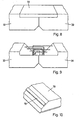
- eine Detailansicht der Verbindung zwischen zwei Grundplatten gemäss der vorliegenden Erfindung, von der Wasserseite, mit Darstellung der Anfasung im Bereich des Scharniersystems;
- Figur 9
- eine Ansicht nach Figur 8, vor dem Einbringen der Vergussbetonmasse, mit den Bewehrungselementen;
- Figur 10
- eine Ansicht des wasserseitig eingelegten Fugendichtprofils bei den Grundplatten im Anfasungsbereich.
- FIG. 1
- a side view of the flood protection arrangement according to a first embodiment of the present invention;
- FIG. 2
- a front view of several elements of Figure 1;
- FIG. 3
- a view of adjacent floor panels of the flood protection arrangement according to the preferred embodiment of the present invention;
- FIG. 4
- a detail view of a hinge assembly from the side to the flood protection arrangement according to the preferred embodiment of the present invention;
- FIG. 4a
- a view of Figure 4 from above;
- FIG. 5
- a view of the support supports in the base plate and the protective plate according to the preferred embodiment of the present invention;
- FIG. 6
- a detail view of the connection between two base plates according to the present invention, from the land side;
- FIG. 7
- a view according to Figure 6, prior to the introduction of the Vergussbetonmasse, with the reinforcing elements;
- FIG. 8
- a detail view of the connection between two base plates according to the present invention, from the water side, showing the chamfer in the region of the hinge system;
- FIG. 9
- a view of Figure 8, prior to the introduction of Vergussbetonmasse, with the reinforcing elements;
- FIG. 10
- a view of the water-side inserted joint sealing profile at the base plates in chamfering.
Das in Figur 1 als Ganzes mit 100 bezeichnete Hochwasserschutzsystem besteht aus einem Bodenelement als auf einem L-förmigen Stahlbetonfundament 60 aufgebrachte Grundplatte 30 und einen an der Grundplatte 30 aus armiertem Beton mit einer Scharnier 40 schwenkbar befestigten Schutzplatte 20 - ebenfalls aus armierten Beton. An der vorderen Seite, die im Einbau der Trockenseite entspricht, ist ein Abschlussfundament 210 zu sehen, üblicherweise ein Strassen- oder Bauwerksabschluss. An der hinteren Seite, die beim Einbau der Wasserseite entspricht, bildet das Abschlussfundament 220 zu den Plattenseiten hin einen Kanal aus, um ein problemloses Schwenken der Schutzplatte 20 zu ermöglichen.The designated in Figure 1 as a whole with 100 flood protection system consists of a bottom element as applied to an L-shaped reinforced
In der Bodenplatte 30 sind Verankerungsbohrungen 36 - im vorliegenden Ausführungsbeispiel weist jede Grundplatte 30 vier Verankerungsbohrungen auf - zu sehen, mit denen die Grundplatte 30 am - im vorliegenden Ausführungsbeispiel L-förmigen - Stahlbetonfundament 60 mit Hilfe von Verbundankern befestigt ist. In Figur 2 sind die im vorliegenden Ausführungsbeispiel verwendeten Schutzplatten 20 zu sehen.In the
In Figur 3 sind entsprechend die nebeneinander angeordneten Grundplatten 30 dargestellt, die untereinander mit einer Vergussbetonmasse 72 abgedichtet sind. Die Vergussbetonmasse 72 hat dabei ein E-Modul, das so ausgewählt ist, dass die Ausbetonierung erfolgt, ohne dass Schwindrisse auftreten. Die Vergussbetonmasse wird dabei in einen Bereich eingefüllt, die durch Aussparungen jeweils an den Rändern der Grundplatten 30 ausgebildet sind und in die hinein Anschlussarmierungsbügel stehen, die sich nach der fertigen Montage der Elemente gegenseitig überlappen. In Querrichtung der Betonelemente werden so genannte Verteilungseisen eingesetzt bevor die Ausbetonierung mit dem speziellen Vergussbeton mit Dichtungszusatz vorgenommen wird.In Figure 3, the side by side arranged
Figur 4 zeigt die Scharniereinrichtung 40 für die Schwenkbewegung der Schutzplatte 20 gegen die Grundplatte 30. Es hat sich herausgestellt, dass für eine Platte mit einer Länge von 6 m (bezogen auf die Bodenplatte 30) zwei Chromstahlscharniere mit einer Länge von 150 mm und einer Dicke von 20 mm ausreichen. Im Ausführungsbeispiel sind - besonders vorteilhaft - Verankerungsplatten 42 und 43 mit einer Dicke von 20 mm und einer Tiefe von typischerweise 70 bis 120 mm - im Ausführungsbeispiel von 90 mm - in die Schutzplatte 20 bzw. in die Grundplatte 30 in einem Winkel von ca. 45° eingearbeitet. Wie auch aus der Figur 4 hervorgeht, sind die beiden Platten 20 und 30 mit einem Winkel von ca. 30° und einer Tiefe von ca. 370 mm angefast, um einen Öffnungsbereich für das Öffnen des Scharniers und damit des Aufschwenkens der Schutzplatte 20 zu ermöglichen. In diesem angefasten Bereich, im beschriebenen Ausführungsbeispiel in etwa in der Mitte, sind sowohl an der Grundplatte 30 wie auch an der Schutzplatte 20 über die gesamte Länge der Platten Dichtbänder 70 angeordnet. Dieser Zusammenhang geht auch aus Fig. 10 hervor.Figure 4 shows the hinge means 40 for the pivotal movement of the
In Figur 5 ist die Ausgestaltung der Stützenauflager 52 dargestellt. Die Stützenauflager 52 weisen seitlich eine Halterung 58 auf, in die die Kopfplatten 56 der Schwerlastdeckenstützen 50 eingeschoben werden. Im vorliegenden Ausführungsbeispiel sind Schwerlastdeckenstützen nach DIN 4424 vorgesehen, um allenfalls ein Standardteil verwenden zu können. Die Stützenauflager 52 sind in den Schutzplatten 20 wie auch in den Bodenplatten 30 mit Hilfe der Kopfbolzendübel 54 verankert und weisen im vorliegenden Ausführungsbeispiel einen Winkel von 30° bis 45° gegenüber der Plattenoberfläche auf, damit sie die Kopfplatten 56 der Schwerlastdeckenstützen 50 eben abstützen können.FIG. 5 shows the configuration of the support supports 52. The support supports 52 have laterally a
Im vorliegenden Ausführungsbeispiel sind in den Bodenplatten 30 Aussparungen zur Aufnahme der Schwerlastdeckenstützen 50 im Ruhezustand des Hochwasserschutzsystems vorgesehen.In the
Aus den vorstehend beschriebenen geometrischen Verhältnissen ergibt sich der besonders vorteilhafte Schutzmechanismus des erfindungsgemässen Hochwasserschutzsystems, bei dem nämlich ein Aufschwenken der Schutzplatte 20 um ca. 60° vorgesehen ist. Falls dieser Winkel abgeändert werden soll, muss - neben der Länge der nachstehend beschriebenen. Stützen 50 und der Einbauanordnung - dazu der Winkel der Anfasung der beiden Platten 20 und 30 geändert werden. Allerdings hat sich herausgestellt, dass ein Aufschwenken der Schutzplatten 20 um 55° bis 65°, vorzugsweise in etwa 60° die besten statischen Verhältnisse ermöglicht.From the geometric conditions described above, the particularly advantageous protective mechanism of the flood protection system according to the invention results, in which a pivoting of the
Das Aufrichten der Schutzplatten 20 ist gemäss der vorliegenden Erfindung mit Hilfe einer Hebeeinrichtung (Schwenkkran) vorgesehen, die die einzelnen Schutzplatten 20 des Hochwasserschutzsystems nacheinander aufrichtet und somit einen Schutzwall herstellt. Im vorliegenden Ausführungsbeispiel müssen selbstverständlich die Schutzplatten 20 mit der oben ausgebildeten Verbreiterung jeweils zuerst aufgerichtet werden. Grundsätzlich ist für das hier beschriebene Hochwasserschutzsystem auch ein händisches Aufrichten der Schutzplatten 20 möglich, allerdings erfordert dies einen Einsatz von einigen Personen. Nach dem Aufrichten der Schutzplatten 20 werden sodann jeweils zwei der vorstehend beschriebenen Schwerlastdeckenstützen 50 pro Schutzplatte 20 in die Halterung für die Kopfplatten eingeschoben und können allenfalls noch durch ein Sicherungselement (Befestigungsmittel wie Schraubbolzen, Splint oder ähnliches) gesichert werden.The erecting of the
Im Weiteren wird beschrieben, wie die Hochwaaserechutzelemente seitlich an bestehende Bauten etc. angeschlossen werden können. Dabei werden die Bauten zum Beispiel mit Einrichtungen versehen, die den Fugendichtungen zwischen den einzelnen Schutzplatten 20 entsprechen bzw. gleichwirkend sind. Dies kann durch schräge Vorsprünge wie bei den Schutzplatten 20 bewirkt werden. Möglich und vorgesehen ist es aber auch, dass die schräg aufgerichteten Schutzplatten nach dem Aufrichten temporär dichtend mit den entsprechenden Bauten verbunden werden, z.B. durch Metallwinkel etc. Dazu sind dann Gewindeelemente in den äusseren Schutzplatten 20 vorgesehen, um solche Winkel an den Schutzplatten dichtend zu befestigen.In the following, it will be described how the high-wave protective elements can be connected laterally to existing buildings, etc. The buildings are provided, for example, with facilities that correspond to the joint seals between the individual
Bei einer Richtungsänderung der Verbauungslinie des Hochwasserschutzsystems gemäss dem hier beschriebenen Ausführungsbeispiel der vorliegenden Erfindung ist vorgesehen, an Stelle der Grundplatten ein der Liegehöhe der Schutzplatte entsprechendes Fundament, z.B. mit dem vorgesehenen Winkel der Richtungsänderung, bereitzustellen. Weiterhin ist für ein solches Teilstück vorgesehen, mit vorgefertigten, entsprechend der Änderung der Verbauungslinie geformten Blechplatten die entsprechende Schutzlücke zu schliessen. Solche Blechplatten werden, wie oben für die Metallwinkel beschrieben, an die aufgerichteten Schutzplatten angeschraubt.In a change in direction of the line of construction of the flood protection system according to the embodiment of the present invention described here is provided instead of the base plates of the deck height of the protective plate corresponding foundation, for example, with the intended angle of change in direction to provide. Furthermore, it is provided for such a section to close with prefabricated, according to the change in the obstruction line shaped sheet metal plates the corresponding protection gap. Such metal plates are, as above for the metal angle described screwed to the erected protective plates.
- 2020
- Schutzplatteprotection plate
- 2424
- überlappende Fugeoverlapping joint
- 2626
- Verbreiterungwidening
- 2828
- Verbreiterungwidening
- 3030
- Bodenplattebaseplate
- 3636
- Verankerungsbohrungenanchoring holes
- 4040
- Scharnierhinge
- 4242
- Verankerungsplatteanchor plate
- 4343
- Verankerungsplatteanchor plate
- 5050
- SchwerlastdeckendübelHeavy duty ceiling anchors
- 5252
- StützenauflagerStützenauflager
- 5454
- KopfbolzendübelShear studs
- 5858
- Halterungbracket
- 6060
- StahlbetonfundamentReinforced concrete foundation
- 7070
- Dichtbandsealing tape
- 7272
- Aussparung (vergossen)Recess (potted)
- 210210
- Abschlussfundamentcompletion of foundation
- 220220
- Abschlussfundamentcompletion of foundation
Claims (18)
- High-water protection system having a plurality of protective elements, wherein the protective elements comprise at least- a first, pivotable, protective plate (20), for constituting a protective wall when said plate has been pivoted into an oblique position, and for constituting a substantially flat surface when said plate is in a horizontal state without protective effect,- a second, base plate (30), which is installed on the ground in a fixed and approximately horizontal manner, the protective plate (20) and the base plate (30) being pivotally connected to a rotary or pivoting bearing means (40), and the base plate (30) having means for anchorage in the ground,- support means (50), for supporting the protective plate (20) when said plate has been pivoted into an oblique position,- a first sealing means (70), for sealing the protective plate (20) in respect of the base plate (30), the sealing means acting with sealing effect at least when the protective plate (20) has been pivoted up into the protective state,characterized in that- the base plate (30) has means by which it can be connected, respectively, to an adjacently arranged base plate,- the means comprising at least one recess at the edge of the base plate, and reinforcing elements which project into the recess,- the recess being of such dimensions that two mutually adjacent base plates can be connected to each another by grout concrete.
- High-water protection system according to claim 1, characterized in that the reinforcing elements are provided as connection reinforcement stirrups and the base plates are connected to each other by grout concrete in such a way that the reinforcement stirrups and the recesses are sealed-in.
- High-water protection system according to claim 2, characterized in that as grout concrete a material is selected such, in respect of the modulus of elasticity, that the filling with concrete can be performed without the occurrence of contraction cracks.
- High-water protection system according to any one of the preceding claims, characterized in that each base plate is bevelled at the bottom, on the side facing the adjacent base plate.
- High-water protection system according to any one of the preceding claims, characterized in that the base plate and the protective plate, each in the region of their connection line, are bevelled approximately about the designated pivot angle.
- High-water protection system according to any one of the preceding claims, characterized by a second sealing means (70), for sealing two mutually adjacent protective plates (20) in respect of each other, the second sealing means acting with sealing effect when the protective plates (20) have been pivoted up into the protective state.
- High-water protection system according to any one of the preceding claims, characterized in that the sealing means comprise sealing strips (70).
- High-water protection system according to any one of the preceding claims, characterized in that the protective plates (20) have overlapping joints (24).
- High-water protection system according to claim 8, characterized in that the second sealing means realized as sealing strips (70) is realized in an overlapping joint (24) between, respectively, two protective plates (20).
- High-water protection system according to claim 8 or 9, characterized by protective plates (20) of differing types, one type of protective plate (20) having, on both sides, an extension (26) which projects at the bottom when in the horizontal state, and the other type of protective plate (20) having, on both sides, an extension (28) which projects at the top when in the horizontal state, and the extensions (26, 28) having a thickness which is approximately half that of the protective plates (20).
- High-water protection system according to any one of the preceding claims, characterized in that the support means (50) are each realized as heavy-duty props with top plates (56).
- High-water protection system according to claim 11, characterized in that the protective plate (20) and the base plate (30) each have support bearings (52) with top bolts (54) and a holder (58) for the top plates (56) of the supports (50).
- High-water protection system according to any one of the preceding claims, characterized in that the base plate (30) has a water drainage channel (32).
- High-water protection system according to any one of the preceding claims, characterized in that each base plate (30) is fastened to a foundation by means of composite anchors, the foundation preferably being realized as an L-shaped reinforced-concrete foundation (60).
- High-water protection system according to any one of the preceding claims, characterized by a plurality of adjusting devices on the base plates (30), for adjusting the plates on the foundation (60).
- Method for moving protective elements of a high-water protection system, wherein the protective elements comprise at least- a first, pivotable, protective plate (20), for constituting a protective wall when said plate has been pivoted into an oblique position, and for constituting a substantially flat surface when said plate is in a horizontal state without protective effect,- a second, base plate (30), which is installed on the ground in a fixed and approximately horizontal manner, the protective plate (20) and the base plate (30) being pivotally connected to a rotary or pivoting bearing means (40), and the base plate (30) having means for anchorage in the ground,- support means (50), for supporting the protective plate (20) when said plate has been pivoted into an oblique position,- a first sealing means (70), for sealing the protective plate (20) in respect of the base plate (30), the sealing means acting with sealing effect at least when the protective plate (20) has been pivoted up into the protective state,characterized in that- the base plate (30) is connected, respectively, to an adjacently arranged base plate,- a recess at the edge of the base plate and reinforcing elements which project into the recess are connected to each other by grout concrete.
- Method according to claim 16, characterized in that connection reinforcement stirrups are used as reinforcing elements and the base plates are connected to each other by grout concrete, the reinforcement stirrups and the recesses being sealed-in.
- Method according to claim 17, characterized in that as grout concrete a material is used whose modulus of elasticity permits the filling with concrete without the occurrence of contraction cracks.
Applications Claiming Priority (2)
| Application Number | Priority Date | Filing Date | Title |
|---|---|---|---|
| CH6972004 | 2004-04-22 | ||
| CH6972004 | 2004-04-22 |
Publications (3)
| Publication Number | Publication Date |
|---|---|
| EP1589152A2 EP1589152A2 (en) | 2005-10-26 |
| EP1589152A3 EP1589152A3 (en) | 2007-03-07 |
| EP1589152B1 true EP1589152B1 (en) | 2007-12-12 |
Family
ID=34942974
Family Applications (1)
| Application Number | Title | Priority Date | Filing Date |
|---|---|---|---|
| EP05405312A Not-in-force EP1589152B1 (en) | 2004-04-22 | 2005-04-22 | High water protection system |
Country Status (3)
| Country | Link |
|---|---|
| EP (1) | EP1589152B1 (en) |
| AT (1) | ATE380904T1 (en) |
| DE (1) | DE502005002185D1 (en) |
Families Citing this family (4)
| Publication number | Priority date | Publication date | Assignee | Title |
|---|---|---|---|---|
| CN107338761B (en) * | 2016-11-24 | 2019-04-26 | 国家电网公司 | Concealed flood control system |
| DE102017130818B3 (en) * | 2017-12-20 | 2018-11-15 | Tu Kaiserslautern | Water barrier with a trough-shaped founding body |
| GB2598447B (en) * | 2020-11-20 | 2022-11-02 | Flood Control International Ltd | Improvements relating to flood defence |
| CN115419020B (en) * | 2022-10-11 | 2023-08-04 | 矿冶科技集团有限公司 | Emergency plugging device, flood drainage system and plugging method |
Family Cites Families (6)
| Publication number | Priority date | Publication date | Assignee | Title |
|---|---|---|---|---|
| DE48642C (en) * | A. HARTMANN SOHN in Frankfurt a. M., Neue Kräme 18 | Foldable iron protective wall against flooding for bank roads | ||
| FR2295174A1 (en) * | 1974-12-20 | 1976-07-16 | Nomballais Jean | Basculing bucket relief mechanism for barrage gate - reciprocates via ducted head water and gravity to effect incremental gate opening |
| DE7831215U1 (en) * | 1978-10-20 | 1979-03-15 | 8411 Lappersdorf | TRANSPORTABLE FLOOD SIGN FOR RAISING FLOOD PROTECTION WALLS, DYES AND OTHER WATERWATER STRENGTHS |
| DE19531922C2 (en) * | 1995-08-30 | 1999-06-17 | Erich Joseph Dipl Ing Bott | Sheet pile wall to protect against flooding |
| DE10240687A1 (en) * | 2002-09-04 | 2004-04-15 | Juri Riedel | Flood barrier, to protect property from flooding, has an angled and a horizontal shield, linked together with adjustable angles, to divide the water flows for diversion to a collection zone |
| DE20313425U1 (en) * | 2003-08-29 | 2003-11-13 | WIHAG Nutzfahrzeugfabrik GmbH & Co. KG, 33647 Bielefeld | Flood barrier section comprises barrier panel supported by support panels and hollow covering panels being fitted on these which have water-impermeable coatings on their outer sides |
-
2005
- 2005-04-22 AT AT05405312T patent/ATE380904T1/en active
- 2005-04-22 DE DE502005002185T patent/DE502005002185D1/en active Active
- 2005-04-22 EP EP05405312A patent/EP1589152B1/en not_active Not-in-force
Also Published As
| Publication number | Publication date |
|---|---|
| DE502005002185D1 (en) | 2008-01-24 |
| EP1589152A2 (en) | 2005-10-26 |
| EP1589152A3 (en) | 2007-03-07 |
| ATE380904T1 (en) | 2007-12-15 |
Similar Documents
| Publication | Publication Date | Title |
|---|---|---|
| EP0741205B1 (en) | High water protection system having one or more lowerable wall elements | |
| DE29620193U1 (en) | Mobile device for protection against flooding | |
| DE2844748C2 (en) | Drainage channel | |
| EP2921599B1 (en) | Element for the construction of a channel and method for laying elements | |
| EP1589152B1 (en) | High water protection system | |
| EP2090698A1 (en) | Water blockage, flood protection wall | |
| EP1029130A1 (en) | Protective elements, devices comprising said elements and method for protecting a zone against floods and avalanches | |
| DE202008014492U1 (en) | Sealing of channels | |
| EP0802285A2 (en) | High water protection system | |
| DE19539611C2 (en) | Flood retention barrier | |
| EP1728928A2 (en) | Mobile barrier for high water protection | |
| DE202018102880U1 (en) | Bulkhead for flood control and passage with such a bulkhead | |
| DE68912648T2 (en) | Construction method. | |
| DE102005048304A1 (en) | High water level protection unit has steel support built into ground and protective wall bands of aluminum that can be drawn out and fixed in position and lowered when the waters recede | |
| EP1707685A2 (en) | Foundation for a high water barrier | |
| DE2321647A1 (en) | PROCESS AND FINISHED PART FOR THE PRODUCTION OF A CORE OR SURFACE SEAL | |
| DE102004015322B4 (en) | Flood barrier | |
| DE20308083U1 (en) | Flood protection system | |
| DE102004025456A1 (en) | Detachable pond wall for flood protection, has wall sections each having pond area with short connecting line that runs along base between posts, and lever arm that provides torque for tilting wall section | |
| EP1738050B1 (en) | Protective wall in particular high water protective wall | |
| DE20102852U1 (en) | Plate system | |
| AT516886B1 (en) | Self-erecting and self-irritating flood protection device | |
| DE102006035593B4 (en) | Flood barrier by wall hat | |
| DE1970492U (en) | EMBOSSING MAT FOR SECURING EARTH STRUCTURES. | |
| DE202005003576U1 (en) | system wall |
Legal Events
| Date | Code | Title | Description |
|---|---|---|---|
| PUAI | Public reference made under article 153(3) epc to a published international application that has entered the european phase |
Free format text: ORIGINAL CODE: 0009012 |
|
| AK | Designated contracting states |
Kind code of ref document: A2 Designated state(s): AT BE BG CH CY CZ DE DK EE ES FI FR GB GR HU IE IS IT LI LT LU MC NL PL PT RO SE SI SK TR |
|
| AX | Request for extension of the european patent |
Extension state: AL BA HR LV MK YU |
|
| PUAL | Search report despatched |
Free format text: ORIGINAL CODE: 0009013 |
|
| AK | Designated contracting states |
Kind code of ref document: A3 Designated state(s): AT BE BG CH CY CZ DE DK EE ES FI FR GB GR HU IE IS IT LI LT LU MC NL PL PT RO SE SI SK TR |
|
| AX | Request for extension of the european patent |
Extension state: AL BA HR LV MK YU |
|
| 17P | Request for examination filed |
Effective date: 20070315 |
|
| GRAP | Despatch of communication of intention to grant a patent |
Free format text: ORIGINAL CODE: EPIDOSNIGR1 |
|
| GRAS | Grant fee paid |
Free format text: ORIGINAL CODE: EPIDOSNIGR3 |
|
| GRAA | (expected) grant |
Free format text: ORIGINAL CODE: 0009210 |
|
| AKX | Designation fees paid |
Designated state(s): AT BE BG CH CY CZ DE DK EE ES FI FR GB GR HU IE IS IT LI LT LU MC NL PL PT RO SE SI SK TR |
|
| AK | Designated contracting states |
Kind code of ref document: B1 Designated state(s): AT BE BG CH CY CZ DE DK EE ES FI FR GB GR HU IE IS IT LI LT LU MC NL PL PT RO SE SI SK TR |
|
| REG | Reference to a national code |
Ref country code: GB Ref legal event code: FG4D Free format text: NOT ENGLISH |
|
| REG | Reference to a national code |
Ref country code: CH Ref legal event code: EP |
|
| REG | Reference to a national code |
Ref country code: IE Ref legal event code: FG4D Free format text: LANGUAGE OF EP DOCUMENT: GERMAN |
|
| REF | Corresponds to: |
Ref document number: 502005002185 Country of ref document: DE Date of ref document: 20080124 Kind code of ref document: P |
|
| REG | Reference to a national code |
Ref country code: CH Ref legal event code: NV Representative=s name: R. A. EGLI & CO. PATENTANWAELTE |
|
| GBT | Gb: translation of ep patent filed (gb section 77(6)(a)/1977) |
Effective date: 20080312 |
|
| PG25 | Lapsed in a contracting state [announced via postgrant information from national office to epo] |
Ref country code: SE Free format text: LAPSE BECAUSE OF FAILURE TO SUBMIT A TRANSLATION OF THE DESCRIPTION OR TO PAY THE FEE WITHIN THE PRESCRIBED TIME-LIMIT Effective date: 20080312 |
|
| PG25 | Lapsed in a contracting state [announced via postgrant information from national office to epo] |
Ref country code: FI Free format text: LAPSE BECAUSE OF FAILURE TO SUBMIT A TRANSLATION OF THE DESCRIPTION OR TO PAY THE FEE WITHIN THE PRESCRIBED TIME-LIMIT Effective date: 20071212 Ref country code: LT Free format text: LAPSE BECAUSE OF FAILURE TO SUBMIT A TRANSLATION OF THE DESCRIPTION OR TO PAY THE FEE WITHIN THE PRESCRIBED TIME-LIMIT Effective date: 20071212 Ref country code: PL Free format text: LAPSE BECAUSE OF FAILURE TO SUBMIT A TRANSLATION OF THE DESCRIPTION OR TO PAY THE FEE WITHIN THE PRESCRIBED TIME-LIMIT Effective date: 20071212 Ref country code: SI Free format text: LAPSE BECAUSE OF FAILURE TO SUBMIT A TRANSLATION OF THE DESCRIPTION OR TO PAY THE FEE WITHIN THE PRESCRIBED TIME-LIMIT Effective date: 20071212 |
|
| REG | Reference to a national code |
Ref country code: FR Ref legal event code: RN |
|
| REG | Reference to a national code |
Ref country code: FR Ref legal event code: FC |
|
| PG25 | Lapsed in a contracting state [announced via postgrant information from national office to epo] |
Ref country code: IS Free format text: LAPSE BECAUSE OF FAILURE TO SUBMIT A TRANSLATION OF THE DESCRIPTION OR TO PAY THE FEE WITHIN THE PRESCRIBED TIME-LIMIT Effective date: 20080412 Ref country code: CZ Free format text: LAPSE BECAUSE OF FAILURE TO SUBMIT A TRANSLATION OF THE DESCRIPTION OR TO PAY THE FEE WITHIN THE PRESCRIBED TIME-LIMIT Effective date: 20071212 Ref country code: ES Free format text: LAPSE BECAUSE OF FAILURE TO SUBMIT A TRANSLATION OF THE DESCRIPTION OR TO PAY THE FEE WITHIN THE PRESCRIBED TIME-LIMIT Effective date: 20080323 |
|
| PG25 | Lapsed in a contracting state [announced via postgrant information from national office to epo] |
Ref country code: SK Free format text: LAPSE BECAUSE OF FAILURE TO SUBMIT A TRANSLATION OF THE DESCRIPTION OR TO PAY THE FEE WITHIN THE PRESCRIBED TIME-LIMIT Effective date: 20071212 Ref country code: RO Free format text: LAPSE BECAUSE OF FAILURE TO SUBMIT A TRANSLATION OF THE DESCRIPTION OR TO PAY THE FEE WITHIN THE PRESCRIBED TIME-LIMIT Effective date: 20071212 |
|
| EN | Fr: translation not filed | ||
| PG25 | Lapsed in a contracting state [announced via postgrant information from national office to epo] |
Ref country code: PT Free format text: LAPSE BECAUSE OF FAILURE TO SUBMIT A TRANSLATION OF THE DESCRIPTION OR TO PAY THE FEE WITHIN THE PRESCRIBED TIME-LIMIT Effective date: 20080512 |
|
| REG | Reference to a national code |
Ref country code: IE Ref legal event code: FD4D |
|
| ET | Fr: translation filed | ||
| PLBE | No opposition filed within time limit |
Free format text: ORIGINAL CODE: 0009261 |
|
| STAA | Information on the status of an ep patent application or granted ep patent |
Free format text: STATUS: NO OPPOSITION FILED WITHIN TIME LIMIT |
|
| PG25 | Lapsed in a contracting state [announced via postgrant information from national office to epo] |
Ref country code: FR Free format text: LAPSE BECAUSE OF FAILURE TO SUBMIT A TRANSLATION OF THE DESCRIPTION OR TO PAY THE FEE WITHIN THE PRESCRIBED TIME-LIMIT Effective date: 20080926 Ref country code: IE Free format text: LAPSE BECAUSE OF FAILURE TO SUBMIT A TRANSLATION OF THE DESCRIPTION OR TO PAY THE FEE WITHIN THE PRESCRIBED TIME-LIMIT Effective date: 20071212 Ref country code: DK Free format text: LAPSE BECAUSE OF FAILURE TO SUBMIT A TRANSLATION OF THE DESCRIPTION OR TO PAY THE FEE WITHIN THE PRESCRIBED TIME-LIMIT Effective date: 20071212 |
|
| 26N | No opposition filed |
Effective date: 20080915 |
|
| PG25 | Lapsed in a contracting state [announced via postgrant information from national office to epo] |
Ref country code: MC Free format text: LAPSE BECAUSE OF NON-PAYMENT OF DUE FEES Effective date: 20080430 |
|
| PG25 | Lapsed in a contracting state [announced via postgrant information from national office to epo] |
Ref country code: GR Free format text: LAPSE BECAUSE OF FAILURE TO SUBMIT A TRANSLATION OF THE DESCRIPTION OR TO PAY THE FEE WITHIN THE PRESCRIBED TIME-LIMIT Effective date: 20080313 Ref country code: EE Free format text: LAPSE BECAUSE OF FAILURE TO SUBMIT A TRANSLATION OF THE DESCRIPTION OR TO PAY THE FEE WITHIN THE PRESCRIBED TIME-LIMIT Effective date: 20071212 |
|
| PG25 | Lapsed in a contracting state [announced via postgrant information from national office to epo] |
Ref country code: BG Free format text: LAPSE BECAUSE OF FAILURE TO SUBMIT A TRANSLATION OF THE DESCRIPTION OR TO PAY THE FEE WITHIN THE PRESCRIBED TIME-LIMIT Effective date: 20080312 |
|
| PG25 | Lapsed in a contracting state [announced via postgrant information from national office to epo] |
Ref country code: CY Free format text: LAPSE BECAUSE OF FAILURE TO SUBMIT A TRANSLATION OF THE DESCRIPTION OR TO PAY THE FEE WITHIN THE PRESCRIBED TIME-LIMIT Effective date: 20071212 |
|
| PG25 | Lapsed in a contracting state [announced via postgrant information from national office to epo] |
Ref country code: HU Free format text: LAPSE BECAUSE OF FAILURE TO SUBMIT A TRANSLATION OF THE DESCRIPTION OR TO PAY THE FEE WITHIN THE PRESCRIBED TIME-LIMIT Effective date: 20080613 Ref country code: LU Free format text: LAPSE BECAUSE OF NON-PAYMENT OF DUE FEES Effective date: 20080422 |
|
| PG25 | Lapsed in a contracting state [announced via postgrant information from national office to epo] |
Ref country code: TR Free format text: LAPSE BECAUSE OF FAILURE TO SUBMIT A TRANSLATION OF THE DESCRIPTION OR TO PAY THE FEE WITHIN THE PRESCRIBED TIME-LIMIT Effective date: 20071212 |
|
| PGFP | Annual fee paid to national office [announced via postgrant information from national office to epo] |
Ref country code: BE Payment date: 20100419 Year of fee payment: 6 |
|
| PGFP | Annual fee paid to national office [announced via postgrant information from national office to epo] |
Ref country code: GB Payment date: 20110421 Year of fee payment: 7 |
|
| BERE | Be: lapsed |
Owner name: O. AESCHLIMANN A.G. Effective date: 20110430 |
|
| PG25 | Lapsed in a contracting state [announced via postgrant information from national office to epo] |
Ref country code: BE Free format text: LAPSE BECAUSE OF NON-PAYMENT OF DUE FEES Effective date: 20110430 |
|
| GBPC | Gb: european patent ceased through non-payment of renewal fee |
Effective date: 20120422 |
|
| PG25 | Lapsed in a contracting state [announced via postgrant information from national office to epo] |
Ref country code: GB Free format text: LAPSE BECAUSE OF NON-PAYMENT OF DUE FEES Effective date: 20120422 |
|
| PGFP | Annual fee paid to national office [announced via postgrant information from national office to epo] |
Ref country code: AT Payment date: 20120411 Year of fee payment: 8 |
|
| PGFP | Annual fee paid to national office [announced via postgrant information from national office to epo] |
Ref country code: NL Payment date: 20130418 Year of fee payment: 9 Ref country code: IT Payment date: 20130422 Year of fee payment: 9 Ref country code: FR Payment date: 20130515 Year of fee payment: 9 |
|
| REG | Reference to a national code |
Ref country code: NL Ref legal event code: V1 Effective date: 20141101 |
|
| REG | Reference to a national code |
Ref country code: AT Ref legal event code: MM01 Ref document number: 380904 Country of ref document: AT Kind code of ref document: T Effective date: 20140422 |
|
| REG | Reference to a national code |
Ref country code: FR Ref legal event code: ST Effective date: 20141231 |
|
| PG25 | Lapsed in a contracting state [announced via postgrant information from national office to epo] |
Ref country code: AT Free format text: LAPSE BECAUSE OF NON-PAYMENT OF DUE FEES Effective date: 20140422 Ref country code: NL Free format text: LAPSE BECAUSE OF NON-PAYMENT OF DUE FEES Effective date: 20141101 Ref country code: FR Free format text: LAPSE BECAUSE OF NON-PAYMENT OF DUE FEES Effective date: 20140430 |
|
| PG25 | Lapsed in a contracting state [announced via postgrant information from national office to epo] |
Ref country code: IT Free format text: LAPSE BECAUSE OF NON-PAYMENT OF DUE FEES Effective date: 20140422 |
|
| PGFP | Annual fee paid to national office [announced via postgrant information from national office to epo] |
Ref country code: DE Payment date: 20160421 Year of fee payment: 12 |
|
| REG | Reference to a national code |
Ref country code: DE Ref legal event code: R119 Ref document number: 502005002185 Country of ref document: DE |
|
| PG25 | Lapsed in a contracting state [announced via postgrant information from national office to epo] |
Ref country code: DE Free format text: LAPSE BECAUSE OF NON-PAYMENT OF DUE FEES Effective date: 20171103 |
|
| PGFP | Annual fee paid to national office [announced via postgrant information from national office to epo] |
Ref country code: CH Payment date: 20200731 Year of fee payment: 16 |
|
| PG25 | Lapsed in a contracting state [announced via postgrant information from national office to epo] |
Ref country code: LI Free format text: LAPSE BECAUSE OF NON-PAYMENT OF DUE FEES Effective date: 20210430 Ref country code: CH Free format text: LAPSE BECAUSE OF NON-PAYMENT OF DUE FEES Effective date: 20210430 |