EP1588955B1 - Storage and transport container - Google Patents
Storage and transport container Download PDFInfo
- Publication number
- EP1588955B1 EP1588955B1 EP20050005199 EP05005199A EP1588955B1 EP 1588955 B1 EP1588955 B1 EP 1588955B1 EP 20050005199 EP20050005199 EP 20050005199 EP 05005199 A EP05005199 A EP 05005199A EP 1588955 B1 EP1588955 B1 EP 1588955B1
- Authority
- EP
- European Patent Office
- Prior art keywords
- container
- lid
- locking
- halves
- storage
- Prior art date
- Legal status (The legal status is an assumption and is not a legal conclusion. Google has not performed a legal analysis and makes no representation as to the accuracy of the status listed.)
- Active
Links
- 238000007598 dipping method Methods 0.000 description 1
- 238000006073 displacement reaction Methods 0.000 description 1
- 238000001746 injection moulding Methods 0.000 description 1
- 238000009434 installation Methods 0.000 description 1
- 230000002093 peripheral effect Effects 0.000 description 1
- 230000003014 reinforcing effect Effects 0.000 description 1
- 230000000284 resting effect Effects 0.000 description 1
- 230000000630 rising effect Effects 0.000 description 1
Images


Classifications
-
- E—FIXED CONSTRUCTIONS
- E05—LOCKS; KEYS; WINDOW OR DOOR FITTINGS; SAFES
- E05C—BOLTS OR FASTENING DEVICES FOR WINGS, SPECIALLY FOR DOORS OR WINDOWS
- E05C19/00—Other devices specially designed for securing wings, e.g. with suction cups
- E05C19/06—Other devices specially designed for securing wings, e.g. with suction cups in which the securing part if formed or carried by a spring and moves only by distortion of the spring, e.g. snaps
-
- B—PERFORMING OPERATIONS; TRANSPORTING
- B65—CONVEYING; PACKING; STORING; HANDLING THIN OR FILAMENTARY MATERIAL
- B65D—CONTAINERS FOR STORAGE OR TRANSPORT OF ARTICLES OR MATERIALS, e.g. BAGS, BARRELS, BOTTLES, BOXES, CANS, CARTONS, CRATES, DRUMS, JARS, TANKS, HOPPERS, FORWARDING CONTAINERS; ACCESSORIES, CLOSURES, OR FITTINGS THEREFOR; PACKAGING ELEMENTS; PACKAGES
- B65D43/00—Lids or covers for rigid or semi-rigid containers
- B65D43/14—Non-removable lids or covers
- B65D43/16—Non-removable lids or covers hinged for upward or downward movement
- B65D43/163—Non-removable lids or covers hinged for upward or downward movement the container and the lid being made separately
- B65D43/164—Non-removable lids or covers hinged for upward or downward movement the container and the lid being made separately and connected by interfitting hinge elements integrally with the container and the lid formed respectively
-
- E—FIXED CONSTRUCTIONS
- E05—LOCKS; KEYS; WINDOW OR DOOR FITTINGS; SAFES
- E05B—LOCKS; ACCESSORIES THEREFOR; HANDCUFFS
- E05B65/00—Locks or fastenings for special use
- E05B65/52—Other locks for chests, boxes, trunks, baskets, travelling bags, or the like
-
- B—PERFORMING OPERATIONS; TRANSPORTING
- B65—CONVEYING; PACKING; STORING; HANDLING THIN OR FILAMENTARY MATERIAL
- B65D—CONTAINERS FOR STORAGE OR TRANSPORT OF ARTICLES OR MATERIALS, e.g. BAGS, BARRELS, BOTTLES, BOXES, CANS, CARTONS, CRATES, DRUMS, JARS, TANKS, HOPPERS, FORWARDING CONTAINERS; ACCESSORIES, CLOSURES, OR FITTINGS THEREFOR; PACKAGING ELEMENTS; PACKAGES
- B65D2251/00—Details relating to container closures
- B65D2251/10—Details of hinged closures
- B65D2251/1083—Closures formed of several sections hinged to the container or base
-
- Y—GENERAL TAGGING OF NEW TECHNOLOGICAL DEVELOPMENTS; GENERAL TAGGING OF CROSS-SECTIONAL TECHNOLOGIES SPANNING OVER SEVERAL SECTIONS OF THE IPC; TECHNICAL SUBJECTS COVERED BY FORMER USPC CROSS-REFERENCE ART COLLECTIONS [XRACs] AND DIGESTS
- Y02—TECHNOLOGIES OR APPLICATIONS FOR MITIGATION OR ADAPTATION AGAINST CLIMATE CHANGE
- Y02W—CLIMATE CHANGE MITIGATION TECHNOLOGIES RELATED TO WASTEWATER TREATMENT OR WASTE MANAGEMENT
- Y02W30/00—Technologies for solid waste management
- Y02W30/50—Reuse, recycling or recovery technologies
- Y02W30/80—Packaging reuse or recycling, e.g. of multilayer packaging
Definitions
- the invention relates to a storage and transport container, comprising a lid hinged from two hinged, outwardly pivotable, in the open position with the container wall latched lid halves, wherein the lid halves are provided with at least one sliding latch, which has a handle above the lid half.
- a container or box with a lid which is closed by a closure bolt, the container opening with the container body is locked by the EP 0 104 136 B1 known.
- Both the container, which is produced in one piece as usual by injection molding of plastic, and the lid have peripheral container flanges resting congruently on one another. Two opposite longitudinal edges of the flanges of the lid and container are provided with two parallel to the lid or container edge extending slots, which are aligned in pairs in the closed position.
- locking bolts are inserted in the slot pairs formed by the flanges.
- Each locking bolt has a downwardly tapering male part, which is connected via a neck with the handle part, wherein the neck is guided in the slot of the cover flange on slide plates or rails.
- From the EP 1 428 764 A1 is a stacking container with two outwardly hinged around hinges cover halves known.
- the opened, pivoted-lid halves are latched with the container wall facing them.
- the cover halves are provided with cams which can be brought into engagement with a latching part provided on a reinforcing wall of the container or snap in there.
- the lid halves are fixed in this way during transport of the opened container on the walls thereof.
- the invention has for its object to provide a storage and transport container or box of the type mentioned above, which allows a fixation of the open lid halves in a simple manner and with less effort.
- a preferred embodiment of the invention provides that the locking bolts in the container wall associated latching receptacles are formed with an undercut.
- the pivoted-lid halves need only be pressed against the container longitudinal wall, wherein the locking latch when dipping into the detent shots automatically move up or relocate and successively engage in the introduced undercut and lock, which can be easily achieved by gently pressing or counter-pressing the lid half ,
- the locking of the handle parts of the locking bolt in the locking receptacles can just as easily cancel, because the contouring of the locking receptacles on the handle parts cause the displacement of the locking bolt, so that the handle parts by an upward movement successively from the Undo undercuts and release completely in the episode.
- handles When arranged on the cover halves handles also engage in the respective container wall, wherein the handles there associated latching receptacles advantageous as a nose-like that front handle end cross-projections are formed, can be achieved additional locking or fixation. Also for this additional locking thus existing components are used anyway on the cover halves.
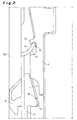
- FIG. 1 shown, rectangular storage and transport container 1 consists of a bottom 2, end walls 3 and longitudinal walls 4 and a lid consisting of two halves 5a, 5b cover.
- the cover halves 5a, 5b are pivotably hinged on the upper edge of the container and shown in their pivoted, latched with the container longitudinal walls 4 position.
- closure latches 6 provided on the lid halves 5a, 5b, one of which is provided on one end wall side of the container 1 in the lid halves 5a and 5b.
- the locking bolt 6, comprising a sliding sliding plate element, have at its in the installed position in the cover halves 5a and 5b upper side with a finger of a hand to be actuated handle part 7 and on its undersides a Einhakvorsprung 8 (see. Fig. 2 and the left half of Fig. 1 ) on.
- the Einhakvorsprünge 8 of the locking latch 7 engage in openings of the container upper edge.
- Fig. 1 and 2 and 3 serve the locking latch 6 in the pivoted position of the cover halves 5a and 5b at the same time to their tight-fitting latching with the container longitudinal walls 4.
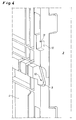
- the longitudinal walls 4 are to the handle parts 7 of the locking bolt 6 in their side areas to the widest extent contour-parallel and also provided with an undercut 9 formed locking receptacles 10 (see Fig. 4 and 5 ).
- the locking receptacles 10 are formed starting from their undercut 9 to the front or outside rising.
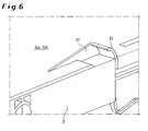
- the cover halves 5a and 5b are in the embodiment except with the locking bolts 6 continue with ergonomically shaped, in Fig. 6 shown as a detail handles 11 for gripping and pivoting the cover halves 5a, 5b provided in their respective position of use.
- the handles 11 can be used for additional locking of the pivoted-lid halves 5a and 5b in the container longitudinal walls 4.
- the handles 11 also associated with snap-in receptacles 12, which at its upper, the upper edge of the container 1 facing the end of a nose-like projection 13 have (see Fig. 4 and 5 ), the contour parallel to a slightly rounded head plate 14 (see. Fig. 6 ) of the handle 11 and the top plate 14 slightly overlaps in the locking position.
- the pivoted-lid halves 5a and 5b with or on the container longitudinal walls 4 are thus used in any case only on the cover halves existing components.
- the displaceable arrangement of the locking bolt is also used for automatic locking and unlocking, which is further promoted and supported by the matching shape of the interlocking locking elements. A tight, secure installation of the cover halves on the container longitudinal walls is ensured.
Description
Die Erfindung betrifft einen Lager- und Transportbehälter, umfassend einen aus zwei anscharnierten, nach außen wegschwenkbaren, in der Öffnungslage mit der Behälterwand verrastbaren Deckelhälften bestehenden Deckel, wobei die Deckelhälften mit mindestens einem verschiebbaren Verschlussriegel versehen sind, der oberhalb der Deckelhälfte ein Griffteil aufweist.The invention relates to a storage and transport container, comprising a lid hinged from two hinged, outwardly pivotable, in the open position with the container wall latched lid halves, wherein the lid halves are provided with at least one sliding latch, which has a handle above the lid half.
Ein Behälter bzw. Kasten mit einem Deckel, der durch einen Verschlussriegel die Behälteröffnung verschließend mit dem Behälterkorpus verriegelbar ist, ist durch die
Aus der
Der Erfindung liegt die Aufgabe zugrunde, einen Lager- und Transportbehälter bzw. Kasten der eingangs genannten Art zu schaffen, der eine Fixierung der geöffneten Deckelhälften in einfacher Weise und mit weniger Aufwand ermöglicht.The invention has for its object to provide a storage and transport container or box of the type mentioned above, which allows a fixation of the open lid halves in a simple manner and with less effort.
Diese Aufgabe wird erfindungsgemäß dadurch gelöst, daß die offen geschwenkten Deckelhälften unmittelbar mit dem Griffteil ihrer Verschlussriegel in die jeweilige Behälterwand einrasten. Indem somit dem Behälter bzw. den Deckelhälften immanente Bauteile, nämlich die vorhandenen Verschlussriegel, gleichzeitig auch zur Verrastung mit den Behälterwänden genutzt werden, bedarf es keiner zusätzlichen konstruktiven Maßnahmen an den Deckelhälften.This object is achieved in that the open-pivoted cover halves snap into the respective container wall directly with the handle part of its locking latch. By thus the container or the cover halves immanent components, namely the existing locking latch, are also used for locking with the container walls, it requires no additional design measures on the cover halves.
Eine bevorzugte Ausgestaltung der Erfindung sieht vor, daß den Verschlussriegeln in der Behälterwand zugeordnete Rastaufnahmen mit einem Hinterschnitt ausgebildet sind. Die aufgeschwenkten Deckelhälften brauchen lediglich an die Behälterlängswand gedrückt zu werden, wobei sich die Verschlussriegel beim Eintauchen in die Rastaufnahmen selbsttätig hochschieben bzw. verlagern und sukzessive in den eingebrachten Hinterschnitt eingreifen und verrasten, was sich durch leichtes An- bzw. Gegendrücken der Deckelhälfte einfach erreichen lässt. Zum Verschwenken der Deckelhälften in die Schließlage lässt sich die Verrastung der Griffteile der Verschlussriegel in den Rastaufnahmen ebenso leicht aufheben, weil die Konturgebung der Rastaufnahmen über die Griffteile die Verschiebung der Verschlussriegel bewirken, so daß sich die Griffteile durch eine nach oben gerichtete Bewegung sukzessive aus den Hinterschnitten lösen und in der Folge völlig freikommen.A preferred embodiment of the invention provides that the locking bolts in the container wall associated latching receptacles are formed with an undercut. The pivoted-lid halves need only be pressed against the container longitudinal wall, wherein the locking latch when dipping into the detent shots automatically move up or relocate and successively engage in the introduced undercut and lock, which can be easily achieved by gently pressing or counter-pressing the lid half , For pivoting the cover halves in the closed position, the locking of the handle parts of the locking bolt in the locking receptacles can just as easily cancel, because the contouring of the locking receptacles on the handle parts cause the displacement of the locking bolt, so that the handle parts by an upward movement successively from the Undo undercuts and release completely in the episode.
Wenn an den Deckelhälften angeordnete Handgriffe ebenfalls in die jeweilige Behälterwand einrasten, wobei den Handgriffen dort zugeordnete Rastaufnahmen vorteilhaft als nasenartige, daß vordere Handgriffende übergreifende Vorsprünge ausgebildet sind, lässt sich eine zusätzliche Verrastung bzw. Fixierung erreichen. Auch für diese zusätzliche Verrastung werden somit an den Deckelhälften ohnehin vorhandene Bauteile genutzt.When arranged on the cover halves handles also engage in the respective container wall, wherein the handles there associated latching receptacles advantageous as a nose-like that front handle end cross-projections are formed, can be achieved additional locking or fixation. Also for this additional locking thus existing components are used anyway on the cover halves.
Es wird in jedem Fall, d.h. sowohl mit der Verschlussriegel-Verrastung als auch bei der Kombination mit der Handgriff-Verrastung eine eng an den Behälterkorpus anliegende Fixierung und Sicherung der Deckelhälften in dieser Lage erreicht. Das wird vorzugsweise noch dadurch begünstigt, daß die Rastaufnahmen erfindungsgemäß zumindest bereichsweise konturparallel zu dem Verschlussriegel bzw. dem Handgriff ausgebildet sind. Die Behälter können daher nahe beieinander aufgestellt bzw. gelagert werden.It will in any case, i. achieved both with the locking latch locking and in combination with the handle latching a tight fitting to the container body fixation and securing the cover halves in this position. This is preferably favored by the fact that the locking receptacles according to the invention are formed at least partially contour-parallel to the locking bolt or the handle. The containers can therefore be placed close to each other or stored.
Weitere Einzelheiten und Merkmale der Erfindung ergeben sich aus den Ansprüchen und der nachfolgenden Ausführung eines in den Zeichnungen dargestellten Ausführungsbeispiels der Erfindung. Es zeigen:
- Fig. 1
- einen Lager- und Transportbehälter von einer Stirnwand her gesehen mit aufgeklappten bzw. weggeschwenkten und in den Behälterlängswänden verrasteten Deckelhälften;
- Fig. 2
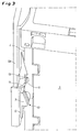
- als Einzelheit des Behälters nach
Fig. 1 die Verrastung der linken Deckelhälfte in der angrenzenden Behälterlängswand; - Fig. 3
- die Einzelheit der
Fig. 2 in einer perspektivischen Darstellung; - Fig. 4
- als Einzelheit in einer perspektivischen Vorderansicht die in die Behälterlängswand eingearbeiteten Rastaufnahmen;
- Fig. 5
- die Einzelheit der
Fig. 4 aus einer etwas anderen Perspektive; und - Fig. 6
- als Einzelheit in einer perspektivischen Darstellung einen an den Deckelhälften ausgebildeten, ergonomischen Handgriff.
- Fig. 1
- a storage and transport container seen from an end wall with unfolded or weggeschwenkten and latched in the container longitudinal walls lid halves;
- Fig. 2
- as a detail of the container
Fig. 1 the locking of the left lid half in the adjacent container longitudinal wall; - Fig. 3
- the detail of
Fig. 2 in a perspective view; - Fig. 4
- as a detail in a perspective front view of the incorporated into the container longitudinal wall locking receptacles;
- Fig. 5
- the detail of
Fig. 4 from a slightly different perspective; and - Fig. 6
- as a detail in a perspective view formed on the cover halves, ergonomic handle.
Ein in
Die Verschlussriegel 6, umfassend ein verschiebbares Gleitplattenelement, weisen an ihrer in der Einbaulage in den Deckelhälften 5a bzw. 5b oberen Seite ein mit einem Finger einer Hand zu betätigendes Griffteil 7 und an ihren Unterseiten einen Einhakvorsprung 8 (vgl.
Wie den
Die Deckelhälften 5a bzw. 5b sind im Ausführungsbeispiel außer mit den Verschlussriegeln 6 weiterhin auch mit ergonomisch geformten, in
Zur Fixierung der aufgeschwenkten Deckelhälften 5a bzw. 5b mit bzw. an den Behälterlängswänden 4 dienen somit in jedem Fall nur an den Deckelhälften ohnehin vorhandene Bauteile. Hierbei wird insbesondere die verschiebliche Anordnung der Verschlussriegel auch zum selbsttätigen Ver- und Entrasten genutzt, was noch durch die aufeinander angepasste Formgebung der ineinander greifenden Rastelemente begünstigt und unterstützt wird. Eine enge, sichere Anlage der Deckelhälften an den Behälterlängswänden wird gewährleistet.For fixing the pivoted-
Claims (5)
- Storage and transport container (1), comprising a lid consisting of two hinged lid halves (5a, 5b) which can be pivoted outwards and locked to the container wall (4) in the opening position, wherein the lid halves (5a, 5b) are provided with at least one displaceable closure bar (6) which has a grip part (7) above the lid half (5a, 5b),
characterised
in that the lid halves (5a, 5b) which have been pivoted open lock directly into the respective container wall (4) with the grip part (7) of their closure bar (6). - Storage and transport container according to Claim 1,
characterised
in that the locking recesses (10) associated with the grip parts (7) of the closure bar (6) in the container wall (4) are configured with an undercut (9). - Storage and transport container according to Claim 1 or 2,
characterised
in that handles (11) which are arranged on the lid halves (5a, 5b) lock into the respective container wall (4). - Storage and transport container according to Claim 3,
characterised
in that the locking recesses (12) associated with the handles (11) in the container wall (4) are configured as nose-like projections (13) which grasp the front end of the handle. - Storage and transport container according to one of Claims 1 to 4,
characterised
in that the locking recesses (10; 12) are configured to be at least in some areas parallel in contour to the grip part (7) of the closure bar (6) or to the handle (11).
Applications Claiming Priority (4)
| Application Number | Priority Date | Filing Date | Title |
|---|---|---|---|
| DE202004006398U | 2004-04-20 | ||
| DE202004006398 | 2004-04-20 | ||
| DE202005000845U | 2005-01-18 | ||
| DE200520000845 DE202005000845U1 (en) | 2004-04-20 | 2005-01-18 | Storage and transport container or box has lid halves that latch directly with handle parts of their closable lock elements in respective container walls when pivoted open |
Publications (2)
| Publication Number | Publication Date |
|---|---|
| EP1588955A1 EP1588955A1 (en) | 2005-10-26 |
| EP1588955B1 true EP1588955B1 (en) | 2008-09-17 |
Family
ID=34934167
Family Applications (1)
| Application Number | Title | Priority Date | Filing Date |
|---|---|---|---|
| EP20050005199 Active EP1588955B1 (en) | 2004-04-20 | 2005-03-10 | Storage and transport container |
Country Status (2)
| Country | Link |
|---|---|
| US (1) | US7448513B2 (en) |
| EP (1) | EP1588955B1 (en) |
Families Citing this family (3)
| Publication number | Priority date | Publication date | Assignee | Title |
|---|---|---|---|---|
| DE202004017452U1 (en) * | 2004-11-11 | 2005-02-17 | Fritz Schäfer GmbH | Foldable storage and transport container or box |
| US7967162B2 (en) * | 2007-04-18 | 2011-06-28 | John D. Brush & Co., Inc. | Double-walled blow-molded container including an undercut feature |
| US20090173744A1 (en) * | 2008-01-03 | 2009-07-09 | Hassell Jon P | Container with lid |
Family Cites Families (7)
| Publication number | Priority date | Publication date | Assignee | Title |
|---|---|---|---|---|
| US3850464A (en) * | 1973-05-23 | 1974-11-26 | R Bisbing | Slam-latch |
| US4161261A (en) * | 1978-05-05 | 1979-07-17 | Menasha Corporation | Security container |
| CH656854A5 (en) * | 1982-09-22 | 1986-07-31 | Utz Ag Georg | CONTAINER WITH LID AND LOCKING LATCH. |
| US5501503A (en) * | 1994-03-24 | 1996-03-26 | Thayer; Henry | Vehicular door |
| US6179156B1 (en) * | 2000-02-04 | 2001-01-30 | Rehrig Pacific Company | Multi-purpose container |
| DE50304039D1 (en) | 2002-12-13 | 2006-08-10 | Utz Georg Holding Ag | stacking containers |
| USD493282S1 (en) * | 2003-05-14 | 2004-07-27 | Georg Utz Holding, Ag | Plastic storage box |
-
2005
- 2005-03-10 EP EP20050005199 patent/EP1588955B1/en active Active
- 2005-04-12 US US11/108,035 patent/US7448513B2/en active Active
Also Published As
| Publication number | Publication date |
|---|---|
| US7448513B2 (en) | 2008-11-11 |
| US20050233621A1 (en) | 2005-10-20 |
| EP1588955A1 (en) | 2005-10-26 |
Similar Documents
| Publication | Publication Date | Title |
|---|---|---|
| EP2189381B1 (en) | Portable transport or storage container | |
| EP1305145B1 (en) | Tool box | |
| EP1516703B1 (en) | Stackable toolbox | |
| EP2226265B1 (en) | Container with a cover and a locking device | |
| EP3484664B1 (en) | Stackable system container | |
| DE202005017057U1 (en) | Food container has slider with fasteners for latching cover to bowl, such that fasteners create contact pressure between cover and edge of bowl | |
| EP2703310A1 (en) | Container | |
| DE102008047859A1 (en) | large containers | |
| EP1475008B1 (en) | Suitcase | |
| EP1533244B1 (en) | Container with pivotally mounted cover | |
| DE3247308C2 (en) | Locking mechanism for a cassette provided with a lid | |
| EP1588955B1 (en) | Storage and transport container | |
| EP0388504A1 (en) | Plastics crate in two parts | |
| EP0455935B1 (en) | Lockable rubbish bin | |
| EP3997004B1 (en) | Container having a lockable cover | |
| EP1197621A1 (en) | Locking arrangement for storage bin | |
| DE1553443A1 (en) | Snap lock with locking device | |
| DE202005000845U1 (en) | Storage and transport container or box has lid halves that latch directly with handle parts of their closable lock elements in respective container walls when pivoted open | |
| DE102008037009A1 (en) | Tool box for storing hand tool, has carrying device comprising engaging element and carrying element, where carrying element is rotated to rotate engaging element for turning receiver | |
| CH695684A5 (en) | Food container especially for tarts has cover fixable on base plate by two or more diametrically opposite releasable fixing bolts | |
| DE20314261U1 (en) | Plastics storage and transport crate has sprung slides with locking tongues sliding in guide housings on lid | |
| EP3817894B1 (en) | Storage device | |
| DE10118503B4 (en) | Container, in particular postal container | |
| DE202007006158U1 (en) | Locking for concrete cabinets and container boxes | |
| WO2020212012A1 (en) | Folding container |
Legal Events
| Date | Code | Title | Description |
|---|---|---|---|
| PUAI | Public reference made under article 153(3) epc to a published international application that has entered the european phase |
Free format text: ORIGINAL CODE: 0009012 |
|
| AK | Designated contracting states |
Kind code of ref document: A1 Designated state(s): AT BE BG CH CY CZ DE DK EE ES FI FR GB GR HU IE IS IT LI LT LU MC NL PL PT RO SE SI SK TR |
|
| AX | Request for extension of the european patent |
Extension state: AL BA HR LV MK YU |
|
| 17P | Request for examination filed |
Effective date: 20060420 |
|
| AKX | Designation fees paid |
Designated state(s): AT BE BG CH CY CZ DE DK EE ES FI FR GB GR HU IE IS IT LI LT LU MC NL PL PT RO SE SI SK TR |
|
| GRAP | Despatch of communication of intention to grant a patent |
Free format text: ORIGINAL CODE: EPIDOSNIGR1 |
|
| GRAS | Grant fee paid |
Free format text: ORIGINAL CODE: EPIDOSNIGR3 |
|
| GRAA | (expected) grant |
Free format text: ORIGINAL CODE: 0009210 |
|
| AK | Designated contracting states |
Kind code of ref document: B1 Designated state(s): AT BE BG CH CY CZ DE DK EE ES FI FR GB GR HU IE IS IT LI LT LU MC NL PL PT RO SE SI SK TR |
|
| REG | Reference to a national code |
Ref country code: GB Ref legal event code: FG4D Free format text: NOT ENGLISH |
|
| REG | Reference to a national code |
Ref country code: CH Ref legal event code: EP |
|
| REG | Reference to a national code |
Ref country code: IE Ref legal event code: FG4D Free format text: LANGUAGE OF EP DOCUMENT: GERMAN |
|
| REF | Corresponds to: |
Ref document number: 502005005372 Country of ref document: DE Date of ref document: 20081030 Kind code of ref document: P |
|
| REG | Reference to a national code |
Ref country code: CH Ref legal event code: NV Representative=s name: SCHMAUDER & PARTNER AG PATENTANWALTSBUERO |
|
| PG25 | Lapsed in a contracting state [announced via postgrant information from national office to epo] |
Ref country code: LT Free format text: LAPSE BECAUSE OF FAILURE TO SUBMIT A TRANSLATION OF THE DESCRIPTION OR TO PAY THE FEE WITHIN THE PRESCRIBED TIME-LIMIT Effective date: 20080917 |
|
| PG25 | Lapsed in a contracting state [announced via postgrant information from national office to epo] |
Ref country code: SI Free format text: LAPSE BECAUSE OF FAILURE TO SUBMIT A TRANSLATION OF THE DESCRIPTION OR TO PAY THE FEE WITHIN THE PRESCRIBED TIME-LIMIT Effective date: 20080917 Ref country code: FI Free format text: LAPSE BECAUSE OF FAILURE TO SUBMIT A TRANSLATION OF THE DESCRIPTION OR TO PAY THE FEE WITHIN THE PRESCRIBED TIME-LIMIT Effective date: 20080917 |
|
| REG | Reference to a national code |
Ref country code: IE Ref legal event code: FD4D |
|
| PG25 | Lapsed in a contracting state [announced via postgrant information from national office to epo] |
Ref country code: BG Free format text: LAPSE BECAUSE OF FAILURE TO SUBMIT A TRANSLATION OF THE DESCRIPTION OR TO PAY THE FEE WITHIN THE PRESCRIBED TIME-LIMIT Effective date: 20081217 Ref country code: ES Free format text: LAPSE BECAUSE OF FAILURE TO SUBMIT A TRANSLATION OF THE DESCRIPTION OR TO PAY THE FEE WITHIN THE PRESCRIBED TIME-LIMIT Effective date: 20081228 |
|
| PG25 | Lapsed in a contracting state [announced via postgrant information from national office to epo] |
Ref country code: CZ Free format text: LAPSE BECAUSE OF FAILURE TO SUBMIT A TRANSLATION OF THE DESCRIPTION OR TO PAY THE FEE WITHIN THE PRESCRIBED TIME-LIMIT Effective date: 20080917 Ref country code: IS Free format text: LAPSE BECAUSE OF FAILURE TO SUBMIT A TRANSLATION OF THE DESCRIPTION OR TO PAY THE FEE WITHIN THE PRESCRIBED TIME-LIMIT Effective date: 20090117 Ref country code: PT Free format text: LAPSE BECAUSE OF FAILURE TO SUBMIT A TRANSLATION OF THE DESCRIPTION OR TO PAY THE FEE WITHIN THE PRESCRIBED TIME-LIMIT Effective date: 20090217 Ref country code: RO Free format text: LAPSE BECAUSE OF FAILURE TO SUBMIT A TRANSLATION OF THE DESCRIPTION OR TO PAY THE FEE WITHIN THE PRESCRIBED TIME-LIMIT Effective date: 20080917 Ref country code: SK Free format text: LAPSE BECAUSE OF FAILURE TO SUBMIT A TRANSLATION OF THE DESCRIPTION OR TO PAY THE FEE WITHIN THE PRESCRIBED TIME-LIMIT Effective date: 20080917 |
|
| PLBE | No opposition filed within time limit |
Free format text: ORIGINAL CODE: 0009261 |
|
| STAA | Information on the status of an ep patent application or granted ep patent |
Free format text: STATUS: NO OPPOSITION FILED WITHIN TIME LIMIT |
|
| PG25 | Lapsed in a contracting state [announced via postgrant information from national office to epo] |
Ref country code: IE Free format text: LAPSE BECAUSE OF FAILURE TO SUBMIT A TRANSLATION OF THE DESCRIPTION OR TO PAY THE FEE WITHIN THE PRESCRIBED TIME-LIMIT Effective date: 20080917 Ref country code: DK Free format text: LAPSE BECAUSE OF FAILURE TO SUBMIT A TRANSLATION OF THE DESCRIPTION OR TO PAY THE FEE WITHIN THE PRESCRIBED TIME-LIMIT Effective date: 20080917 Ref country code: EE Free format text: LAPSE BECAUSE OF FAILURE TO SUBMIT A TRANSLATION OF THE DESCRIPTION OR TO PAY THE FEE WITHIN THE PRESCRIBED TIME-LIMIT Effective date: 20080917 |
|
| REG | Reference to a national code |
Ref country code: CH Ref legal event code: PCAR Free format text: SCHMAUDER & PARTNER AG PATENT- UND MARKENANWAELTE VSP;ZWAENGIWEG 7;8038 ZUERICH (CH) |
|
| 26N | No opposition filed |
Effective date: 20090618 |
|
| PG25 | Lapsed in a contracting state [announced via postgrant information from national office to epo] |
Ref country code: IT Free format text: LAPSE BECAUSE OF FAILURE TO SUBMIT A TRANSLATION OF THE DESCRIPTION OR TO PAY THE FEE WITHIN THE PRESCRIBED TIME-LIMIT Effective date: 20080917 |
|
| PG25 | Lapsed in a contracting state [announced via postgrant information from national office to epo] |
Ref country code: MC Free format text: LAPSE BECAUSE OF NON-PAYMENT OF DUE FEES Effective date: 20090331 |
|
| PG25 | Lapsed in a contracting state [announced via postgrant information from national office to epo] |
Ref country code: SE Free format text: LAPSE BECAUSE OF FAILURE TO SUBMIT A TRANSLATION OF THE DESCRIPTION OR TO PAY THE FEE WITHIN THE PRESCRIBED TIME-LIMIT Effective date: 20081217 |
|
| PG25 | Lapsed in a contracting state [announced via postgrant information from national office to epo] |
Ref country code: PL Free format text: LAPSE BECAUSE OF FAILURE TO SUBMIT A TRANSLATION OF THE DESCRIPTION OR TO PAY THE FEE WITHIN THE PRESCRIBED TIME-LIMIT Effective date: 20080917 |
|
| PG25 | Lapsed in a contracting state [announced via postgrant information from national office to epo] |
Ref country code: GR Free format text: LAPSE BECAUSE OF FAILURE TO SUBMIT A TRANSLATION OF THE DESCRIPTION OR TO PAY THE FEE WITHIN THE PRESCRIBED TIME-LIMIT Effective date: 20081218 |
|
| PG25 | Lapsed in a contracting state [announced via postgrant information from national office to epo] |
Ref country code: LU Free format text: LAPSE BECAUSE OF NON-PAYMENT OF DUE FEES Effective date: 20090310 |
|
| PG25 | Lapsed in a contracting state [announced via postgrant information from national office to epo] |
Ref country code: HU Free format text: LAPSE BECAUSE OF FAILURE TO SUBMIT A TRANSLATION OF THE DESCRIPTION OR TO PAY THE FEE WITHIN THE PRESCRIBED TIME-LIMIT Effective date: 20090318 |
|
| PG25 | Lapsed in a contracting state [announced via postgrant information from national office to epo] |
Ref country code: TR Free format text: LAPSE BECAUSE OF FAILURE TO SUBMIT A TRANSLATION OF THE DESCRIPTION OR TO PAY THE FEE WITHIN THE PRESCRIBED TIME-LIMIT Effective date: 20080917 |
|
| PG25 | Lapsed in a contracting state [announced via postgrant information from national office to epo] |
Ref country code: CY Free format text: LAPSE BECAUSE OF FAILURE TO SUBMIT A TRANSLATION OF THE DESCRIPTION OR TO PAY THE FEE WITHIN THE PRESCRIBED TIME-LIMIT Effective date: 20080917 |
|
| REG | Reference to a national code |
Ref country code: FR Ref legal event code: PLFP Year of fee payment: 12 |
|
| REG | Reference to a national code |
Ref country code: FR Ref legal event code: PLFP Year of fee payment: 13 |
|
| REG | Reference to a national code |
Ref country code: FR Ref legal event code: PLFP Year of fee payment: 14 |
|
| PGFP | Annual fee paid to national office [announced via postgrant information from national office to epo] |
Ref country code: NL Payment date: 20190320 Year of fee payment: 15 Ref country code: AT Payment date: 20190321 Year of fee payment: 15 |
|
| PGFP | Annual fee paid to national office [announced via postgrant information from national office to epo] |
Ref country code: GB Payment date: 20200323 Year of fee payment: 16 |
|
| PGFP | Annual fee paid to national office [announced via postgrant information from national office to epo] |
Ref country code: CH Payment date: 20200319 Year of fee payment: 16 Ref country code: BE Payment date: 20200319 Year of fee payment: 16 |
|
| PGFP | Annual fee paid to national office [announced via postgrant information from national office to epo] |
Ref country code: FR Payment date: 20200319 Year of fee payment: 16 |
|
| REG | Reference to a national code |
Ref country code: NL Ref legal event code: MM Effective date: 20200401 |
|
| REG | Reference to a national code |
Ref country code: AT Ref legal event code: MM01 Ref document number: 408563 Country of ref document: AT Kind code of ref document: T Effective date: 20200310 |
|
| PG25 | Lapsed in a contracting state [announced via postgrant information from national office to epo] |
Ref country code: NL Free format text: LAPSE BECAUSE OF NON-PAYMENT OF DUE FEES Effective date: 20200401 |
|
| PG25 | Lapsed in a contracting state [announced via postgrant information from national office to epo] |
Ref country code: AT Free format text: LAPSE BECAUSE OF NON-PAYMENT OF DUE FEES Effective date: 20200310 |
|
| REG | Reference to a national code |
Ref country code: CH Ref legal event code: PL |
|
| GBPC | Gb: european patent ceased through non-payment of renewal fee |
Effective date: 20210310 |
|
| REG | Reference to a national code |
Ref country code: BE Ref legal event code: MM Effective date: 20210331 |
|
| PG25 | Lapsed in a contracting state [announced via postgrant information from national office to epo] |
Ref country code: GB Free format text: LAPSE BECAUSE OF NON-PAYMENT OF DUE FEES Effective date: 20210310 Ref country code: FR Free format text: LAPSE BECAUSE OF NON-PAYMENT OF DUE FEES Effective date: 20210331 Ref country code: LI Free format text: LAPSE BECAUSE OF NON-PAYMENT OF DUE FEES Effective date: 20210331 Ref country code: CH Free format text: LAPSE BECAUSE OF NON-PAYMENT OF DUE FEES Effective date: 20210331 |
|
| PG25 | Lapsed in a contracting state [announced via postgrant information from national office to epo] |
Ref country code: BE Free format text: LAPSE BECAUSE OF NON-PAYMENT OF DUE FEES Effective date: 20210331 |
|
| P01 | Opt-out of the competence of the unified patent court (upc) registered |
Effective date: 20230517 |
|
| PGFP | Annual fee paid to national office [announced via postgrant information from national office to epo] |
Ref country code: DE Payment date: 20230821 Year of fee payment: 19 |