EP1588945B1 - Method and device quality controlling packets - Google Patents
Method and device quality controlling packets Download PDFInfo
- Publication number
- EP1588945B1 EP1588945B1 EP05103055.9A EP05103055A EP1588945B1 EP 1588945 B1 EP1588945 B1 EP 1588945B1 EP 05103055 A EP05103055 A EP 05103055A EP 1588945 B1 EP1588945 B1 EP 1588945B1
- Authority
- EP
- European Patent Office
- Prior art keywords
- packet
- given
- line
- given portion
- edge
- Prior art date
- Legal status (The legal status is an assumption and is not a legal conclusion. Google has not performed a legal analysis and makes no representation as to the accuracy of the status listed.)
- Not-in-force
Links
Images


Classifications
-
- B—PERFORMING OPERATIONS; TRANSPORTING
- B65—CONVEYING; PACKING; STORING; HANDLING THIN OR FILAMENTARY MATERIAL
- B65B—MACHINES, APPARATUS OR DEVICES FOR, OR METHODS OF, PACKAGING ARTICLES OR MATERIALS; UNPACKING
- B65B19/00—Packaging rod-shaped or tubular articles susceptible to damage by abrasion or pressure, e.g. cigarettes, cigars, macaroni, spaghetti, drinking straws or welding electrodes
- B65B19/28—Control devices for cigarette or cigar packaging machines
-
- G—PHYSICS
- G01—MEASURING; TESTING
- G01N—INVESTIGATING OR ANALYSING MATERIALS BY DETERMINING THEIR CHEMICAL OR PHYSICAL PROPERTIES
- G01N21/00—Investigating or analysing materials by the use of optical means, i.e. using sub-millimetre waves, infrared, visible or ultraviolet light
- G01N21/84—Systems specially adapted for particular applications
- G01N21/85—Investigating moving fluids or granular solids
-
- G—PHYSICS
- G01—MEASURING; TESTING
- G01N—INVESTIGATING OR ANALYSING MATERIALS BY DETERMINING THEIR CHEMICAL OR PHYSICAL PROPERTIES
- G01N21/00—Investigating or analysing materials by the use of optical means, i.e. using sub-millimetre waves, infrared, visible or ultraviolet light
- G01N21/84—Systems specially adapted for particular applications
- G01N21/88—Investigating the presence of flaws or contamination
- G01N21/8851—Scan or image signal processing specially adapted therefor, e.g. for scan signal adjustment, for detecting different kinds of defects, for compensating for structures, markings, edges
-
- G—PHYSICS
- G07—CHECKING-DEVICES
- G07C—TIME OR ATTENDANCE REGISTERS; REGISTERING OR INDICATING THE WORKING OF MACHINES; GENERATING RANDOM NUMBERS; VOTING OR LOTTERY APPARATUS; ARRANGEMENTS, SYSTEMS OR APPARATUS FOR CHECKING NOT PROVIDED FOR ELSEWHERE
- G07C3/00—Registering or indicating the condition or the working of machines or other apparatus, other than vehicles
- G07C3/14—Quality control systems
- G07C3/146—Quality control systems during manufacturing process
-
- B—PERFORMING OPERATIONS; TRANSPORTING
- B31—MAKING ARTICLES OF PAPER, CARDBOARD OR MATERIAL WORKED IN A MANNER ANALOGOUS TO PAPER; WORKING PAPER, CARDBOARD OR MATERIAL WORKED IN A MANNER ANALOGOUS TO PAPER
- B31B—MAKING CONTAINERS OF PAPER, CARDBOARD OR MATERIAL WORKED IN A MANNER ANALOGOUS TO PAPER
- B31B50/00—Making rigid or semi-rigid containers, e.g. boxes or cartons
- B31B50/006—Controlling; Regulating; Measuring; Improving safety
Definitions
- the present invention relates to a method and device for quality controlling a packet; to a packet; and to a relative blank.
- the present invention may be used to advantage in packing cigarettes, to which the following description refers purely by way of example.
- Packets produced on a packing machine are normally quality controlled to determine any defects, in particular, stains, scratches, or dents; and any faulty packets are subsequently rejected.
- Patent US 4,912,554 a packet is fed along a path through a quality control station where television cameras acquire an image of the packet; and the image is compared with a reference image to determine whether or not the packet is to be rejected.
- US 5877506 discloses a device, which is designed to monitor blanks and comprises a source of infrared radiation. Such a device is designed to monitor only the contours of the blanks in order to verify the supply of the correct blanks, when there is a change in the type of packaging to be manufactured, and the correct positioning of the blanks.
- the device disclosed in US 5877506 is not designed to control the quality of the blanks and is not designed to monitor surfaces of the blanks.
- Number 1 in Figure 1 indicates as a whole a device for quality controlling a "rigid" packet 2 of cigarettes ( Figure 3 ).
- Packet 2 comprises a cup-shaped body 3, and a lid 4 hinged to cup-shaped body 3.
- Cup-shaped body 3 comprises a front wall 5, two lateral walls 6 (only one shown in Figure 3 ), a bottom wall (now shown), and a rear wall (not shown).
- Lid 4 comprises a front wall 5a, two lateral walls 6a (only one shown in Figure 3 ), a top wall 7, and a rear wall (not shown).
- Lateral walls 6 and 6a are connected to respective front walls 5 and 5a and to the respective rear walls (not shown) by relative longitudinal edges 8.
- Front wall 5a and the rear wall (not shown) of lid 4 are connected to top wall 7 by relative edges 9; and front wall 5 is connected to the bottom wall (not shown) by an edge 10.
- Packet 2 is formed from a substantially flat blank 11 ( Figure 4 ) comprising a central portion 12, and a number of lateral panels 13 located symmetrically on opposite sides of portion 12.
- Portion 12 comprises a number of panels aligned lengthwise of blank 11; each panel 13 is connected to portion 12 by a preformed fold line 14; and, once folded, fold lines 14 correspond to edges 8 of packet 2.
- Blank 11 has a grid 15 comprising a number of parallel longitudinal lines 16, and a number of parallel lines 17 crosswise, in particular, perpendicular, to lines 16.
- Lines 16 and 17 are invisible to the naked eye, and comprise special pigments detectable optically at a given wavelength outside the visible range, in particular at a wavelength in the ultraviolet range.
- Device 1 ( Figure 1 ) comprises a transfer unit 18 for feeding packet 2 along a path P through two quality control stations 19 and 20.
- Device 1 also comprises two conveyors 21 and 22, each having a suction belt 23 positioned on edge and looped about two vertical-axis pulleys 24.
- Conveyor 21 receives packet 2 from an input station 25, and feeds packet 2 through quality control station 19 to conveyor 22; and conveyor 22 feeds packet 2 through quality control station 20 to an output station 26.
- Two detecting units 27 and 28 are located at quality control stations 19 and 20 respectively, and each comprise an optical detector 29, 30, and an electromagnetic radiation source 31.
- Optical detectors 29 and 30 acquire data relative to grid 15 by receiving electromagnetic radiation at said given wavelength.
- two inclined mirrors 32 are located on opposite sides of conveyor 21 at quality control station 19, to enable optical detector 29 to analyze lateral walls 6 and 6a of packet 2.
- Device 1 also comprises a central control unit 33 which receives the data acquired by detecting units 27 and 28, and in turn comprises a comparing unit 34 for comparing the acquired data with reference data. On the basis of the comparison between the acquired and reference data, central control unit 33 activates a known reject device 35 (shown schematically in Figure 1 ) located immediately downstream from device 1 and for eliminating any faulty packets downstream from conveyor 22.
- a known reject device 35 shown schematically in Figure 1
- sources 31 emit electromagnetic radiation to bring the pigments to an excited state, decaying from which the pigments themselves emit electromagnetic radiation at said given wavelength outside the visible range.
- optical detectors 29 and 30 detect the shape and/or position of various areas of grid 15 and/or the intensity of the electromagnetic radiation, at the given wavelength, from the areas of grid 15.
- the electromagnetic radiation emitted by sources 31 and the aforementioned pigments may have different wavelengths.
- the electromagnetic radiation emitted by sources 31 and the aforementioned pigments have indeed different wavelengths, as optical detectors 29 and 30 detects electromagnetic radiation at the aforementioned given wavelength, noise due to, for example, radiation simply reflected by packet 2 is disregarded; as a consequence, the detection of data is more precise.
- the detected shape, position, and/or intensity are compared by comparing unit 34 with a reference shape, position, and/or intensity; and, in the event the difference between the detected and reference data exceeds given threshold values, central control unit 33 activates reject device 35.
- Optical detectors 29 and 30 preferably each comprise known area scales for detecting electromagnetic radiation, at the given wavelength, along scan lines 36.
- Figure 15 shows an area of grid 15, and the corresponding area scale response along scan line 36.
- the y axis shows the position along the scan line, and the x axis the intensity of the relative pixels.
- the comparing unit compares the positions, heights, and/or shapes of the peaks in Figure 15 with reference positions, heights, and/or shapes.
- Device 1 as described above allows changes to be made to the graphics (artwork, brands, and/or colours) on the outside of packet 2 (e.g. so-called "brand changes") without changing the reference data, and also provides for accurately determining the condition of packet 2, even in areas of packet 2 bearing complex and/or highly coloured images.
- optical detectors 29 and 30 only detect electromagnetic radiation at said given wavelength outside the visible range, whatever is picked up by optical detectors 29 and 30 is unaffected by the graphics on the outside of packet 2.
- FIGS 5 to 14 show alternative embodiments of packet 2 and relative blank 11.
- packets 2 in Figures 5 to 9 are substantially similar to packet 2 described above, except that grid 15 is replaced by one or more given portions 37 of various forms and comprising said pigments.
- Grid 15 is preferably stamped on blank 11 off the packing machine, i.e. at the packing material manufacturer's plant or paper mill.
- the grid may be stamped on the blank by means of a stamping device upstream from the packing machine.
- the Figure 5 packet 2 formed from the Figure 10 blank, comprises one portion 37 on lateral wall 6a of lid 4.
- optical detector 29 can detect portion 37 directly, and not only by means of one of mirrors 32.
- portion 37 is hatched.
- portion 37 extends along the edges of packet 2. As shown in Figure 11 , portion 37 extends at least partly along the edge of blank 11. In Figures 6 and 11 , portion 37 is hatched.
- portion 37 comprises two substantially perpendicular lines on front wall 5, one extending from one longitudinal edge 8 to the other longitudinal edge 8, and the other extending from edge 9 to edge 10.
- portion 37 is shown by bold lines.
- portion 37 comprises two substantially perpendicular lines, a first extending on front wall 5, lateral walls 6, and the rear wall (not shown in Figure 7 ) of cup-shaped body 3, and a second extending on front walls 5 and 5a, on the bottom and rear walls (not shown in Figure 7 ) of cup-shaped body 3, and on top wall 7 and the rear wall (not shown in Figure 7 ) of lid 4.
- portion 37 is shown by bold lines.
- the Figure 9 packet 2 formed from the Figure 14 blank 11 has a portion 37 comprising a number of lines, which extend along the edges of packet 2, and which, from the corners, intersect on each wall 5, 5a, 6, 6a, 7, each of the rear walls (not shown), and the bottom wall (not shown).
- portion 37 is shown by bold lines.
Description
- The present invention relates to a method and device for quality controlling a packet; to a packet; and to a relative blank.
- The present invention may be used to advantage in packing cigarettes, to which the following description refers purely by way of example.
- Packets produced on a packing machine are normally quality controlled to determine any defects, in particular, stains, scratches, or dents; and any faulty packets are subsequently rejected.
- In Patent
US 4,912,554 , a packet is fed along a path through a quality control station where television cameras acquire an image of the packet; and the image is compared with a reference image to determine whether or not the packet is to be rejected. - Though efficient, the known quality control system described above has been found to fall short in some respects in terms of versatility and sensitivity. In particular, whenever changes are made to the graphics (artwork, brands, and/or colours) on the outside of the packets (e.g. so-called "brand changes"), changes must also be made to the reference image. Moreover, in areas of the packet bearing complex and/or highly coloured images, defects such as scratches or dents are especially difficult to detect. In other words, the artwork and colours on the packet act as noise during detection.
-
US 5877506 discloses a device, which is designed to monitor blanks and comprises a source of infrared radiation. Such a device is designed to monitor only the contours of the blanks in order to verify the supply of the correct blanks, when there is a change in the type of packaging to be manufactured, and the correct positioning of the blanks. The device disclosed inUS 5877506 is not designed to control the quality of the blanks and is not designed to monitor surfaces of the blanks. - It is an object of the present invention to provide a method and device for quality controlling a packet, designed to eliminate, at least partially, the aforementioned drawbacks, and which at the same time are cheap and easy to implement.
- According to the present invention, there is provided a method of quality controlling packets, as claimed in
Claim 1 or in any one of the following Claims depending directly or indirectly onClaim 1. - According to the present invention, there is also provided a device for quality controlling packets, as claimed in
Claim 11 or in any one of the following Claims depending directly or indirectly onClaim 11 . - According to the present invention, there is also provided a packet, as claimed in
Claim Claim - According to the present invention, there is also provided a blank, as claimed in
Claim Claim - A number of non-limiting embodiments of the present invention will be described by way of example with reference to the accompanying drawings, in which:
-
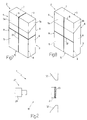
Figure 1 shows a view in perspective, with parts removed for clarity, of a device for quality controlling packets in accordance with the present invention; -
Figure 2 shows a larger-scale section along line II-II of theFigure 1 device; -
Figure 3 shows a front view in perspective of a packet of cigarettes in accordance with the present invention; -
Figure 4 shows a spread-out view of a blank by which to form theFigure 3 packet; -
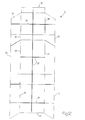
Figures 5 to 9 show front views in perspective of alternative embodiments of packets in accordance with the present invention; -
Figures 10 to 14 show spread-out views of blanks by which to form theFigure 5 to 9 packets respectively; -
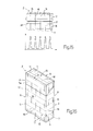
Figure 15 shows a portion of theFigure 3 packet and the corresponding response of a detecting device; -
Figure 16 shows a front view in perspective of a damagedFigure 3 packet. -
Number 1 inFigure 1 indicates as a whole a device for quality controlling a "rigid"packet 2 of cigarettes (Figure 3 ).Packet 2 comprises a cup-shaped body 3, and alid 4 hinged to cup-shaped body 3. Cup-shaped body 3 comprises afront wall 5, two lateral walls 6 (only one shown inFigure 3 ), a bottom wall (now shown), and a rear wall (not shown).Lid 4 comprises afront wall 5a, twolateral walls 6a (only one shown inFigure 3 ), atop wall 7, and a rear wall (not shown).Lateral walls front walls longitudinal edges 8.Front wall 5a and the rear wall (not shown) oflid 4 are connected totop wall 7 byrelative edges 9; andfront wall 5 is connected to the bottom wall (not shown) by anedge 10. -
Packet 2 is formed from a substantially flat blank 11 (Figure 4 ) comprising acentral portion 12, and a number oflateral panels 13 located symmetrically on opposite sides ofportion 12.Portion 12 comprises a number of panels aligned lengthwise of blank 11; eachpanel 13 is connected toportion 12 by apreformed fold line 14; and, once folded,fold lines 14 correspond toedges 8 ofpacket 2. -
Blank 11 has agrid 15 comprising a number of parallellongitudinal lines 16, and a number ofparallel lines 17 crosswise, in particular, perpendicular, tolines 16.Lines - Device 1 (
Figure 1 ) comprises atransfer unit 18 forfeeding packet 2 along a path P through twoquality control stations Device 1 also comprises twoconveyors suction belt 23 positioned on edge and looped about two vertical-axis pulleys 24.Conveyor 21 receivespacket 2 from aninput station 25, and feedspacket 2 throughquality control station 19 toconveyor 22; andconveyor 22feeds packet 2 throughquality control station 20 to anoutput station 26. - Two detecting
units quality control stations optical detector electromagnetic radiation source 31.Optical detectors grid 15 by receiving electromagnetic radiation at said given wavelength. - As shown more clearly in
Figure 2 , twoinclined mirrors 32 are located on opposite sides ofconveyor 21 atquality control station 19, to enableoptical detector 29 to analyzelateral walls packet 2. -
Device 1 also comprises acentral control unit 33 which receives the data acquired by detectingunits unit 34 for comparing the acquired data with reference data. On the basis of the comparison between the acquired and reference data,central control unit 33 activates a known reject device 35 (shown schematically inFigure 1 ) located immediately downstream fromdevice 1 and for eliminating any faulty packets downstream fromconveyor 22. - In actual use, when
packet 2 is located atquality control stations sources 31 emit electromagnetic radiation to bring the pigments to an excited state, decaying from which the pigments themselves emit electromagnetic radiation at said given wavelength outside the visible range. At this point,optical detectors grid 15 and/or the intensity of the electromagnetic radiation, at the given wavelength, from the areas ofgrid 15. - The electromagnetic radiation emitted by
sources 31 and the aforementioned pigments may have different wavelengths. In the case the electromagnetic radiation emitted bysources 31 and the aforementioned pigments have indeed different wavelengths, asoptical detectors packet 2 is disregarded; as a consequence, the detection of data is more precise. - The detected shape, position, and/or intensity are compared by comparing
unit 34 with a reference shape, position, and/or intensity; and, in the event the difference between the detected and reference data exceeds given threshold values,central control unit 33 activatesreject device 35. - In connection with the above, it should be pointed out that, in the
event packet 2 is dented, the shape and position of detected areas ofgrid 15 differ from the reference shape and position ofpacket 2 in perfect condition; and, in theevent packet 2 is scratched, the intensity of the electromagnetic radiation, at the given wavelength, of the scratched area ofgrid 15 is below the reference intensity.Figure 16 shows theFigure 3 packet 2 with a dent alongedge 10, and the relative distortedgrid 15. -
Optical detectors scan lines 36. By way of example,Figure 15 shows an area ofgrid 15, and the corresponding area scale response alongscan line 36. The y axis shows the position along the scan line, and the x axis the intensity of the relative pixels. In this case, the comparing unit compares the positions, heights, and/or shapes of the peaks inFigure 15 with reference positions, heights, and/or shapes. -
Device 1 as described above allows changes to be made to the graphics (artwork, brands, and/or colours) on the outside of packet 2 (e.g. so-called "brand changes") without changing the reference data, and also provides for accurately determining the condition ofpacket 2, even in areas ofpacket 2 bearing complex and/or highly coloured images. - In this connection, it should be pointed out that, since
optical detectors optical detectors packet 2. -
Figures 5 to 14 show alternative embodiments ofpacket 2 and relative blank 11. As can be seen,packets 2 inFigures 5 to 9 are substantially similar topacket 2 described above, except thatgrid 15 is replaced by one or more givenportions 37 of various forms and comprising said pigments. -
Grid 15 is preferably stamped on blank 11 off the packing machine, i.e. at the packing material manufacturer's plant or paper mill. Alternatively, the grid may be stamped on the blank by means of a stamping device upstream from the packing machine. - The
Figure 5 packet 2, formed from theFigure 10 blank, comprises oneportion 37 onlateral wall 6a oflid 4. In this case, in the event thelateral panel 13 partly definingwall 6a is not glued properly and is therefore partly raised,optical detector 29 can detectportion 37 directly, and not only by means of one ofmirrors 32. InFigures 5 and10 ,portion 37 is hatched. - In the
Figure 6 packet 2, formed from theFigure 11 blank 11,portion 37 extends along the edges ofpacket 2. As shown inFigure 11 ,portion 37 extends at least partly along the edge of blank 11. InFigures 6 and11 ,portion 37 is hatched. - In the
Figure 8 packet 2, formed from theFigure 13 blank 11,portion 37 comprises two substantially perpendicular lines onfront wall 5, one extending from onelongitudinal edge 8 to the otherlongitudinal edge 8, and the other extending fromedge 9 to edge 10. InFigures 8 and13 ,portion 37 is shown by bold lines. - In the
Figure 7 packet 2, formed from theFigure 12 blank 11,portion 37 comprises two substantially perpendicular lines, a first extending onfront wall 5,lateral walls 6, and the rear wall (not shown inFigure 7 ) of cup-shapedbody 3, and a second extending onfront walls Figure 7 ) of cup-shapedbody 3, and ontop wall 7 and the rear wall (not shown inFigure 7 ) oflid 4. InFigures 7 and12 ,portion 37 is shown by bold lines. - The
Figure 9 packet 2, formed from theFigure 14 blank 11, has aportion 37 comprising a number of lines, which extend along the edges ofpacket 2, and which, from the corners, intersect on eachwall Figures 9 and14 ,portion 37 is shown by bold lines. - Though the above description and accompanying drawings relate to a conventional hinged-lid packet of cigarettes, the teachings of the present invention obviously also apply to packets of cigarettes of any type, such as a hinged-lid packet with rounded or bevelled edges, or a "soft" packet of cigarettes. The teachings of the present invention obviously also apply to cartons of packets of cigarettes, and to packets of other than cigarettes, such as packets of food products, confectionary, or toiletries.
Claims (26)
- A method of quality controlling a packet; the method comprising a feed step to feed the packet (2) along a feed path (P) through a quality control station (19; 20); an optical detecting step to detect at least one detected data item relative to at least one given portion (15; 37) of the packet (2); and a comparing step to compare the detected data item with at least one reference data item to determine rejection or acceptance of the packet (2); wherein the given portion (15; 37) comprises at least a pigment, which is optically detectable at at least one given wavelength outside the visible range; the detected data item being detected by receiving electromagnetic radiation having said given wavelength from said pigment; the method further comprising an irradiating step to irradiate said given portion (15; 37); and an emitting step, at which the pigment emits electromagnetic radiation at said given wavelength; the method being characterized in that during the irradiating step, said given portion is irradiated with electromagnetic radiation having a wavelength different from said given wavelength.
- A method as claimed in Claim 1, wherein the position of said given portion (15; 37) is detected at said detecting step; the detected position being compared with a reference position at said comparing step.
- A method as claimed in Claim 1 or 2, wherein the intensity of the electromagnetic radiation, at said given wavelength, from the given portion (15; 37) is detected at said detecting step; the detected intensity being compared with a reference intensity at said comparing step.
- A method as claimed in any one of Claims 1 to 3, wherein the shape of said given portion (15; 37) is detected at said detecting step; the detected shape being compared with a reference shape at said comparing step.
- A method as claimed in any one of Claims 1 to 4, wherein the given portion (15; 37) comprises at least one first line and at least one second line crosswise to the first line; the first and second line extending at least from a first edge (8; 9) to a second edge (8; 10) of the packet (2).
- A method as claimed in any one of Claims 1 to 5, wherein the given portion (15; 37) comprises at least one first line (16), and at least one second line (17) crosswise to the first line (16); the first line (16) extending from a first edge (9) to a second edge (10) of the packet, and the second line (17) extending from a third edge (8) to a fourth edge (8) of the packet (2).
- A method as claimed in any one of Claims 1 to 6, wherein the given portion (15; 37) comprises a grid (15) having a first number of lines (16) parallel to one another, and a second number of lines (17) parallel to one another and crosswise to the first number of lines (16).
- A method as claimed in any one of Claims 1 to 7, wherein the given portion (15; 37) extends at least partly along at least one edge of the packet (2).
- A method as claimed in any one of Claims 1 to 8, wherein the packet (2) is formed from a blank (11); the given portion (15; 37) extending at least partly along at least part of the edge of the blank (11).
- A method as claimed in any one of Claims 1 to 9, wherein said given wavelength is a wavelength in the ultraviolet range.
- A device for quality controlling a packet; the device comprising at least one optical detector (29; 30) for optically detecting at least one data item relative to at least one given portion (15; 37) of the packet (2); and a comparing unit (34) for comparing the detected data item with at least one reference data item to determine rejection or acceptance of the packet (2); wherein the optical detector (29; 30) is designed to detect the detected data item by receiving electromagnetic radiation, which, in use, comes from at least a pigment of the given portion and has at least one given wavelength outside the visible range; the comparing unit being designed to elaborate said detected data item relating to said electromagnetic radiation coming from the pigment; the device further comprising an electromagnetic radiation source (31) for irradiating said pigment of said given portion (15; 37); the device being characterized in that the electromagnetic source (31) is designed to emit electromagnetic radiation at a wavelength different from said given wavelength of the electromagnetic radiation emitted by said pigment.
- A device as claimed in Claim 11, wherein the optical detector (29; 30) detects the position of said given portion (15; 37); the comparing unit (34) comparing the detected position with a reference position.
- A device as claimed in Claim 11 or 13, wherein the optical detector (29; 30) detects the intensity of the electromagnetic radiation, at said given wavelength, from the given portion (15; 37); the comparing unit (34) comparing the detected intensity with a reference intensity.
- A device as claimed in any one of Claims 11 to 13, wherein the optical detector (29; 30) detects the shape of said given portion (15; 37) ; the comparing unit (34) comparing the detected shape with a reference shape.
- A device as claimed in any one of Claims 11 to 14, wherein said given wavelength is a wavelength in the ultraviolet range.
- A packet having at least one given portion (15; 37) optically detectable at at least one given wavelength outside the visible range; the given portion (15; 37) comprising at least one first line, and at least one second line crosswise to the first line; the first and second line extending at least from a first edge (8, 9) to a second edge (8, 10) of the packet (2); the given portion (15; 37) comprising a pigment, which is designed to be irradiated with electromagnetic radiation having a wavelength different from said given wavelength and emit electromagnetic radiation at said given wavelength.
- A packet having a given portion (15; 37) optically detectable at at least one given wavelength outside the visible range; the given portion (15; 37) comprising at least one first line (16), and at least one second line (17) crosswise to the first line (16); the first line (16) extending from a first edge (9) to a second edge (10) of the packet (2), and the second line (17) extending from a third edge (8) to a fourth edge (8) of the packet (2); the given portion (15; 37) comprising a pigment, which is designed to be irradiated with electromagnetic radiation having a wavelength different from said given wavelength and emit electromagnetic radiation at said given wavelength.
- A packet as claimed in Claim 16 or 17, wherein the given portion (15; 37) comprises a grid (15) having a first number of lines (16) parallel to one another, and a second number of lines (17) parallel to one another and crosswise to the first number of lines (16).
- A packet as claimed in any one of Claims 16 to 18, wherein the given portion (15; 37) extends at least partly along at least one edge (8; 9; 10) of the packet (2).
- A packet as claimed in one of Claims 16 to 19, wherein the packet (2) is formed from a blank (11) ; the given portion (15; 37) extending at least partly along at least part of the edge of the blank (11).
- A packet as claimed in any one of Claims 16 to 20, wherein said given wavelength is a wavelength in the ultraviolet range.
- A blank for producing a packet (2) as claimed in any one of Claims 16 to 21, and comprising a given portion (15; 37) optically detectable at at least one given wavelength outside the visible range; the given portion (15; 37) comprising at least one first line, and at least one second line crosswise to the first line; the first and second line each extending at least from a first edge (8; 9) to a second edge (8; 10) of the packet (2) ; the given portion (15; 37) comprising a pigment, which is designed to be irradiated with electromagnetic radiation having a wavelength different from said given wavelength and emit electromagnetic radiation at said given wavelength.
- A blank for producing a packet (2) as claimed in any one of Claims 16 to 21, and comprising a given portion (15; 37) optically detectable at at least one given wavelength outside the visible range; the given portion (15; 37) comprising at least one first line (16), and at least one second line (17) crosswise to the first line (16); the first line (16) extending from a first edge (9) to a second edge (10) of the packet (2), and the second line (17) extending from a third edge (8) to a fourth edge (8) of the packet (2) ; the given portion (15; 37) comprising a pigment, which is designed to be irradiated with electromagnetic radiation having a wavelength different from said given wavelength and emit electromagnetic radiation at said given wavelength.
- A blank as claimed in Claim 22 or 23, wherein the given portion (15) comprises a grid (15) having a first number of lines (16) parallel to one another, and a second number of lines (17) parallel to one another and crosswise to the first number of lines (16).
- A blank as claimed in any one of Claims 22 to 24, wherein the given portion (15; 37) extends at least partly along at least one fold line (14) of the blank (11).
- A blank as claimed in any one of Claims 22 to 25, wherein the given portion (15; 37) extends at least partly along at least part of the edge of the blank (11).
Applications Claiming Priority (2)
| Application Number | Priority Date | Filing Date | Title |
|---|---|---|---|
| IT000221A ITBO20040221A1 (en) | 2004-04-19 | 2004-04-19 | METHOD AND DEVICE FOR THE CONTROL OF PACKAGES |
| ITBO20040221 | 2004-04-19 |
Publications (2)
| Publication Number | Publication Date |
|---|---|
| EP1588945A1 EP1588945A1 (en) | 2005-10-26 |
| EP1588945B1 true EP1588945B1 (en) | 2015-09-16 |
Family
ID=34939339
Family Applications (1)
| Application Number | Title | Priority Date | Filing Date |
|---|---|---|---|
| EP05103055.9A Not-in-force EP1588945B1 (en) | 2004-04-19 | 2005-04-18 | Method and device quality controlling packets |
Country Status (5)
| Country | Link |
|---|---|
| US (1) | US7326939B2 (en) |
| EP (1) | EP1588945B1 (en) |
| JP (2) | JP2005306487A (en) |
| CN (1) | CN1690697B (en) |
| IT (1) | ITBO20040221A1 (en) |
Families Citing this family (22)
| Publication number | Priority date | Publication date | Assignee | Title |
|---|---|---|---|---|
| CN101368975B (en) * | 2007-08-15 | 2011-09-07 | 内蒙古伊利实业集团股份有限公司 | Automatic package checking device and its operation method |
| JP5173341B2 (en) | 2007-09-26 | 2013-04-03 | 三菱重工印刷紙工機械株式会社 | Defective product removal device for box making machine and box making machine |
| JP5232522B2 (en) * | 2008-04-21 | 2013-07-10 | 株式会社ミューチュアル | Seal inspection device and seal inspection method |
| DE102008062370A1 (en) * | 2008-12-17 | 2010-06-24 | Focke & Co.(Gmbh & Co. Kg) | Method and device for testing objects to be tested in the manufacture and / or packaging of cigarettes |
| AT508312B1 (en) * | 2009-05-19 | 2011-07-15 | Starlinger & Co Gmbh | FORM FAULT DETECTION |
| CN101850858B (en) * | 2010-05-18 | 2012-01-25 | 南京特奇电子有限公司 | Photonic-type bar package missing detection method |
| DE102011113704A1 (en) * | 2011-08-02 | 2013-02-07 | Focke & Co. (Gmbh & Co. Kg) | Method and device for optical testing of objects to be tested in the manufacture and / or packaging of cigarettes |
| CN102294842B (en) * | 2011-09-26 | 2015-01-07 | 深圳九星印刷包装集团有限公司 | Folder gluer remodeling method |
| CN104096686A (en) * | 2013-04-11 | 2014-10-15 | 苏州米凯尼克智能科技有限公司 | Product packing box surface printing quality automatic detection device |
| ITBO20130404A1 (en) * | 2013-07-26 | 2015-01-27 | Gd Spa | METHOD OF INSPECTING A PRODUCT IN A PACKAGING MACHINE. |
| DK3110696T3 (en) * | 2014-02-06 | 2018-03-05 | Swedish Match North Europe Ab | DEVICE AND PROCEDURE FOR MANUFACTURING PORTION PACKAGES OF A SMOKED TOBACCO OR TOBACCO NOFT |
| PL3110702T3 (en) * | 2014-02-28 | 2021-01-11 | G.D. S.P.A | Method for checking the position of an adhesive label on a sheet material |
| DE102014008846A1 (en) * | 2014-06-20 | 2015-12-24 | Focke & Co. (Gmbh & Co. Kg) | Method and device for applying and checking imprints on cigarette packets |
| FR3030351B1 (en) * | 2014-12-19 | 2016-12-30 | Bobst Lyon | DEVICE AND METHOD FOR CONTROLLING THE QUALITY OF FOLDABLE BOXES AND MANUFACTURING PLANT COMPRISING SUCH A CONTROL DEVICE |
| NL2015144B1 (en) * | 2015-07-10 | 2017-02-01 | Amiris B V | Device and method for testing for microorganisms in foodstuffs kept in packages. |
| EP3475687B1 (en) * | 2016-06-22 | 2021-11-24 | G.D S.p.A. | A transferring and inspecting unit of a group of elongated elements |
| CN106563648B (en) * | 2016-10-19 | 2019-01-01 | 奉其奉印刷科技(上海)有限公司 | A kind of uninterrupted detection platform of packing box printing quality |
| DE102018109816B3 (en) * | 2018-04-24 | 2019-10-24 | Yxlon International Gmbh | A method for obtaining at least one significant feature in a series of components of the same type and method for classifying a component of such a series |
| JP6752941B1 (en) * | 2019-06-17 | 2020-09-09 | Ckd株式会社 | Inspection equipment, packaging material manufacturing equipment and packaging material manufacturing method |
| EP3761132B1 (en) | 2019-07-01 | 2022-10-12 | G.D S.p.A. | A method for improving the efficiency of an automatic packaging machine |
| JP7306302B2 (en) * | 2020-03-23 | 2023-07-11 | 王子ホールディングス株式会社 | judgment device |
| CN113148299A (en) * | 2021-04-25 | 2021-07-23 | 安徽万创医疗科技有限公司 | Automatic boxing device for wet tissues |
Family Cites Families (23)
| Publication number | Priority date | Publication date | Assignee | Title |
|---|---|---|---|---|
| US3035380A (en) * | 1957-05-24 | 1962-05-22 | William B Leavens | Method for inspecting cartons |
| US4166973A (en) * | 1978-03-07 | 1979-09-04 | Philip Morris Incorporated | Method and system for detection of thin metal layers in packaged articles |
| IT1207600B (en) * | 1987-01-20 | 1989-05-25 | Gd Spa | METHOD FOR ELECTRIC OPTICAL CONTROL OF PACKAGES |
| US4972494A (en) * | 1988-02-26 | 1990-11-20 | R. J. Reynolds Tobacco Company | Package inspection system |
| JPH01269034A (en) * | 1988-02-26 | 1989-10-26 | R J Reynolds Tobacco Co | Package inspection system |
| US5353356A (en) * | 1989-02-09 | 1994-10-04 | Waugh Richard M | Product gauge methods and apparatus for use in the optical determination of the acceptability of products |
| JPH0624424A (en) * | 1992-07-02 | 1994-02-01 | Kuwabara Yasunaga | Facing/p0sitioning method for container |
| ITBO940153A1 (en) * | 1994-04-12 | 1995-10-12 | Gd Spa | METHOD FOR OPTICAL CONTROL OF PRODUCTS. |
| CN2206764Y (en) * | 1994-07-13 | 1995-09-06 | 清远八达新技术开发公司 | Cigarette packing box with homoiothermy far infrared radiation |
| EP0790187B1 (en) | 1996-02-19 | 2002-04-17 | Focke & Co. (GmbH & Co.) | Process and apparatus for controlling blanks or strapping bands for cigarette packages |
| US5978499A (en) * | 1996-06-05 | 1999-11-02 | International Paper Box Machine Company, Inc. | Apparatus and method for inspecting box blanks |
| US5943388A (en) * | 1996-07-30 | 1999-08-24 | Nova R & D, Inc. | Radiation detector and non-destructive inspection |
| EP0835748A1 (en) * | 1996-10-08 | 1998-04-15 | Fabriques De Tabac Reunies S.A. | Method and device for making a packaging blank, and cigarette carton |
| US5928948A (en) * | 1997-03-10 | 1999-07-27 | Steris Corporation | Method for the assessment and validation of cleaning processes |
| US6198537B1 (en) * | 1997-07-11 | 2001-03-06 | Philip Morris Incorporated | Optical inspection system for the manufacture of banded cigarette paper |
| US6166366A (en) * | 1997-07-23 | 2000-12-26 | Cc1, Inc. | System and method for monitoring and controlling the deposition of pattern and overall material coatings |
| US6301380B1 (en) * | 1997-09-12 | 2001-10-09 | Philip Morris Incorporated | Fold inspection device for transparent overwrap film |
| US6173551B1 (en) * | 1998-04-07 | 2001-01-16 | Philip Morris Incorporated | Ink jet coder system and method |
| US6213128B1 (en) * | 1999-06-04 | 2001-04-10 | Philip Morris Incorporated | Apparatus and method for making and inspecting multi-component wrapped article |
| US6385333B1 (en) * | 2000-05-24 | 2002-05-07 | Philip Morris Incorporated | Cigarette inspection device |
| US6384359B1 (en) * | 2000-12-15 | 2002-05-07 | Philip Morris Incorporated | Inspection system |
| ITBO20020038A1 (en) * | 2002-01-24 | 2003-07-24 | Gd Spa | METHOD FOR DETECTION AND ELIMINATION OF FOREIGN BODIES IN A TOBACCO FLOW |
| US6919965B2 (en) * | 2002-03-09 | 2005-07-19 | Kimberly-Clark Worldwide, Inc. | Apparatus and method for making and inspecting pre-fastened articles |
-
2004
- 2004-04-19 IT IT000221A patent/ITBO20040221A1/en unknown
-
2005
- 2005-04-18 US US11/108,214 patent/US7326939B2/en not_active Expired - Fee Related
- 2005-04-18 EP EP05103055.9A patent/EP1588945B1/en not_active Not-in-force
- 2005-04-19 JP JP2005120818A patent/JP2005306487A/en active Pending
- 2005-04-19 CN CN2005100660591A patent/CN1690697B/en not_active Expired - Fee Related
-
2011
- 2011-06-07 JP JP2011003186U patent/JP3175745U/en not_active Expired - Lifetime
Also Published As
| Publication number | Publication date |
|---|---|
| JP2005306487A (en) | 2005-11-04 |
| US7326939B2 (en) | 2008-02-05 |
| ITBO20040221A1 (en) | 2004-07-19 |
| CN1690697B (en) | 2010-12-01 |
| CN1690697A (en) | 2005-11-02 |
| US20050238352A1 (en) | 2005-10-27 |
| JP3175745U (en) | 2012-05-31 |
| EP1588945A1 (en) | 2005-10-26 |
Similar Documents
| Publication | Publication Date | Title |
|---|---|---|
| EP1588945B1 (en) | Method and device quality controlling packets | |
| US8073239B1 (en) | Error detection system for verifying the construction of paper boxes | |
| EP2976204B1 (en) | Method and system for checking the color quality of unordered preforms | |
| US6564527B1 (en) | Process and apparatus for checking cigarette packs for the correct positioning of material strips | |
| TWI579552B (en) | Method and device for testing box blanks | |
| KR102030543B1 (en) | Appearance inspection apparatus | |
| US20120293623A1 (en) | Method and system for inspecting small manufactured objects at a plurality of inspection stations and sorting the inspected objects | |
| US5240117A (en) | Method and apparatus for electro-optically scanning (cigarette) packs | |
| CA2959278C (en) | Method for controlling a folding box machine for quality assurance purposes | |
| US8926485B2 (en) | Folder gluer and method for controlling individual processing stations inside a folder gluer | |
| KR20190140959A (en) | Component Receptacles with Optical Sensors | |
| CN105307847A (en) | Method and device for making packages for tobacco products | |
| US6914671B2 (en) | Method and apparatus for the inspection of objects | |
| US20060011134A1 (en) | Monitoring and rejection system and apparatus | |
| US6359253B1 (en) | Unit-in-tray pocket checker | |
| EP2826018A1 (en) | Systems and methods for counting and processing pliable objects | |
| US20120293649A1 (en) | Method and system for inspecting dosage forms having code imprints and sorting the inspected dosage forms | |
| EP0852333A2 (en) | Method and apparatus for detecting glue on box blanks | |
| US10515501B2 (en) | Testing device for testing coin blanks | |
| ITBO20120282A1 (en) | METHOD OF INSPECTING A PRODUCT IN A PACKAGING MACHINE. | |
| KR102592475B1 (en) | Device for marking edible object | |
| JP2004347393A (en) | Method and apparatus for inspecting film bonding position | |
| CN214638363U (en) | Sheet component detection system | |
| JPH09311031A (en) | Method and apparatus for inspection of quality of punched and worked product | |
| US20020033942A1 (en) | Method and apparatus for the inspection of objects |
Legal Events
| Date | Code | Title | Description |
|---|---|---|---|
| PUAI | Public reference made under article 153(3) epc to a published international application that has entered the european phase |
Free format text: ORIGINAL CODE: 0009012 |
|
| AK | Designated contracting states |
Kind code of ref document: A1 Designated state(s): AT BE BG CH CY CZ DE DK EE ES FI FR GB GR HU IE IS IT LI LT LU MC NL PL PT RO SE SI SK TR |
|
| AX | Request for extension of the european patent |
Extension state: AL BA HR LV MK YU |
|
| RIN1 | Information on inventor provided before grant (corrected) |
Inventor name: DE PIETRA, GAETANO Inventor name: CERATI, LUCA |
|
| 17P | Request for examination filed |
Effective date: 20060421 |
|
| AKX | Designation fees paid |
Designated state(s): AT BE BG CH CY CZ DE DK EE ES FI FR GB GR HU IE IS IT LI LT LU MC NL PL PT RO SE SI SK TR |
|
| 17Q | First examination report despatched |
Effective date: 20130506 |
|
| REG | Reference to a national code |
Ref country code: DE Ref legal event code: R079 Ref document number: 602005047491 Country of ref document: DE Free format text: PREVIOUS MAIN CLASS: B65B0019280000 Ipc: B31B0001740000 |
|
| GRAP | Despatch of communication of intention to grant a patent |
Free format text: ORIGINAL CODE: EPIDOSNIGR1 |
|
| RIC1 | Information provided on ipc code assigned before grant |
Ipc: G01N 21/85 20060101ALI20150312BHEP Ipc: B31B 3/00 20060101ALI20150312BHEP Ipc: G07C 3/14 20060101ALI20150312BHEP Ipc: B65B 19/28 20060101ALI20150312BHEP Ipc: G01N 21/88 20060101ALI20150312BHEP Ipc: B31B 1/74 20060101AFI20150312BHEP |
|
| INTG | Intention to grant announced |
Effective date: 20150402 |
|
| GRAS | Grant fee paid |
Free format text: ORIGINAL CODE: EPIDOSNIGR3 |
|
| GRAA | (expected) grant |
Free format text: ORIGINAL CODE: 0009210 |
|
| AK | Designated contracting states |
Kind code of ref document: B1 Designated state(s): AT BE BG CH CY CZ DE DK EE ES FI FR GB GR HU IE IS IT LI LT LU MC NL PL PT RO SE SI SK TR |
|
| REG | Reference to a national code |
Ref country code: GB Ref legal event code: FG4D |
|
| REG | Reference to a national code |
Ref country code: CH Ref legal event code: EP |
|
| REG | Reference to a national code |
Ref country code: IE Ref legal event code: FG4D |
|
| REG | Reference to a national code |
Ref country code: AT Ref legal event code: REF Ref document number: 749461 Country of ref document: AT Kind code of ref document: T Effective date: 20151015 |
|
| REG | Reference to a national code |
Ref country code: DE Ref legal event code: R096 Ref document number: 602005047491 Country of ref document: DE |
|
| REG | Reference to a national code |
Ref country code: NL Ref legal event code: MP Effective date: 20150916 |
|
| PG25 | Lapsed in a contracting state [announced via postgrant information from national office to epo] |
Ref country code: FI Free format text: LAPSE BECAUSE OF FAILURE TO SUBMIT A TRANSLATION OF THE DESCRIPTION OR TO PAY THE FEE WITHIN THE PRESCRIBED TIME-LIMIT Effective date: 20150916 Ref country code: GR Free format text: LAPSE BECAUSE OF FAILURE TO SUBMIT A TRANSLATION OF THE DESCRIPTION OR TO PAY THE FEE WITHIN THE PRESCRIBED TIME-LIMIT Effective date: 20151217 Ref country code: LT Free format text: LAPSE BECAUSE OF FAILURE TO SUBMIT A TRANSLATION OF THE DESCRIPTION OR TO PAY THE FEE WITHIN THE PRESCRIBED TIME-LIMIT Effective date: 20150916 |
|
| REG | Reference to a national code |
Ref country code: LT Ref legal event code: MG4D |
|
| REG | Reference to a national code |
Ref country code: AT Ref legal event code: MK05 Ref document number: 749461 Country of ref document: AT Kind code of ref document: T Effective date: 20150916 |
|
| PG25 | Lapsed in a contracting state [announced via postgrant information from national office to epo] |
Ref country code: SE Free format text: LAPSE BECAUSE OF FAILURE TO SUBMIT A TRANSLATION OF THE DESCRIPTION OR TO PAY THE FEE WITHIN THE PRESCRIBED TIME-LIMIT Effective date: 20150916 |
|
| PG25 | Lapsed in a contracting state [announced via postgrant information from national office to epo] |
Ref country code: NL Free format text: LAPSE BECAUSE OF FAILURE TO SUBMIT A TRANSLATION OF THE DESCRIPTION OR TO PAY THE FEE WITHIN THE PRESCRIBED TIME-LIMIT Effective date: 20150916 |
|
| PG25 | Lapsed in a contracting state [announced via postgrant information from national office to epo] |
Ref country code: EE Free format text: LAPSE BECAUSE OF FAILURE TO SUBMIT A TRANSLATION OF THE DESCRIPTION OR TO PAY THE FEE WITHIN THE PRESCRIBED TIME-LIMIT Effective date: 20150916 Ref country code: SK Free format text: LAPSE BECAUSE OF FAILURE TO SUBMIT A TRANSLATION OF THE DESCRIPTION OR TO PAY THE FEE WITHIN THE PRESCRIBED TIME-LIMIT Effective date: 20150916 Ref country code: ES Free format text: LAPSE BECAUSE OF FAILURE TO SUBMIT A TRANSLATION OF THE DESCRIPTION OR TO PAY THE FEE WITHIN THE PRESCRIBED TIME-LIMIT Effective date: 20150916 Ref country code: IS Free format text: LAPSE BECAUSE OF FAILURE TO SUBMIT A TRANSLATION OF THE DESCRIPTION OR TO PAY THE FEE WITHIN THE PRESCRIBED TIME-LIMIT Effective date: 20160116 Ref country code: CZ Free format text: LAPSE BECAUSE OF FAILURE TO SUBMIT A TRANSLATION OF THE DESCRIPTION OR TO PAY THE FEE WITHIN THE PRESCRIBED TIME-LIMIT Effective date: 20150916 |
|
| PG25 | Lapsed in a contracting state [announced via postgrant information from national office to epo] |
Ref country code: RO Free format text: LAPSE BECAUSE OF FAILURE TO SUBMIT A TRANSLATION OF THE DESCRIPTION OR TO PAY THE FEE WITHIN THE PRESCRIBED TIME-LIMIT Effective date: 20150916 Ref country code: PT Free format text: LAPSE BECAUSE OF FAILURE TO SUBMIT A TRANSLATION OF THE DESCRIPTION OR TO PAY THE FEE WITHIN THE PRESCRIBED TIME-LIMIT Effective date: 20160118 Ref country code: PL Free format text: LAPSE BECAUSE OF FAILURE TO SUBMIT A TRANSLATION OF THE DESCRIPTION OR TO PAY THE FEE WITHIN THE PRESCRIBED TIME-LIMIT Effective date: 20150916 Ref country code: AT Free format text: LAPSE BECAUSE OF FAILURE TO SUBMIT A TRANSLATION OF THE DESCRIPTION OR TO PAY THE FEE WITHIN THE PRESCRIBED TIME-LIMIT Effective date: 20150916 |
|
| REG | Reference to a national code |
Ref country code: DE Ref legal event code: R097 Ref document number: 602005047491 Country of ref document: DE |
|
| PLBE | No opposition filed within time limit |
Free format text: ORIGINAL CODE: 0009261 |
|
| STAA | Information on the status of an ep patent application or granted ep patent |
Free format text: STATUS: NO OPPOSITION FILED WITHIN TIME LIMIT |
|
| 26N | No opposition filed |
Effective date: 20160617 |
|
| PG25 | Lapsed in a contracting state [announced via postgrant information from national office to epo] |
Ref country code: BE Free format text: LAPSE BECAUSE OF NON-PAYMENT OF DUE FEES Effective date: 20160430 Ref country code: DK Free format text: LAPSE BECAUSE OF FAILURE TO SUBMIT A TRANSLATION OF THE DESCRIPTION OR TO PAY THE FEE WITHIN THE PRESCRIBED TIME-LIMIT Effective date: 20150916 |
|
| REG | Reference to a national code |
Ref country code: DE Ref legal event code: R119 Ref document number: 602005047491 Country of ref document: DE |
|
| REG | Reference to a national code |
Ref country code: DE Ref legal event code: R079 Ref document number: 602005047491 Country of ref document: DE Free format text: PREVIOUS MAIN CLASS: B31B0001740000 Ipc: B31B0050740000 |
|
| PG25 | Lapsed in a contracting state [announced via postgrant information from national office to epo] |
Ref country code: SI Free format text: LAPSE BECAUSE OF FAILURE TO SUBMIT A TRANSLATION OF THE DESCRIPTION OR TO PAY THE FEE WITHIN THE PRESCRIBED TIME-LIMIT Effective date: 20150916 |
|
| REG | Reference to a national code |
Ref country code: CH Ref legal event code: PL |
|
| GBPC | Gb: european patent ceased through non-payment of renewal fee |
Effective date: 20160418 |
|
| PG25 | Lapsed in a contracting state [announced via postgrant information from national office to epo] |
Ref country code: LU Free format text: LAPSE BECAUSE OF FAILURE TO SUBMIT A TRANSLATION OF THE DESCRIPTION OR TO PAY THE FEE WITHIN THE PRESCRIBED TIME-LIMIT Effective date: 20160418 Ref country code: BE Free format text: LAPSE BECAUSE OF FAILURE TO SUBMIT A TRANSLATION OF THE DESCRIPTION OR TO PAY THE FEE WITHIN THE PRESCRIBED TIME-LIMIT Effective date: 20150916 |
|
| REG | Reference to a national code |
Ref country code: IE Ref legal event code: MM4A |
|
| REG | Reference to a national code |
Ref country code: FR Ref legal event code: ST Effective date: 20161230 |
|
| PG25 | Lapsed in a contracting state [announced via postgrant information from national office to epo] |
Ref country code: FR Free format text: LAPSE BECAUSE OF NON-PAYMENT OF DUE FEES Effective date: 20160502 Ref country code: LI Free format text: LAPSE BECAUSE OF NON-PAYMENT OF DUE FEES Effective date: 20160430 Ref country code: GB Free format text: LAPSE BECAUSE OF NON-PAYMENT OF DUE FEES Effective date: 20160418 Ref country code: DE Free format text: LAPSE BECAUSE OF NON-PAYMENT OF DUE FEES Effective date: 20161101 Ref country code: CH Free format text: LAPSE BECAUSE OF NON-PAYMENT OF DUE FEES Effective date: 20160430 |
|
| PG25 | Lapsed in a contracting state [announced via postgrant information from national office to epo] |
Ref country code: IE Free format text: LAPSE BECAUSE OF NON-PAYMENT OF DUE FEES Effective date: 20160418 |
|
| PG25 | Lapsed in a contracting state [announced via postgrant information from national office to epo] |
Ref country code: IT Free format text: LAPSE BECAUSE OF NON-PAYMENT OF DUE FEES Effective date: 20160418 |
|
| PG25 | Lapsed in a contracting state [announced via postgrant information from national office to epo] |
Ref country code: HU Free format text: LAPSE BECAUSE OF FAILURE TO SUBMIT A TRANSLATION OF THE DESCRIPTION OR TO PAY THE FEE WITHIN THE PRESCRIBED TIME-LIMIT; INVALID AB INITIO Effective date: 20050418 Ref country code: CY Free format text: LAPSE BECAUSE OF FAILURE TO SUBMIT A TRANSLATION OF THE DESCRIPTION OR TO PAY THE FEE WITHIN THE PRESCRIBED TIME-LIMIT Effective date: 20150916 |
|
| PG25 | Lapsed in a contracting state [announced via postgrant information from national office to epo] |
Ref country code: TR Free format text: LAPSE BECAUSE OF FAILURE TO SUBMIT A TRANSLATION OF THE DESCRIPTION OR TO PAY THE FEE WITHIN THE PRESCRIBED TIME-LIMIT Effective date: 20150916 Ref country code: MC Free format text: LAPSE BECAUSE OF FAILURE TO SUBMIT A TRANSLATION OF THE DESCRIPTION OR TO PAY THE FEE WITHIN THE PRESCRIBED TIME-LIMIT Effective date: 20150916 |
|
| PG25 | Lapsed in a contracting state [announced via postgrant information from national office to epo] |
Ref country code: BG Free format text: LAPSE BECAUSE OF FAILURE TO SUBMIT A TRANSLATION OF THE DESCRIPTION OR TO PAY THE FEE WITHIN THE PRESCRIBED TIME-LIMIT Effective date: 20150916 |