EP1588835A2 - Apparatus for forming and shaping a container from a film material - Google Patents
Apparatus for forming and shaping a container from a film material Download PDFInfo
- Publication number
- EP1588835A2 EP1588835A2 EP05008641A EP05008641A EP1588835A2 EP 1588835 A2 EP1588835 A2 EP 1588835A2 EP 05008641 A EP05008641 A EP 05008641A EP 05008641 A EP05008641 A EP 05008641A EP 1588835 A2 EP1588835 A2 EP 1588835A2
- Authority
- EP
- European Patent Office
- Prior art keywords
- container
- tubular
- supply system
- station
- mold
- Prior art date
- Legal status (The legal status is an assumption and is not a legal conclusion. Google has not performed a legal analysis and makes no representation as to the accuracy of the status listed.)
- Granted
Links
Images


Classifications
-
- B—PERFORMING OPERATIONS; TRANSPORTING
- B29—WORKING OF PLASTICS; WORKING OF SUBSTANCES IN A PLASTIC STATE IN GENERAL
- B29C—SHAPING OR JOINING OF PLASTICS; SHAPING OF MATERIAL IN A PLASTIC STATE, NOT OTHERWISE PROVIDED FOR; AFTER-TREATMENT OF THE SHAPED PRODUCTS, e.g. REPAIRING
- B29C49/00—Blow-moulding, i.e. blowing a preform or parison to a desired shape within a mould; Apparatus therefor
- B29C49/28—Blow-moulding apparatus
- B29C49/30—Blow-moulding apparatus having movable moulds or mould parts
- B29C49/38—Blow-moulding apparatus having movable moulds or mould parts mounted on movable endless supports
-
- B—PERFORMING OPERATIONS; TRANSPORTING
- B29—WORKING OF PLASTICS; WORKING OF SUBSTANCES IN A PLASTIC STATE IN GENERAL
- B29C—SHAPING OR JOINING OF PLASTICS; SHAPING OF MATERIAL IN A PLASTIC STATE, NOT OTHERWISE PROVIDED FOR; AFTER-TREATMENT OF THE SHAPED PRODUCTS, e.g. REPAIRING
- B29C49/00—Blow-moulding, i.e. blowing a preform or parison to a desired shape within a mould; Apparatus therefor
- B29C49/02—Combined blow-moulding and manufacture of the preform or the parison
-
- B—PERFORMING OPERATIONS; TRANSPORTING
- B29—WORKING OF PLASTICS; WORKING OF SUBSTANCES IN A PLASTIC STATE IN GENERAL
- B29C—SHAPING OR JOINING OF PLASTICS; SHAPING OF MATERIAL IN A PLASTIC STATE, NOT OTHERWISE PROVIDED FOR; AFTER-TREATMENT OF THE SHAPED PRODUCTS, e.g. REPAIRING
- B29C49/00—Blow-moulding, i.e. blowing a preform or parison to a desired shape within a mould; Apparatus therefor
- B29C49/42—Component parts, details or accessories; Auxiliary operations
- B29C49/42414—Treatment of preforms, e.g. cleaning or spraying water for improved heat transfer
- B29C49/42416—Purging or cleaning the preforms
-
- B—PERFORMING OPERATIONS; TRANSPORTING
- B29—WORKING OF PLASTICS; WORKING OF SUBSTANCES IN A PLASTIC STATE IN GENERAL
- B29K—INDEXING SCHEME ASSOCIATED WITH SUBCLASSES B29B, B29C OR B29D, RELATING TO MOULDING MATERIALS OR TO MATERIALS FOR MOULDS, REINFORCEMENTS, FILLERS OR PREFORMED PARTS, e.g. INSERTS
- B29K2023/00—Use of polyalkenes or derivatives thereof as moulding material
- B29K2023/04—Polymers of ethylene
- B29K2023/06—PE, i.e. polyethylene
-
- B—PERFORMING OPERATIONS; TRANSPORTING
- B29—WORKING OF PLASTICS; WORKING OF SUBSTANCES IN A PLASTIC STATE IN GENERAL
- B29L—INDEXING SCHEME ASSOCIATED WITH SUBCLASS B29C, RELATING TO PARTICULAR ARTICLES
- B29L2031/00—Other particular articles
- B29L2031/712—Containers; Packaging elements or accessories, Packages
- B29L2031/7158—Bottles
- B29L2031/716—Bottles of the wide mouth type, i.e. the diameters of the bottle opening and its body are substantially identical
-
- B—PERFORMING OPERATIONS; TRANSPORTING
- B31—MAKING ARTICLES OF PAPER, CARDBOARD OR MATERIAL WORKED IN A MANNER ANALOGOUS TO PAPER; WORKING PAPER, CARDBOARD OR MATERIAL WORKED IN A MANNER ANALOGOUS TO PAPER
- B31B—MAKING CONTAINERS OF PAPER, CARDBOARD OR MATERIAL WORKED IN A MANNER ANALOGOUS TO PAPER
- B31B50/00—Making rigid or semi-rigid containers, e.g. boxes or cartons
- B31B50/59—Shaping sheet material under pressure
- B31B50/594—Modifying the shape of tubular boxes or of paper bottle necks
Definitions
- the present invention relates to the technical field concerning the production of containers having different profiles and cross-sections from a band or film material, unwound from related reels.
- the known apparatuses for forming containers from a film material include an endless conveying line, for moving stepwise a series of elongated elements to move through subsequent work stations, which are arranged in such a way as to face corresponding sections of the line.
- the elongated elements are to be covered with tubular elements made from film material unwound from a reel, and consequently the define relative support for the tubular element, which are then formed and shaped to define corresponding containers.
- each of the elongated elements includes a base, which is fastened to a conveying line, and a tubular, hollow body, which has a plurality of holes, made in its lateral walls.
- the shape and cross-section of the tubular hollow bodies correspond to the shape and cross-section of the containers to be obtained.
- the elongated elements include, between the lower part of the bodies and the upper part of the base, an annular groove, in which a gasket is introduced.
- each elongated element has a pair of conduits, a first conduit, which sets the inside of the relevant body in communication with the outside, and a second conduit, which sets a hole, made in the annular groove, in communication with the outside.
- the work stations facing subsequent sections of the conveying line include:
- the shaping station includes a mold formed by two semi-shells and a closing element.
- the inner walls of the two semi-shells are shaped according to the desired profile, which is to be given to the lateral walls of the container.
- the two semi-shells are tightened to each other and the closing element is lowered, to create a closed room with the base of the elongated elements in order to enclose the container within them.
- a pneumatic system for feeding gas under pressure is situated in the shaping station, below the conveying line and is to be set in communication with the base of the elongated elements dwelling in the shaping station.
- the pneumatic system usually includes a source of compressed gas, for example a source of compressed air, and delivery conduits for connecting the source with the two conduits situated in the base of the elongated elements.
- a source of compressed gas for example a source of compressed air
- delivery conduits for connecting the source with the two conduits situated in the base of the elongated elements.
- the forming and shaping of the container profile occurs in the following way:
- Suitable heating and cooling means are connected to the mold.
- the source of gas under pressure is deactivated.
- the possible impurities present in the gas can contaminate the containers, and thus the products, which will be packaged therein.
- the object of the present invention is to propose an apparatus for forming and shaping a container from a film material, which avoids the above mentioned drawbacks.
- the main object of the present invention is to propose an apparatus for forming a container, which can use any operative fluid to shape the container profile, in particular fluids in liquid state.
- Another object of the present invention is to propose an apparatus, which can form a container from a film material and shape its profile, the film material having rigidity and thickness bigger than the ones used in the apparatuses of the prior art.
- a further object of the present invention is to propose an apparatus, which can shape the containers profile in a shorter time with respect to the times necessary in the apparatuses of the prior art.
- a still further object of the present invention is to propose an apparatus for forming a container from a film material, which can maintain the inner walls of the container free of any contaminating agent or impurity during the various operation steps.
- the reference numeral 100 indicates the apparatus, proposed by the present invention and taken as a whole, for forming and shaping a container from a film material unwound from a related reel.
- the apparatus 100 includes an endless conveying line (L), having elongated support elements S, spaced apart, and operated stepwise to convey the above support elements S through subsequent work stations, which are arranged in such a way as to face the conveying line.
- L endless conveying line
- the work stations cooperate with the conveying line (L) to form, from a film material unwound from a relative reel, containers C having a bottom G and a shaped profile P, like e.g. in Figure 5.
- the work stations include at least:
- each of the support elements (S) includes a rigid, tubular core (1) and a covering (2), tight proof and elastically deformable, which wraps and covers the tubular core (1) (see for example Figure 2, in which the covering (2) is shown removed from the tubular core (1), while in Figures 3 and 4A, the covering (2) is shown in its operation configuration, in which it covers the tubular core (1) to form a support element (S)).
- the tubular core (1) of the support element (S) is set in communication with the supply system (V) when the conveying line (L) moves it to the shaping station (D) and inside the mold (E).
- the tubular core (1) of the support element (S) has holes (10), made in its lateral walls for allowing the passage of the operational fluid.
- the rest configuration of the covering (2) allows it to surround and cover the tubular core (1), adhering to and mating with the lateral walls thereof.
- the covering (2) is to be wrapped by the tubular element (T) to form the open container (C) during the conveying of the support element (S), by the conveying line (L), through the forming station (A) and the closing station (B).
- the covering (2) can undergo an elastic deformation, due to the introduction, by the supply system (V), of the operational fluid under pressure into the tubular core (1), and consequently, detach from the lateral walls of the tubular core (1).
- the covering (2) can also, due to its elasticity, reassume its initial rest position, in which it adheres to and mates with the lateral walls of the tubular core (1) again (configuration shown in Figure 3 and Figure 4A), so as to make the support element (S) ready to resume the working cycle for forming another container (C).
- the tubular core (1) includes a base (11), fastened to the conveying line (L) ( Figure 3), and a tubular body (12), which has an elongated shape and a section corresponding to the cross-section of the container (C) to be obtained, and which has the holes (10) made in the relative lateral walls to allow the operational fluid to pass.
- the tubular core (1) has an annular groove (13), situated between the upper portion of the base (11) and the lower portion of the tubular body (12).
- the covering (2) has the cross-section complementary to the cross-section of the tubular body (12) and it has an inner head (21), partially open, and an outer head (22), closed.
- the tubular body (12) passes through the partially open inner head (21) to allow the covering (2) to be positioned on the tubular core (1) in order to cover the latter.
- the partially open inner head (21) clutches in a rigid coupling inside the annular groove (13).
- the closed outer head (22) is aimed at adhering to the outer end of the tubular body (12) and at being fitted by the bottom (G) of the container (C), giving the latter a corresponding shape (see for example Figure 4A).
- the partially open inner head (21) of the covering (2) has a transversal first outer annular lip (23) and a second inner annular lip (24), which involve and adhere, respectively to the lower surface (14) and to the upper surface (15) of the annular groove (13) of the tubular core, defining, between the two lips, a tight proof chamber (25), whose function will be better explained and shown later on (see for example Figure 4A).
- the above mentioned base (11) of the tubular core (1) has at least one main conduit (3) extending from the relative lower face and opening into the tubular body (12).
- the main conduit (3) sets the inside of the tubular body (12) of the tubular core (1) in communication with the outside when the support element (S) is conveyed and then positioned at the forming station (A) and closing station (B), while it is connected to a delivery conduit of the pressurized fluid supply system (V), when the support element (S) is moved to the shaping station (D) inside the mold (E).
- the main conduit (3) has an additional branch conduit (31), which opens into a hole (16) made in the annular groove (13) of the tubular core (1) and which communicates with the tight proof chamber (25) defined by the outer annular lip (23) and inner annular lip (24).
- the presence of the additional branch conduit (31) allows, together with the introduction of the pressurized fluid into the tubular core (1) by the supply system (V), through the main conduit (3), to deform the tight proof chamber (25), so as to dilate its outer lateral walls, pushing them toward the inner walls of the mold (E).
- the mold (E) includes two semi-shells (E1) and (E2), which can be tightened together to enclose the lateral walls of the container (C), whose inner walls (F) are shaped according to the desired profile to be given to the lateral walls of the container (C).
- the mold (E) includes also an upper closing element (E3), which can be lowered until it goes in abutment against the bottom (G) of the container (C) and the closed outer head (22) of the covering (2) of the support element (S).
- the mold (E) includes heating means and cooling means, not shown, since of known type and not included in the scope of the present invention.
- the covering (2) which protects the inner walls of the container (C) from the direct contact with the operational fluid, introduced under pressure into the support element (S) in the shaping station (D), allows to use an operational fluid in liquid state, contrary to the prior art apparatuses.
- the proposed apparatus (100) has a hydraulic supply system (V), situated in the shaping station (D), below the conveying line (L), and introducing, after being joined to the main conduit (3) inside the base (11) of the tubular core (1), a pressurized fluid in a liquid state, into the support element (S).
- V hydraulic supply system
- the hydraulic supply system can introduce into the support element (S) the fluid in the liquid state, which cannot be compressed, with the pressure values considerably higher than the ones reached by the prior art apparatuses, in considerably shorter times, and without any blast risk.
- the hydraulic supply system can have valve means for regulating the flow of the liquid fluid, situated along the system delivery conduit to be joined to the main conduit (3).
- the main conduit (3) can have valve means (not shown), which can be opened or closed to optimize the introduction of the liquid fluid into the support element (S), and/or to adjust the flow of the liquid fluid from the support element (S).
- the proposed apparatus can form and shape a container also from materials like aluminium or tin, to obtain a can or other, similar containers.
- a liquid fluid allows to simplify the structure of the base of a support element, which has only one main conduit (3), used for the introduction of the pressurized liquid fluid into the support element (S), as well as for simultaneous activating, by the branch conduit (31), the deformation of the tight proof chamber (25), in order to assure the air-tightness.
- the presence of the covering (2) allows advantageously, as it has already been pointed out previously, to avoid the direct contact between the operational fluid and the inner walls of the container, thus protecting the latter from the contaminations, which can be produced by the impurities present in the fluid.
- the proposed apparatus (100) can also include a sterilizing station (Z) (shown with broken line in Figure 1), which is situated between the shaping station (D) and the forming station (A) and through which the support elements (S) pass, moved by the conveying line (L), after having been freed from the relative shaped container.
- a sterilizing station (Z) shown with broken line in Figure 1
- the covering (2) of the support element (S) is subjected to a sterilizing action before being conveyed to the forming station (A) and being fitted again onto a relative tubular element (T).
Abstract
Description
- The present invention relates to the technical field concerning the production of containers having different profiles and cross-sections from a band or film material, unwound from related reels.
- The known apparatuses for forming containers from a film material include an endless conveying line, for moving stepwise a series of elongated elements to move through subsequent work stations, which are arranged in such a way as to face corresponding sections of the line.
- The elongated elements are to be covered with tubular elements made from film material unwound from a reel, and consequently the define relative support for the tubular element, which are then formed and shaped to define corresponding containers.
- In known devices, each of the elongated elements includes a base, which is fastened to a conveying line, and a tubular, hollow body, which has a plurality of holes, made in its lateral walls.
- The shape and cross-section of the tubular hollow bodies correspond to the shape and cross-section of the containers to be obtained.
- Moreover, the elongated elements include, between the lower part of the bodies and the upper part of the base, an annular groove, in which a gasket is introduced.
- The inside of the base of each elongated element has a pair of conduits, a first conduit, which sets the inside of the relevant body in communication with the outside, and a second conduit, which sets a hole, made in the annular groove, in communication with the outside.
- The work stations facing subsequent sections of the conveying line include:
- a first station, where the tubular elements are formed from a film material unwound from the related reel, to be fitted on the elongated elements;
- further stations, respectively for welding the outer end of the tubular elements, to define a relative bottom, and for folding and shaping the bottom, to define an open container;
- and a shaping station, in which the lateral walls of the previously obtained open container are formed and shaped in accordance with the desired profile, by introducing a gas under pressure into the elongated elements.
- The shaping station includes a mold formed by two semi-shells and a closing element.
- The inner walls of the two semi-shells are shaped according to the desired profile, which is to be given to the lateral walls of the container.
- When the conveying line puts the elongated elements with the relative containers fitted thereon in the shaping station, the two semi-shells are tightened to each other and the closing element is lowered, to create a closed room with the base of the elongated elements in order to enclose the container within them.
- A pneumatic system for feeding gas under pressure is situated in the shaping station, below the conveying line and is to be set in communication with the base of the elongated elements dwelling in the shaping station.
- The pneumatic system usually includes a source of compressed gas, for example a source of compressed air, and delivery conduits for connecting the source with the two conduits situated in the base of the elongated elements.
- The forming and shaping of the container profile occurs in the following way:
- the source of gas under pressure feeds the second conduit to cause the deformation of the annular gasket, which compresses the lower open portion of the container against a corresponding lower region of the mold to assure the tightness;
- afterwards, the source of gas under pressure feeds the inside of the tubular bodies through the first conduit: the gas acts through the openings and holes made in the walls of the latter on the lateral walls of the containers making them dilate and deform until they adhere to the inner walls of the mold.
- Suitable heating and cooling means are connected to the mold.
- When the shaping operation is finished, the source of gas under pressure is deactivated.
- An example of the known apparatuses is described in the document EP 1.188.542.
- In known apparatuses, during the various operation steps, the inner walls of the tubular elements, of which corresponding containers will be formed, are always and directly in contact with the outer walls of the elongated elements.
- This makes it necessary to use only aeriform fluids as the operating fluid for the shaping of the containers profile, and it can cause different problems and disadvantages.
- First of all, the possible impurities present in the gas can contaminate the containers, and thus the products, which will be packaged therein.
- Moreover, the use of gas under pressure requires long operation times.
- Actually, before shaping the containers, it is necessary to assure the tightness between the source of gas and the bases of the elongated elements by feeding the second delivery conduit to set under pressure the gasket.
- Afterwards, when the shaping is finished, the restoration of the initial conditions by removing the gas under pressure from the elongated elements cannot be performed in short time, due to the so-called "elastic-return-effect".
- Further, the pressure level obtainable by the use of gas cannot be too high to avoid any risk of blast.
- This limits the use of these apparatuses to the formation of containers of film material, which are easily shaped and deformed, such as the ones of plastic type (e.g. polythene, ethylene resin) or of paper type, excluding its use for forming containers of film material of bigger rigidity and/or thickness, such as aluminium (e.g. for producing cans or thicker and more rigid containers).
- The object of the present invention is to propose an apparatus for forming and shaping a container from a film material, which avoids the above mentioned drawbacks.
- In particular, the main object of the present invention is to propose an apparatus for forming a container, which can use any operative fluid to shape the container profile, in particular fluids in liquid state.
- Another object of the present invention is to propose an apparatus, which can form a container from a film material and shape its profile, the film material having rigidity and thickness bigger than the ones used in the apparatuses of the prior art.
- A further object of the present invention is to propose an apparatus, which can shape the containers profile in a shorter time with respect to the times necessary in the apparatuses of the prior art.
- A still further object of the present invention is to propose an apparatus for forming a container from a film material, which can maintain the inner walls of the container free of any contaminating agent or impurity during the various operation steps.
- The above mentioned objects are obtained in accordance with the contents of the claims.
- The characteristic features of the invention will be pointed out in the following description of a preferred embodiment of an apparatus for forming and shaping a container from a film material, presented as a not limiting example, with reference to the enclosed figures, in which:
- Figure 1 is a schematic front view of the apparatus for forming and shaping a container from a film material, proposed by the present invention, taken as a whole;
- Figure 2 is a considerably enlarged view, with respect to Figure 1, of particularly significant and characteristic elements of the proposed apparatus, shown disconnected one from another;
- Figure 3 is a view, taken in a partial section in order to point out the particularly significant elements of Figure 2, of a work station of the proposed apparatus, in which the profile of an open container, formed in the previous work stations, is shaped:
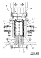
- Figures 4A and 4B are partially sectioned distinct views of the operation steps of the container profile shaping;
- Figure 5 is a perspective view of an example form of a container formed and shaped by the apparatus proposed by the present invention.
- Having regards to the enclosed figures, in particular to Figure 1, the
reference numeral 100 indicates the apparatus, proposed by the present invention and taken as a whole, for forming and shaping a container from a film material unwound from a related reel. - The
apparatus 100 includes an endless conveying line (L), having elongated support elements S, spaced apart, and operated stepwise to convey the above support elements S through subsequent work stations, which are arranged in such a way as to face the conveying line. - The work stations cooperate with the conveying line (L) to form, from a film material unwound from a relative reel, containers C having a bottom G and a shaped profile P, like e.g. in Figure 5.
- In this regard, as it has been shown in an extremely schematic way in Figure 1, the work stations include at least:
- a forming station (A) for forming a tubular element (T) from a film material unwinding from the related reel and
- for fitting the tubular element (T) onto a corresponding support element (S), which has been positioned in the meantime by the conveying line (L), dwelling in front of the forming station (A);
- a closing station (B), situated after the forming station (A) in a conveying direction of the conveying line (L) and aimed at closing the outer end of the tubular element (T) to define a bottom (G), in order to form an open container (C),
- a shaping station (D), situated downstream of the closing station (B) in the conveying direction of the conveying line (L) and having a closeable mold (E), in which the container (C) is inserted and kept, and inside which the lateral walls of the container (C) are subjected to deformation and shaping by the use of an operational fluid, which is introduced under pressure into the mold (E) by a supply system (V).
-
- The innovative characteristic of the apparatus (100), proposed by the present invention, with respect to the known apparatuses, lies in the particular conformation of the support elements (S).
- Actually, the characteristic feature of the apparatus (100) lies in the fact that each of the support elements (S) includes a rigid, tubular core (1) and a covering (2), tight proof and elastically deformable, which wraps and covers the tubular core (1) (see for example Figure 2, in which the covering (2) is shown removed from the tubular core (1), while in Figures 3 and 4A, the covering (2) is shown in its operation configuration, in which it covers the tubular core (1) to form a support element (S)).
- The tubular core (1) of the support element (S) is set in communication with the supply system (V) when the conveying line (L) moves it to the shaping station (D) and inside the mold (E).
- The tubular core (1) of the support element (S) has holes (10), made in its lateral walls for allowing the passage of the operational fluid.
- The rest configuration of the covering (2) allows it to surround and cover the tubular core (1), adhering to and mating with the lateral walls thereof.
- The covering (2) is to be wrapped by the tubular element (T) to form the open container (C) during the conveying of the support element (S), by the conveying line (L), through the forming station (A) and the closing station (B).
- When the support element (S), with the relative container (C) fitted thereon, is disposed in the shaping station (D), inside the mold (E), the covering (2) can undergo an elastic deformation, due to the introduction, by the supply system (V), of the operational fluid under pressure into the tubular core (1), and consequently, detach from the lateral walls of the tubular core (1).
- The deformation of the covering (2) caused by the fluid under pressure passing through the holes (10), made in the lateral walls of the tubular core (1), provokes a consequent deformation of the lateral walls of the container (C), fitted onto the latter.
- The lateral walls of the container (C) are pushed against the inner shaped walls (F) of the mold (E) to assume a corresponding profile (in this regard, see in particular Figure 4B).
- As a consequence of the deactivation of the supply of the fluid under pressure into the tubular core (1), by the supply system (V), the covering (2) can also, due to its elasticity, reassume its initial rest position, in which it adheres to and mates with the lateral walls of the tubular core (1) again (configuration shown in Figure 3 and Figure 4A), so as to make the support element (S) ready to resume the working cycle for forming another container (C).
- According to the embodiment shown in the enclosed figures, the tubular core (1) includes a base (11), fastened to the conveying line (L) (Figure 3), and a tubular body (12), which has an elongated shape and a section corresponding to the cross-section of the container (C) to be obtained, and which has the holes (10) made in the relative lateral walls to allow the operational fluid to pass.
- The tubular core (1) has an annular groove (13), situated between the upper portion of the base (11) and the lower portion of the tubular body (12).
- The covering (2) has the cross-section complementary to the cross-section of the tubular body (12) and it has an inner head (21), partially open, and an outer head (22), closed.
- The tubular body (12) passes through the partially open inner head (21) to allow the covering (2) to be positioned on the tubular core (1) in order to cover the latter.
- The partially open inner head (21) clutches in a rigid coupling inside the annular groove (13).
- The closed outer head (22) is aimed at adhering to the outer end of the tubular body (12) and at being fitted by the bottom (G) of the container (C), giving the latter a corresponding shape (see for example Figure 4A).
- Another characteristic feature of the proposed apparatus lies in the fact that the partially open inner head (21) of the covering (2) has a transversal first outer annular lip (23) and a second inner annular lip (24), which involve and adhere, respectively to the lower surface (14) and to the upper surface (15) of the annular groove (13) of the tubular core, defining, between the two lips, a tight proof chamber (25), whose function will be better explained and shown later on (see for example Figure 4A).
- The above mentioned base (11) of the tubular core (1) has at least one main conduit (3) extending from the relative lower face and opening into the tubular body (12).
- The main conduit (3) sets the inside of the tubular body (12) of the tubular core (1) in communication with the outside when the support element (S) is conveyed and then positioned at the forming station (A) and closing station (B), while it is connected to a delivery conduit of the pressurized fluid supply system (V), when the support element (S) is moved to the shaping station (D) inside the mold (E).
- The main conduit (3) has an additional branch conduit (31), which opens into a hole (16) made in the annular groove (13) of the tubular core (1) and which communicates with the tight proof chamber (25) defined by the outer annular lip (23) and inner annular lip (24).
- The presence of the additional branch conduit (31) allows, together with the introduction of the pressurized fluid into the tubular core (1) by the supply system (V), through the main conduit (3), to deform the tight proof chamber (25), so as to dilate its outer lateral walls, pushing them toward the inner walls of the mold (E).
- Consequently, the dilation of the outer lateral walls of the tight proof chamber (25) pushes the walls (CA) of the open end of the container (C) against the inner walls of the mold (E), thus assuring the perfect air tightness.
- As it is shown for example in Figure 3, the mold (E) includes two semi-shells (E1) and (E2), which can be tightened together to enclose the lateral walls of the container (C), whose inner walls (F) are shaped according to the desired profile to be given to the lateral walls of the container (C).
- The mold (E) includes also an upper closing element (E3), which can be lowered until it goes in abutment against the bottom (G) of the container (C) and the closed outer head (22) of the covering (2) of the support element (S).
- In the tightened configuration, the lower portions of the inner walls (F) of the two semi-shells (E1) and (E2) touch the outer lateral walls of the tight proof chamber (25), thus defining a kind of closed chamber, containing the container (C), whose profile is to be shaped.
- The dilation of the tight proof chamber (25) in the above described way, assures the perfect air-tightness of the closed chamber with respect to the outside.
- Moreover, the mold (E) includes heating means and cooling means, not shown, since of known type and not included in the scope of the present invention.
- The particular conformation of the support elements (S), together with the presence of the covering (2) covering the tubular core (1) make the proposed apparatus particularly innovative, and its use particularly advantageous with respect to the known ones.
- Actually, the covering (2), which protects the inner walls of the container (C) from the direct contact with the operational fluid, introduced under pressure into the support element (S) in the shaping station (D), allows to use an operational fluid in liquid state, contrary to the prior art apparatuses.
- In fact, the proposed apparatus (100) has a hydraulic supply system (V), situated in the shaping station (D), below the conveying line (L), and introducing, after being joined to the main conduit (3) inside the base (11) of the tubular core (1), a pressurized fluid in a liquid state, into the support element (S).
- The hydraulic supply system can introduce into the support element (S) the fluid in the liquid state, which cannot be compressed, with the pressure values considerably higher than the ones reached by the prior art apparatuses, in considerably shorter times, and without any blast risk.
- Further, after the profile (P) of the container (C) has been shaped, the restoration of the initial conditions, as a consequence of the deactivation of the hydraulic system, occurs extremely rapidly, because the flow of the liquid fluid from the inside of the support element (S) is quicker with respect to the flow of a compressed gas.
- The hydraulic supply system can have valve means for regulating the flow of the liquid fluid, situated along the system delivery conduit to be joined to the main conduit (3).
- Likewise, the main conduit (3) can have valve means (not shown), which can be opened or closed to optimize the introduction of the liquid fluid into the support element (S), and/or to adjust the flow of the liquid fluid from the support element (S).
- The possibility to reach pressure values higher than the ones reached by the prior art apparatuses allows the apparatus proposed by the present invention to form and shape a container from film materials thicker and more rigid than the plastic and/or paper materials.
- Consequently, the proposed apparatus can form and shape a container also from materials like aluminium or tin, to obtain a can or other, similar containers.
- Further, the use of a liquid fluid allows to simplify the structure of the base of a support element, which has only one main conduit (3), used for the introduction of the pressurized liquid fluid into the support element (S), as well as for simultaneous activating, by the branch conduit (31), the deformation of the tight proof chamber (25), in order to assure the air-tightness.
- However, the above reflections do not exclude the possibility of using the proposed apparatus with pneumatic supply system and thus with aeriform fluids, for shaping the container in the shaping station.
- The presence of the covering (2) allows advantageously, as it has already been pointed out previously, to avoid the direct contact between the operational fluid and the inner walls of the container, thus protecting the latter from the contaminations, which can be produced by the impurities present in the fluid.
- The proposed apparatus (100) can also include a sterilizing station (Z) (shown with broken line in Figure 1), which is situated between the shaping station (D) and the forming station (A) and through which the support elements (S) pass, moved by the conveying line (L), after having been freed from the relative shaped container.
- This way, the covering (2) of the support element (S) is subjected to a sterilizing action before being conveyed to the forming station (A) and being fitted again onto a relative tubular element (T).
- Summing up, the apparatus proposed by the present invention, advantageously with respect to the known apparatuses, allows:
- forming and shaping a container from film materials, either plastic or paper, or materials thicker and more rigid, such as aluminium or tin;
- keeping the inner walls of the container being formed and shaped protected from any contamination;
- speeding up the shaping operations in the shaping station, increasing considerably the production rate.
Claims (11)
- Apparatus for forming and shaping a container from a film material unwound from a related reel, including:an endless conveying line (L) provided with elongated support elements (S), spaced apart, and operated to convey each of the support elements (S) to subsequent work stations arranged so as to face the line (L), said stations including a tubular element (T) forming station (A), in which a tubular element (T) is formed and cut from said material and is fitted onto a corresponding support element (S), a closing station (B), in which the outer end of said tubular element (T) is closed to define a bottom (G) to form an open container (C), and a shaping station (D), having a closeable mold (E), within which the container (C) is inserted and contained, and within which the lateral walls of the container (C) are shaped by using an operational pressurized fluid introduced into the mold (E) by a supply system (V), associated to the shaping station (D), with said apparatus (100) characterized in that each of said support elements (S) includes:a tubular rigid core (1), set in communication with said supply system (V) when it is located in said shaping station (D), and having holes (10) made in its lateral walls for the passage of said operational fluid; andan elastically deformable tight proof covering (2) for surrounding and covering, while in rest condition, the tubular core (1), adhering to and mating with its lateral walls, said covering (2) being fitted by said tubular element (T) to form said open container (C) and undergoing an elastic deformation when said container (C) is located in the shaping station (D) and inside the mold (E), due to introduction, by the supply system (V), of the pressurized operational fluid into the tubular core (1), so as to detach from the tubular core (1) and to accompany the lateral walls of said container (C), making them adhere and mate with the inner shaped walls (F) of said mold (E), in order to assume a corresponding profile, said covering (2) reassuming also, as a consequence of the deactivation of the supply system, its initial rest position, in which it adheres to and mates with the lateral walls of the tubular core (1) again.
- Apparatus, as claimed in claim 1, characterized in that said tubular core (1) includes a base (11), fastened to said conveying line (L), and a tubular body (12), which has an elongated shape and a cross-section corresponding to the cross-section of the container (C) to be obtained, and which has the holes (10) made in the relative lateral walls to allow the operational fluid to pass, said tubular core (1) having also an annular groove (13), situated between the upper portion of the base (11) and the lower portion of the tubular body (12), and in that said covering (2) has the cross-section complementary to the cross-section of said tubular body (12) and it has an inner head (21), partially open, through which said tubular body (12) passes to allow the covering (2) to be positioned on the tubular core (1) in order to cover the latter, said partially open inner head (21) introducing in a stable connection inside said annular groove (13) and being fitted by the open end of said container (C), said covering (2) having also a closed outer head (22) adhering to the outer end of said tubular body (12) and being fitted by the bottom (G) of the container (C), giving the latter a corresponding shape.
- Apparatus, as claimed in claim 2, characterized in that said partially open inner head (21) of said covering (2) includes a transversal first outer annular lip (23) and a second inner annular lip (24), which involve and adhere, respectively to the lower surface (14) and to the upper surface (15) of said annular groove (13) of the tubular core (1), defining, between the two lips, a tight proof chamber (25).
- Apparatus, as claimed in claim 2 or 3, characterized in that the base (11) of said tubular core (1) has at least one main conduit (3), which sets the inside of the tubular body (12) of the tubular core (1) in communication with the outside during the conveying of the support element (S) to the tubular element (T) forming station (A) and to the closing station (B), where the outer end of said tubular element (T) is closed to define a bottom (G) to form an open container (C), while it is connected to the pressurized fluid supply system (V), when the support element (S) is located, by said conveying line (L), in the shaping station (D) and within the mold (E).
- Apparatus, as claimed in claim 3 or 4, characterized in that said main conduit (3) has an additional branch conduit (31), which opens into a hole (16) made in the annular groove (13) of said tubular core (1) and which communicates with said tight proof chamber (25), said pressurized operational fluid passing through said additional branch conduit (31) after being introduced in said main conduit (3) by said supply system (V) to deform said tight proof chamber (25), so as to dilate its outer lateral walls and to move the lateral walls of the open end (CA) of the container (C) against the inner walls of the mold (E), to assure its tightness.
- Apparatus, as claimed in any claim from 1 to 5, characterized in that said supply system (V), associated to said shaping station (D), includes a hydraulic supply system and in that the operational fluid is a fluid in a liquid state.
- Apparatus, as claimed in any claim from 1 to 5, characterized in that said supply system (V), associated to said shaping station (D) includes a pneumatic supply system and in that the operational fluid is a fluid in an aeriform state.
- Apparatus, as claimed in any claim from 1 to 5, characterized in that said mold (E) of said shaping station (D) includes two semi-shells (E1) and (E2), which can be tightened together to enclose the lateral walls of said open container (C), whose inner walls (F) are shaped according to the desired profile to be given to the lateral walls of the container (C), said mold (E) including also an upper closing element (E3), which can be lowered.
- Apparatus, as claimed in claim 8, characterized in that said mold includes heating means and cooling means.
- Apparatus, as claimed in any claim from 1 to 5, characterized in that it includes a sterilizing station (Z), situated between the shaping station (D) and the forming station (A) and through which the support elements (S) pass, moved by the conveying line (L), so that the covering (2) is sterilized.
- Apparatus for forming and shaping a container from a film material unwound from a related reel, including:an endless conveying line (L) having elongated support elements (S), spaced apart, and operated to convey each of the support elements (S) to subsequent work stations arranged in a way as to face the line (L), said stations including a tubular element (T) forming station (A), in which a tubular element (T) is formed and cut from said material and is fitted onto a corresponding support element (S), a closing station (B), in which the outer end of said tubular element (T) is closed to define a bottom (G) to form an open container (C), and a shaping station (D), having a closeable mold (E), within which the container (C) is inserted and contained, and within which the lateral walls of the container (C) are shaped by the use of an operational pressurized fluid introduced into the mold (E) by a supply system (V), associated to the shaping station (D), with said apparatus (100) characterized in that said supply system (V) includes a hydraulic supply system and said operational fluid is in liquid state, and in that each of said support elements (S) includes:a tubular rigid core (1), set in communication with said supply system (V), when it is located in said shaping station (D), and having holes (10) made in its lateral walls for the passage of said operational fluid; anda tight proof covering (2), elastically deformable, which surround and covers, while in rest condition, the tubular core (1), adhering to and mating with its lateral walls, said covering (2) being fitted by said tubular element (T) to form said open container (C) and when said container (C) is located in the shaping station (D), inside the mold (E), undergoing an elastic deformation, due to the introduction, by the supply system (V), of the pressurized operational fluid into the tubular core (1), so as to detach from the tubular core (1) and to push the lateral walls of said container (C), making them adhere and mate with the inner shaped walls (F) of said mold (E), in order to assume a corresponding profile, said covering (2) reassuming also, as a consequence of the deactivation of the supply system, its initial rest position, in which it adheres to and mates with the lateral walls of the tubular core (1) again.
Applications Claiming Priority (2)
| Application Number | Priority Date | Filing Date | Title |
|---|---|---|---|
| IT000235A ITBO20040235A1 (en) | 2004-04-21 | 2004-04-21 | EQUIPMENT FOR THE FORMATION OF A CONTAINER AND THE SHAPING OF ITS PROFILE, STARTING FROM A FILM MATERIAL |
| ITBO20040235 | 2004-04-21 |
Publications (3)
| Publication Number | Publication Date |
|---|---|
| EP1588835A2 true EP1588835A2 (en) | 2005-10-26 |
| EP1588835A3 EP1588835A3 (en) | 2007-07-11 |
| EP1588835B1 EP1588835B1 (en) | 2009-12-23 |
Family
ID=34935459
Family Applications (1)
| Application Number | Title | Priority Date | Filing Date |
|---|---|---|---|
| EP05008641A Not-in-force EP1588835B1 (en) | 2004-04-21 | 2005-04-20 | Apparatus for forming and shaping a container from a film material |
Country Status (4)
| Country | Link |
|---|---|
| EP (1) | EP1588835B1 (en) |
| AT (1) | ATE452750T1 (en) |
| DE (1) | DE602005018409D1 (en) |
| IT (1) | ITBO20040235A1 (en) |
Cited By (2)
| Publication number | Priority date | Publication date | Assignee | Title |
|---|---|---|---|---|
| EP1974898A2 (en) * | 2007-03-29 | 2008-10-01 | Giorgio Trani | Method for forming three-dimensional containers of extensible paper material. |
| CN110997277A (en) * | 2017-07-21 | 2020-04-10 | 斯蒂利亚诺斯·埃莱夫特里乌 | Machine for manufacturing plastic articles by blow moulding |
Citations (5)
| Publication number | Priority date | Publication date | Assignee | Title |
|---|---|---|---|---|
| GB898387A (en) * | 1959-05-05 | 1962-06-06 | Georges Duffau | Collapsible tube and apparatus for producing said tube |
| US4009982A (en) * | 1974-02-11 | 1977-03-01 | Universal Plastic Pipe Bending Corporation | Mechanism for forming an enlarged coupling on the ends of plastic pipe |
| DE2614576A1 (en) * | 1976-04-05 | 1977-10-13 | Farrell Plastic Mach | Blow mould set - comprises core rod with inflatable balloon and perforated shell mould in air chamber |
| WO2004054783A1 (en) * | 2002-12-18 | 2004-07-01 | Carcoustics Tech Center Gmbh | Device and method for moulding semi-finished pieces made from open-cell material |
| WO2004098862A2 (en) * | 2003-05-07 | 2004-11-18 | Newtec International Group (Sa) | System and method for blowing hollow plastic bodies, minimising high-pressure air consumption |
-
2004
- 2004-04-21 IT IT000235A patent/ITBO20040235A1/en unknown
-
2005
- 2005-04-20 EP EP05008641A patent/EP1588835B1/en not_active Not-in-force
- 2005-04-20 DE DE602005018409T patent/DE602005018409D1/en not_active Expired - Fee Related
- 2005-04-20 AT AT05008641T patent/ATE452750T1/en not_active IP Right Cessation
Patent Citations (5)
| Publication number | Priority date | Publication date | Assignee | Title |
|---|---|---|---|---|
| GB898387A (en) * | 1959-05-05 | 1962-06-06 | Georges Duffau | Collapsible tube and apparatus for producing said tube |
| US4009982A (en) * | 1974-02-11 | 1977-03-01 | Universal Plastic Pipe Bending Corporation | Mechanism for forming an enlarged coupling on the ends of plastic pipe |
| DE2614576A1 (en) * | 1976-04-05 | 1977-10-13 | Farrell Plastic Mach | Blow mould set - comprises core rod with inflatable balloon and perforated shell mould in air chamber |
| WO2004054783A1 (en) * | 2002-12-18 | 2004-07-01 | Carcoustics Tech Center Gmbh | Device and method for moulding semi-finished pieces made from open-cell material |
| WO2004098862A2 (en) * | 2003-05-07 | 2004-11-18 | Newtec International Group (Sa) | System and method for blowing hollow plastic bodies, minimising high-pressure air consumption |
Cited By (4)
| Publication number | Priority date | Publication date | Assignee | Title |
|---|---|---|---|---|
| EP1974898A2 (en) * | 2007-03-29 | 2008-10-01 | Giorgio Trani | Method for forming three-dimensional containers of extensible paper material. |
| EP1974898A3 (en) * | 2007-03-29 | 2014-03-19 | Giorgio Trani | Method for forming three-dimensional containers of extensible paper material. |
| CN110997277A (en) * | 2017-07-21 | 2020-04-10 | 斯蒂利亚诺斯·埃莱夫特里乌 | Machine for manufacturing plastic articles by blow moulding |
| US11426918B2 (en) | 2017-07-21 | 2022-08-30 | Stylianos ELEFTHERIOU | Machine for manufacturing plastic items by blow moulding |
Also Published As
| Publication number | Publication date |
|---|---|
| ITBO20040235A1 (en) | 2004-07-21 |
| DE602005018409D1 (en) | 2010-02-04 |
| EP1588835B1 (en) | 2009-12-23 |
| EP1588835A3 (en) | 2007-07-11 |
| ATE452750T1 (en) | 2010-01-15 |
Similar Documents
| Publication | Publication Date | Title |
|---|---|---|
| US4543770A (en) | Apparatus for producing and charging containers in a sterile atmosphere | |
| KR101980130B1 (en) | Method and device for forming wrapped food item | |
| ITMO20080085A1 (en) | APPARATUS FOR FORMING ASEPTIC CONTAINERS | |
| EP2419668B1 (en) | Apparatus for transferring incoherent or liquid material | |
| US8020590B2 (en) | Nozzle for filling a container with at least two viscous materials | |
| US7827770B2 (en) | Method for the operation of a package emptying station | |
| US9289939B2 (en) | Apparatus and method of shaping plastics material pre-forms with separate flow paths for blowing air and control air | |
| EP1588835A2 (en) | Apparatus for forming and shaping a container from a film material | |
| JPH0398803A (en) | Device for filling container | |
| US3175591A (en) | Sanitary dispensing nozzles for filling machines | |
| JPH05270525A (en) | Heat seal station | |
| US4574720A (en) | Method and apparatus for filling valved bags | |
| RU2716123C1 (en) | Device for mixing components of explosive composition and molding articles therefrom | |
| CN109231112B (en) | Filling unit and filling method for filling an article with a pourable product | |
| JPH05245533A (en) | Extruding press assembly | |
| KR20190127815A (en) | Method and apparatus for making double bags | |
| JPH04229225A (en) | Molding of hollow part using thermally plastic web | |
| CN103167858B (en) | Device and installation for joining at least two medicine capsules by adhesive bonding | |
| CN102672945B (en) | Blow moulding device with sterile area and sterile blown air supply | |
| JP3681599B2 (en) | Powder discharging coupling device | |
| CN215047048U (en) | Finished product vanning is with leak protection material pipe tobacco guide device | |
| CZ2004999A3 (en) | Method for processing wrongly filled beverage containers and apparatus for making the same | |
| JPH0237681Y2 (en) | ||
| JP2022016901A (en) | Filling valve device and filling system | |
| JP2012055169A (en) | Apparatus and method for forming ring-shaped food |
Legal Events
| Date | Code | Title | Description |
|---|---|---|---|
| PUAI | Public reference made under article 153(3) epc to a published international application that has entered the european phase |
Free format text: ORIGINAL CODE: 0009012 |
|
| AK | Designated contracting states |
Kind code of ref document: A2 Designated state(s): AT BE BG CH CY CZ DE DK EE ES FI FR GB GR HU IE IS IT LI LT LU MC NL PL PT RO SE SI SK TR |
|
| AX | Request for extension of the european patent |
Extension state: AL BA HR LV MK YU |
|
| PUAL | Search report despatched |
Free format text: ORIGINAL CODE: 0009013 |
|
| AK | Designated contracting states |
Kind code of ref document: A3 Designated state(s): AT BE BG CH CY CZ DE DK EE ES FI FR GB GR HU IE IS IT LI LT LU MC NL PL PT RO SE SI SK TR |
|
| AX | Request for extension of the european patent |
Extension state: AL BA HR LV MK YU |
|
| RIC1 | Information provided on ipc code assigned before grant |
Ipc: B31B 37/00 20060101ALI20070606BHEP Ipc: B29C 51/28 20060101ALI20070606BHEP Ipc: B31B 43/00 20060101AFI20050818BHEP Ipc: B29C 49/44 20060101ALI20070606BHEP |
|
| 17P | Request for examination filed |
Effective date: 20080108 |
|
| 17Q | First examination report despatched |
Effective date: 20080204 |
|
| AKX | Designation fees paid |
Designated state(s): AT BE BG CH CY CZ DE DK EE ES FI FR GB GR HU IE IS IT LI LT LU MC NL PL PT RO SE SI SK TR |
|
| GRAP | Despatch of communication of intention to grant a patent |
Free format text: ORIGINAL CODE: EPIDOSNIGR1 |
|
| GRAS | Grant fee paid |
Free format text: ORIGINAL CODE: EPIDOSNIGR3 |
|
| GRAA | (expected) grant |
Free format text: ORIGINAL CODE: 0009210 |
|
| AK | Designated contracting states |
Kind code of ref document: B1 Designated state(s): AT BE BG CH CY CZ DE DK EE ES FI FR GB GR HU IE IS IT LI LT LU MC NL PL PT RO SE SI SK TR |
|
| REG | Reference to a national code |
Ref country code: GB Ref legal event code: FG4D |
|
| REG | Reference to a national code |
Ref country code: CH Ref legal event code: EP |
|
| REG | Reference to a national code |
Ref country code: IE Ref legal event code: FG4D |
|
| REF | Corresponds to: |
Ref document number: 602005018409 Country of ref document: DE Date of ref document: 20100204 Kind code of ref document: P |
|
| REG | Reference to a national code |
Ref country code: NL Ref legal event code: VDEP Effective date: 20091223 |
|
| PG25 | Lapsed in a contracting state [announced via postgrant information from national office to epo] |
Ref country code: SE Free format text: LAPSE BECAUSE OF FAILURE TO SUBMIT A TRANSLATION OF THE DESCRIPTION OR TO PAY THE FEE WITHIN THE PRESCRIBED TIME-LIMIT Effective date: 20091223 Ref country code: LT Free format text: LAPSE BECAUSE OF FAILURE TO SUBMIT A TRANSLATION OF THE DESCRIPTION OR TO PAY THE FEE WITHIN THE PRESCRIBED TIME-LIMIT Effective date: 20091223 Ref country code: FI Free format text: LAPSE BECAUSE OF FAILURE TO SUBMIT A TRANSLATION OF THE DESCRIPTION OR TO PAY THE FEE WITHIN THE PRESCRIBED TIME-LIMIT Effective date: 20091223 |
|
| LTIE | Lt: invalidation of european patent or patent extension |
Effective date: 20091223 |
|
| PG25 | Lapsed in a contracting state [announced via postgrant information from national office to epo] |
Ref country code: PL Free format text: LAPSE BECAUSE OF FAILURE TO SUBMIT A TRANSLATION OF THE DESCRIPTION OR TO PAY THE FEE WITHIN THE PRESCRIBED TIME-LIMIT Effective date: 20091223 Ref country code: SI Free format text: LAPSE BECAUSE OF FAILURE TO SUBMIT A TRANSLATION OF THE DESCRIPTION OR TO PAY THE FEE WITHIN THE PRESCRIBED TIME-LIMIT Effective date: 20091223 |
|
| PG25 | Lapsed in a contracting state [announced via postgrant information from national office to epo] |
Ref country code: AT Free format text: LAPSE BECAUSE OF FAILURE TO SUBMIT A TRANSLATION OF THE DESCRIPTION OR TO PAY THE FEE WITHIN THE PRESCRIBED TIME-LIMIT Effective date: 20091223 |
|
| PG25 | Lapsed in a contracting state [announced via postgrant information from national office to epo] |
Ref country code: RO Free format text: LAPSE BECAUSE OF FAILURE TO SUBMIT A TRANSLATION OF THE DESCRIPTION OR TO PAY THE FEE WITHIN THE PRESCRIBED TIME-LIMIT Effective date: 20091223 Ref country code: NL Free format text: LAPSE BECAUSE OF FAILURE TO SUBMIT A TRANSLATION OF THE DESCRIPTION OR TO PAY THE FEE WITHIN THE PRESCRIBED TIME-LIMIT Effective date: 20091223 Ref country code: ES Free format text: LAPSE BECAUSE OF FAILURE TO SUBMIT A TRANSLATION OF THE DESCRIPTION OR TO PAY THE FEE WITHIN THE PRESCRIBED TIME-LIMIT Effective date: 20100403 Ref country code: PT Free format text: LAPSE BECAUSE OF FAILURE TO SUBMIT A TRANSLATION OF THE DESCRIPTION OR TO PAY THE FEE WITHIN THE PRESCRIBED TIME-LIMIT Effective date: 20100423 Ref country code: IS Free format text: LAPSE BECAUSE OF FAILURE TO SUBMIT A TRANSLATION OF THE DESCRIPTION OR TO PAY THE FEE WITHIN THE PRESCRIBED TIME-LIMIT Effective date: 20100423 Ref country code: EE Free format text: LAPSE BECAUSE OF FAILURE TO SUBMIT A TRANSLATION OF THE DESCRIPTION OR TO PAY THE FEE WITHIN THE PRESCRIBED TIME-LIMIT Effective date: 20091223 Ref country code: BG Free format text: LAPSE BECAUSE OF FAILURE TO SUBMIT A TRANSLATION OF THE DESCRIPTION OR TO PAY THE FEE WITHIN THE PRESCRIBED TIME-LIMIT Effective date: 20100323 |
|
| PG25 | Lapsed in a contracting state [announced via postgrant information from national office to epo] |
Ref country code: SK Free format text: LAPSE BECAUSE OF FAILURE TO SUBMIT A TRANSLATION OF THE DESCRIPTION OR TO PAY THE FEE WITHIN THE PRESCRIBED TIME-LIMIT Effective date: 20091223 Ref country code: BE Free format text: LAPSE BECAUSE OF FAILURE TO SUBMIT A TRANSLATION OF THE DESCRIPTION OR TO PAY THE FEE WITHIN THE PRESCRIBED TIME-LIMIT Effective date: 20091223 Ref country code: CZ Free format text: LAPSE BECAUSE OF FAILURE TO SUBMIT A TRANSLATION OF THE DESCRIPTION OR TO PAY THE FEE WITHIN THE PRESCRIBED TIME-LIMIT Effective date: 20091223 |
|
| PG25 | Lapsed in a contracting state [announced via postgrant information from national office to epo] |
Ref country code: GR Free format text: LAPSE BECAUSE OF FAILURE TO SUBMIT A TRANSLATION OF THE DESCRIPTION OR TO PAY THE FEE WITHIN THE PRESCRIBED TIME-LIMIT Effective date: 20100324 Ref country code: CY Free format text: LAPSE BECAUSE OF FAILURE TO SUBMIT A TRANSLATION OF THE DESCRIPTION OR TO PAY THE FEE WITHIN THE PRESCRIBED TIME-LIMIT Effective date: 20091223 |
|
| PLBE | No opposition filed within time limit |
Free format text: ORIGINAL CODE: 0009261 |
|
| STAA | Information on the status of an ep patent application or granted ep patent |
Free format text: STATUS: NO OPPOSITION FILED WITHIN TIME LIMIT |
|
| PG25 | Lapsed in a contracting state [announced via postgrant information from national office to epo] |
Ref country code: MC Free format text: LAPSE BECAUSE OF NON-PAYMENT OF DUE FEES Effective date: 20100430 |
|
| REG | Reference to a national code |
Ref country code: CH Ref legal event code: PL |
|
| 26N | No opposition filed |
Effective date: 20100924 |
|
| PG25 | Lapsed in a contracting state [announced via postgrant information from national office to epo] |
Ref country code: DK Free format text: LAPSE BECAUSE OF FAILURE TO SUBMIT A TRANSLATION OF THE DESCRIPTION OR TO PAY THE FEE WITHIN THE PRESCRIBED TIME-LIMIT Effective date: 20091223 Ref country code: IE Free format text: LAPSE BECAUSE OF NON-PAYMENT OF DUE FEES Effective date: 20100420 |
|
| PG25 | Lapsed in a contracting state [announced via postgrant information from national office to epo] |
Ref country code: CH Free format text: LAPSE BECAUSE OF NON-PAYMENT OF DUE FEES Effective date: 20100430 Ref country code: DE Free format text: LAPSE BECAUSE OF NON-PAYMENT OF DUE FEES Effective date: 20101103 Ref country code: LI Free format text: LAPSE BECAUSE OF NON-PAYMENT OF DUE FEES Effective date: 20100430 |
|
| PG25 | Lapsed in a contracting state [announced via postgrant information from national office to epo] |
Ref country code: HU Free format text: LAPSE BECAUSE OF FAILURE TO SUBMIT A TRANSLATION OF THE DESCRIPTION OR TO PAY THE FEE WITHIN THE PRESCRIBED TIME-LIMIT Effective date: 20100624 Ref country code: LU Free format text: LAPSE BECAUSE OF NON-PAYMENT OF DUE FEES Effective date: 20100420 |
|
| PG25 | Lapsed in a contracting state [announced via postgrant information from national office to epo] |
Ref country code: TR Free format text: LAPSE BECAUSE OF FAILURE TO SUBMIT A TRANSLATION OF THE DESCRIPTION OR TO PAY THE FEE WITHIN THE PRESCRIBED TIME-LIMIT Effective date: 20091223 |
|
| PGFP | Annual fee paid to national office [announced via postgrant information from national office to epo] |
Ref country code: GB Payment date: 20140424 Year of fee payment: 10 |
|
| PGFP | Annual fee paid to national office [announced via postgrant information from national office to epo] |
Ref country code: FR Payment date: 20140424 Year of fee payment: 10 Ref country code: IT Payment date: 20140429 Year of fee payment: 10 |
|
| GBPC | Gb: european patent ceased through non-payment of renewal fee |
Effective date: 20150420 |
|
| PG25 | Lapsed in a contracting state [announced via postgrant information from national office to epo] |
Ref country code: GB Free format text: LAPSE BECAUSE OF NON-PAYMENT OF DUE FEES Effective date: 20150420 Ref country code: IT Free format text: LAPSE BECAUSE OF NON-PAYMENT OF DUE FEES Effective date: 20150420 |
|
| REG | Reference to a national code |
Ref country code: FR Ref legal event code: ST Effective date: 20151231 |
|
| PG25 | Lapsed in a contracting state [announced via postgrant information from national office to epo] |
Ref country code: FR Free format text: LAPSE BECAUSE OF NON-PAYMENT OF DUE FEES Effective date: 20150430 |