EP1588315B1 - Dekorrelation von signalen - Google Patents
Dekorrelation von signalen Download PDFInfo
- Publication number
- EP1588315B1 EP1588315B1 EP03777016.1A EP03777016A EP1588315B1 EP 1588315 B1 EP1588315 B1 EP 1588315B1 EP 03777016 A EP03777016 A EP 03777016A EP 1588315 B1 EP1588315 B1 EP 1588315B1
- Authority
- EP
- European Patent Office
- Prior art keywords
- signals
- delay
- matrix
- input signals
- decorrelation
- Prior art date
- Legal status (The legal status is an assumption and is not a legal conclusion. Google has not performed a legal analysis and makes no representation as to the accuracy of the status listed.)
- Expired - Lifetime
Links
Images


Classifications
-
- G—PHYSICS
- G06—COMPUTING OR CALCULATING; COUNTING
- G06F—ELECTRIC DIGITAL DATA PROCESSING
- G06F18/00—Pattern recognition
- G06F18/20—Analysing
- G06F18/21—Design or setup of recognition systems or techniques; Extraction of features in feature space; Blind source separation
- G06F18/213—Feature extraction, e.g. by transforming the feature space; Summarisation; Mappings, e.g. subspace methods
- G06F18/2134—Feature extraction, e.g. by transforming the feature space; Summarisation; Mappings, e.g. subspace methods based on separation criteria, e.g. independent component analysis
Definitions
- This invention relates to decorrelation of signals; more particularly it relates to decorrelation of signals that have undergone convolutive mixing, and to a method, an apparatus and a computer program for implementing decorrelation.
- Decorrelation is known: it is a form of signal processing implemented by software running on a computer system and accepting data from sensors after conversion from analogue to digital form.
- Stationarity means that signals and channels in which they mix do not change over a time interval during which mixed signals are sampled.
- Linearity means that mixtures of signals received by sensors are linear combinations of these signals. More complicated combinations featuring signal products and squares and higher order powers of signals are not considered.
- the aim of decorrelation is to remove similarities between input signals, thereby eliminating redundancies. In some circumstances this may lead to recovering the signals as they were prior to mixing, but more usually it is used as a pre-processing step in an unmixing algorithm, or as part of another algorithm such as a data compression algorithm.
- a common usage is to separate the signals which carry meaningful data from those that arise due entirely to noise in the environment and in a receiver system which detects the signals: such separation may be an end in itself, or it may be used as part of a data compression scheme.
- Decorrelation is a process of removing correlations or similarities between signal pairs in a set of signals: correlation of a pair of signals is itself defined mathematically as an integral of the signal pair's product over time. It is important that as little information as possible (preferably none) is destroyed in decorrelation process, as would occur for example if decorrelation led to one of the signals being zeroed. Use of energy preserving transforms for decorrelation avoids information being destroyed and leads to output signals with other useful properties.
- Algorithms for decorrelating signals that have been instantaneously mixed are known: they may use either transforms that are energy preserving or those that are not.
- an algorithm for imposing strong decorrelation by an energy preserving filter employs a paraunitary matrix.
- a paraunitary matrix is one which gives the identity matrix when multiplied by its paraconjugate matrix - a polynomial equivalent of a Hermitian conjugate matrix.
- a possible approach for the strong decorrelation problem is therefore to search for a paraunitary matrix that maximises a measure of the wide sense decorrelation.
- Spectral majorisation is useful if the algorithm is to be used for data compression or for separating signal and noise subspaces.
- Gradient descent methods which aim to adjust all parameters of a paraunitary matrix or an unmixing filter simultaneously: these methods have another difficulty, i.e. they have parameters linked to any useful measure of independence in a very complex way which does not factorise easily. This means adjusting all parameters at once: it leads to very slow algorithm convergence, which is why none of the algorithms previously mentioned use gradient descent. Gradient descent tends to be avoided in the prior art due to problems with speed and accuracy of convergence.
- the present invention provides a computer implemented method of strong decorrelation of signals obtained from sensors and which are input signals, characterised in that it includes the steps of:-
- the invention provides a technique for wide sense decorrelation of signals which have been convolutively mixed, even if mixed using unknown filters. It is suitable, for example, for signals which have undergone multipath reflection, or acoustic signals in a reverberant environment. It is believed that the method of the invention is more reliable and requires less calculation than any alternative currently known.
- decorrelation is carried out using an energy preserving transform, and examples of the invention may (not necessarily but if required) impose spectral majorisation on the signals as well as imposing wide sense decorrelation.
- the method of the invention may determine in step a) delay and rotation parameters which characterise a single elementary paraunitary matrix. It may include producing a paraunitary matrix by cumulatively multiplying successive elementary paraunitary matrices produced by iterating step a).
- the range of signal delay parameters may be a set of discrete delay vectors, and the delay and rotation parameters may be determined by generating a respective version of the input signals delayed by each delay vector in the set, and for each version finding rotation parameters which at least approach producing maximisation of the output signals' strong decorrelation.
- the rotation parameters which at least approach producing maximisation of the output signals' strong decorrelation may be determined using an algorithm for instantaneous decorrelation.
- the at least one elementary paraunitary matrix may implement at least one leading delay, rotation and terminal delay.
- the method may involve n input signals where n is an integer greater than 2, the range of signal delay parameters being a set of n-element delay vectors and the range of signal rotation parameters being a set of n(n-1)/2 angle parameters.
- Step a) may comprise determining delay and rotation parameters which implement at least one elementary paraunitary matrix providing for rotation of a pair of input signals and relative delay of the or as the case may be each other input signal.
- the n input signals may be associated with respective channels, step a) having n(n - 1)/2 successive stages each associated with at least one respective elementary paraunitary matrix and each providing for rotation of signals associated with a respective pair of channels and provision of relative delay associated with the or as the case may be each other channel, the first stage being arranged to process the input signals and the or as the case may be each subsequent stage being arranged to receive signals processed in the respective preceding stage.
- the method of the invention may involve a set of n input signals where n is an integer greater than 2, characterised in that it comprises:
- the present invention provides computer apparatus for strong decorrelation of signals, the apparatus being programmed for reception of input signals obtained from sensors, characterised in that the apparatus is also programmed:-
- the present invention provides a computer programme for implementing strong decorrelation of signals obtained from sensors and input to computer apparatus, characterised in that it has instructions for controlling computer apparatus:- d)
- the apparatus and computer programme aspects of the invention may include features equivalent to those mentioned above in connection with the method of the invention.
- the present invention is arrived at by modifying and extending the prior art of both instantaneously decorrelating signals and of strongly decorrelating signals: this prior art will first be discussed in more detail to enable the invention to be better understood.
- a product x 1 x 2 represents the signal obtained by multiplying each sample of a signal x 1 by a respective sample of a signal x 2 having the same sample time: this defines pointwise decorrelation of a pair of signals.
- Equation (1) can be estimated from sampled signals to determine whether or not Equation (1) holds for sampled signals. If Equation (1) holds for all signal pairs then the signals are referred to as being decorrelated.
- loudspeaker outputs (original signals) reaching the two receivers at time (t) are represented by s 1 ( t ) and s 2 ( t ): t is in units of an interval between successive digital signal samples (clock cycles), and has integer values 1, 2 etc.
- the path from each loudspeaker to each receiver and the receiver's reception characteristics give rise to a constant channel modulation.
- First and second loudspeaker signals at time (t) are represented by x 1 ( t ) and x 2 ( t ).
- Each receiver signal is the sum of two loudspeaker signals, each multiplied by a respective coefficient.
- H is referred to as the mixing matrix because it has matrix elements (coefficients) that operate on the loudspeaker signals and mix them to form the received signals.
- the sizes of s , x , and H will increase if more than two signals or more than two sensors are involved.
- algorithms for solving the instantaneous decorrelation problem produced by Equation (3) exist in the prior art.
- E ( x ) is the expectation of x , that is the mean of x over time and the superscript index H means a Hermitian conjugate.
- Equation (4) E( x ) is subtracted from x , which is the first step in all processing that follows.
- D the new correlation matrix
- the loudspeaker signal consists of a series of values indexed by the respective times t at which they were obtained and denoted by s ( t ).
- the loudspeaker signal passes through a channel and is received by the receiver that detects another series of values, x ( t ).
- the link between s ( t ) and x ( t ) may not be a simple multiplication as in instantaneous mixing. Instead x ( t ) may consist of a linear sum of several of earlier values of s ( t ).
- z -1 is referred to as a delay operator as mentioned above.
- the z-transform of a signal expressed as a time series of sample values is a polynomial in z -1 .
- its polynomial coefficients enable recovery of the original signal.
- the convolution of s by h as shown in Equation (6) becomes a multiplication of two polynomials.
- s(z) is a 2 by 1 coefficient vector formed from z-transforms of loudspeaker outputs.
- H ( z ) is a 2 by 2 coefficient polynomial mixing matrix and
- x ( z ) is the 2 by 1 vector formed from z-transforms of received signals.
- H (z) is called a polynomial mixing matrix because it represents mixing of signals: its coefficients are polynomials in z -1 . It may also be considered to be a polynomial in z -1 with coefficients which are matrices. It is found one coefficient at a time by taking z-transforms of individual loudspeaker/receiver channels. For future convenience, the order and degree of a polynomial matrix will now be defined. The order of a polynomial matrix is the greatest power to which z -1 is raised in the matrix. The degree of a polynomial matrix is the smallest number of delays necessary to implement it as a filter. It is always at least the same size as the order but may be greater.
- the instantaneous decorrelation problem only deals with removing correlation between the signals with no time delays applied to them.
- the measure of decorrelation has to operate across time delays. That is, to be strongly decorrelated, the correlation between two signals has to be zero when any time delay is applied to one of the signals.
- ⁇ d ⁇ ( ⁇ -2,-1,0,1,2, ⁇ ) means all values of delay d (in units of a time interval between successive signal samples) in the set of all positive and negative whole numbers
- Equation (12) introduces the concept of a paraconjugate x ⁇ ( z ) of a polynomial matrix x ( z ) denoted by a tilde above the matrix symbol x ⁇ . It means combined operations of transposition and conjugation (as in the Hermitian operator) and the substitution of 1/ z * for z .
- Paraconjugation is an extension of the Hermitian operator to polynomial matrices.
- the unit polynomial is the polynomial that has zero coefficients for all powers of z -1 except for z 0 which has unity as its coefficient.
- a multichannel lattice filter see e.g. S. Haykin, " Adaptive Filter Theory ", Prentice Hall, 1991, imposes strong decorrelation while ensuring that the diagonal terms of the polynomial correlation matrix are the same by forcing them all to be the unit polynomial. This whitens the signals.
- Equation (12) The polynomial correlation matrix of the signals x ( z ) is given by Equation (12) above.
- a multichannel lattice filter transforms these to obtain a matrix of strongly decorrelated and whitened signals x '(z).
- R '( z ) the identity polynomial matrix I , symbolically:-
- this method imposes the whitening condition upon the signals means that it carries out more calculation than is necessary and has not necessarily used an energy preserving transform. It can also lead to difficulties when original signals driving the mixing were not white, or when mixing nulls some of their frequency components, as it whitens the outputs and thus amplifies the noise in those frequencies that were nulled.
- Paraunitary matrices are energy preserving and, more strongly, are energy preserving at all frequencies. This means that if decorrelation is achieved by the use of paraunitary matrices, the problems of whitening mentioned above are avoided.
- the Vaidyanathan reference discloses parameterisation of the space of all paraunitary matrices. This gives a stage-by-stage decomposition of a paraunitary matrix in z -1 .
- the parameterisation is illustrated in Figure 1 for a two-channel case. It comprises a series of N+1 rotation blocks Q 0 , Q 1 , ... Q N , adjacent pairs of these blocks being separated by individual delay blocks ⁇ (z) which are all alike.
- Upper and lower signal channels 20 and 22 pass through all the blocks.
- Amplifiers 24 indicate channel input signal scaling factors ⁇ , of which the upper channel factor is positive and the lower channel factor is positive or negative as indicated by "+-" before " ⁇ ".
- Each of the rotation blocks Q 0 to Q N implements a respective 2 by 2 unitary matrix which itself implements a Givens rotation (see US Pat No 4,727,503 ): a Givens rotation is a rotation parameterised by a single rotation angle ⁇ .
- a Givens rotation is a rotation parameterised by a single rotation angle ⁇ .
- a signal in the lower channel 22 is multiplied by Givens rotation parameters s 0 and c 0 ;
- a signal in the upper channel 20 is multiplied by Givens rotation parameters -s 0 and c 0 ;
- s 0 and c 0 are respectively the sine and cosine of the rotation angle ⁇ implemented by the block Q 0 .
- Each c 0 product is summed with the s 0 or -s 0 product from the other channel to provide a sum which passes along the respective channel 20 or 22 to the next block A(z).
- This next block A(z) delays the signal in the lower channel 22 with respect to that in the upper channel 20.
- This procedure is then repeated in subsequent rotation block Q 1 to Q N , with equal intervening delays ⁇ (z) in the lower channel 22.
- any finite degree N paraunitary matrix can be expressed in this form.
- H N ( z ) of degree N is the product of N+1 Givens rotations and N one-channel delay operators of equal delays, as shown by the concatenated stages in Figure 1 .
- the present invention is intended to overcome the difficulties indicated above, and to avoid superfluous calculations. It has similarities with Vaidyanathan's parameterisation but unlike the latter it employs variable delays not necessarily confined to one channel and not necessarily equal; moreover it does not force a rotation to be applied when there is little or nothing to gain, and allows arbitrarily sized paraunitary matrices to be constructed.
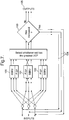
- Figure 2 illustrates the construction of a paraunitary matrix H N ( z ) as a product of N+1 elementary paraunitary matrices in accordance with the invention.
- An elementary paraunitary matrix is an expression coined for the purposes of the present invention: it is defined as a polynomial matrix which represents applying a set of delays to the signals, followed by a single unitary transformation (rotation); as will be described later in more detail, this definition may optionally include the rotation being followed by a further set of delays (omitted in the present example).
- Rotation single unitary transformation
- Each of the blocks V 0 (z) to V N (z) implements a respective 2 by 2 elementary paraunitary matrix which itself implements a Givens rotation.
- signals in the upper and lower channels 30 and 31 pass into a matrix of four ganged single pole double throw switches 32 controlling routing or otherwise via a delay cell Z d0 .
- the switches 32 are all either in the UP position or in the DOWN position: when DOWN, upper channel signals are delayed at Z d0 but lower channel signals are not, and when UP the reverse is the case. This enables either channel 30 or 31 to be delayed relative to the other.
- the progress of imposing wide sense decorrelation upon signals in accordance with the invention uses a cost function that is calculated after every application of an elementary paraunitary matrix to the signals to determine whether or not an improvement has been achieved.
- the cost function is a measure of the signals' strong decorrelation, an example of which is a sum squared of second order measures of autocorrelation of the signals, and is at a maximum when all cross-correlation terms are at a minimum. Thus an increase in this cost function corresponds to a reduction in correlation between the signals.
- the cost function will be referred to as the Decorrelation Cost Function (hereinafter "DCF").
- the process of the invention is to find an appropriate paraunitary matrix that imposes wide sense decorrelation on the signals.
- This matrix is not parameterised as disclosed by Vaidyanathan, but it is instead parameterised in terms of elementary paraunitary matrices (see Equation (17)) calculated sequentially.
- each elementary paraunitary matrix is applied to the signals used to calculate it: this transforms the signals into a form suitable for calculating the next such matrix.
- a latest elementary paraunitary matrix is chosen which maximises the DCF calculated for signals transformed by application of all such matrices calculated up and including the latest.
- To identify the latest elementary paraunitary matrix its delay and rotation parameters are required. There is a countable infinity of different possible delays, but an uncountable number of different rotation parameters. Realistically the countable infinity of possible delays will be reduced to a finite number of different delays to be considered, either by constraining them or by making the assumption of circulant statistics and hence constraining them to be less than the data length (number of samples of each signal used in decorrelation).
- rotation parameters s 0 and c 0 are chosen. These parameters could be chosen by using a technique which explicitly maximises the DCF of output signals.
- the elementary paraunitary matrix that is selected is that having the best DCF output. This stage is repeated until there is no gain in DCF to be found, or the gain in DCF is regarded as being too small to warrant the extra complexity in the strongly decorrelating matrix.
- the invention can be seen as a method of imposing wide sense decorrelation by sequentially applying a series of elementary paraunitary matrices each chosen to maximise an DCF measure in an output resulting from its use.
- Each elementary paraunitary matrix contains one rotation.
- the process of the invention implements an algorithm referred to as the Sequential Best Rotation (SBR) algorithm.
- SBR Sequential Best Rotation
- This algorithm comprises decomposition of the paraunitary matrix into elementary paraunitary matrices, and the use of a measure which can be meaningfully calculated at each stage of the algorithm not just at the end. The combination of these two steps separates the algorithm into a series of like stages that can be carried out in sequence.
- Strong decorrelation of signals is equivalent to a process of generating a strongly decorrelating matrix H ( z ).
- H ( z ) It is not essential to generate H ( z ), but it permits the process to be tested: i.e. mixed signals which have undergone a prearranged form of convolutive mixing can be used to produce H ( z ), and then H ⁇ ( z ), the paraconjugate of H ( z ), can be compared with the prearranged form to see how faithfully the former reconstructs the latter.
- H ( z ) can be used to determine further information about original signals, such as arrival direction and frequency response.
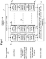
- FIG. 3 a flow diagram is shown illustrating an iterative process of the invention to produce a strongly decorrelating polynomial paraunitary matrix H ( z ) as the product of a series of elementary paraunitary matrices.
- H ( z ) the product of a series of elementary paraunitary matrices.
- h ( z ) represents the transformation which converts the original input mixed signals to obtain the current signals: it is improved repeatedly until applying a further elementary paraunitary matrix results in no significant improvement in DCF, at which point h ( z ) has become H ( z ).
- the process starts at 60, where the initial current signals are the original input signals, and the initial current value of the paraunitary matrix h ( z ) is the identity matrix I .
- the current signals are used to produce a current elementary paraunitary matrix; at 62 this matrix is applied to the current signals to produce new signals.
- the new signals are tested to see whether their strong decorrelation properties have improved: if such an improvement has been obtained, at 64 the current elementary paraunitary matrix is used to pre-multiply h ( z ) to provide the latest current value of the evolving paraunitary matrix and the new signals become the latest current signals.
- the latest current value of h ( z ) and the latest current signals are then fed back to stage 61 for the procedure of stages 61, 62 and 63 to be repeated.
- the process is considered to have converged to a solution and it terminates at 65: the current value of h ( z ) is output as H ( z ) and the current signals are output as the required strongly decorrelated signals.
- the use of elementary paraunitary matrices divides the problem of strongly decorrelating signals and obtaining H ( z ) into a number of sub-problems.
- N 1 L Decorrelation cost functions, denoted by N 1 L , are defined as the sum squared of all possible correlation terms in a set of signals.
- correlations are derived between each signal in the set and a relatively delayed replica of itself, i.e. there are no correlations between different signals: x 1 and x 2 in Equation (18) are therefore the same signal with a relative delay therebetween, and correlations are obtained for each of a set of delays up to a maximum delay of L.
- L Changing the L value changes the properties of N 1 L , but for all values of L this is a sensible decorrelation cost function.
- the process of the invention may use any convenient DCF, provided it is an accurate DCF and is used consistently throughout: specific problems may suggest specific DCFs.
- the parameter d is a vector parameter
- ⁇ can be a vector parameter if there are more than two signals.
- ⁇ is not a vector.
- D 0 A , 0 A ⁇ 1 , ⁇ ⁇ ⁇ ⁇ ⁇ 0 1 , 0 0 , 1 0 , ⁇ ⁇ ⁇ ⁇ ⁇ A ⁇ 1 0 , A 0 where dots indicate terms not shown, each inner pair of parentheses represents a delay vector ⁇ i having two elements, 0 in an upper or lower position in parentheses indicates an undelayed upper or lower signal channel respectively, and a non-zero value in such a position indicates a delayed channel located likewise: each non-zero value represents delaying the associated channel in each case relative to the other channel by an integer value not greater than A.
- Delays are in units of a time interval ⁇ between successive signal samples, e.g. a delay ( A - 1) implies ( A - 1) ⁇ .
- D The number of elements or delay values in D is S , i.e.
- S .
- FIG. 4 there is shown a flow diagram indicating how elementary paraunitary matrices can be found.
- respective elementary paraunitary matrices are derived, and then the DCFs of the signals these matrices create are calculated.
- the elementary paraunitary matrix corresponding to the best DCF is then selected for use.
- a pair of current signals are input at 70.
- the signals are replicated S times, i.e. as many times as there are delay values in D .
- each replica is a pair of current signals: each replica pair is input to a respective signal channel 72 i of which there are S , i.e.
- the relative delay produces a pair of signals that are different from those input at 70, although they are no more strongly decorrelated than before.
- Each channel 72 i now has parameters associated with it consisting of a delay vector ⁇ i and a rotation angle ⁇ i , just as if an elementary paraunitary matrix implementing those parameters had been applied to the signals input at 70: moreover, when applied to input signals this matrix provides a rotation which produces output signals that are as decorrelated as they can be for the relevant value of delay element ⁇ i .
- the next stage is to determine which of the channels 72 1 to 72 S simulates an elementary paraunitary matrix producing the highest improvement in strong decorrelation. This is carried out at 76 1 to 76 S , where DCFs of signals output from stages 75 1 to 75 S respectively are calculated. These DCFs are compared with one another at 77, and whichever channel produces the greatest DCF provides the highest improvement in strong decorrelation and simulates the best elementary paraunitary matrix: this matrix is selected as the output of the process indicated in Figure 4 for use at 61 in Figure 3 .
- the delay which leads to the maximum cross correlation between the two signals can be selected, without having to apply delays and calculate rotations for each of the channels.
- the foregoing embodiment of the invention related to imposing wide sense decorrelation in a two-channel case, i.e. two signal sources, two receivers and two paths from each source to receivers. If there are more than two channels further processing is necessary.
- the procedure of the invention remains fundamentally the same: i.e. find a paraunitary matrix to impose strong decorrelation on signals in the channels, the matrix being a product of successive elementary paraunitary matrices each of which maximises a measure of strong decorrelation of outputs resulting from its application to input signals.
- Equation (20) involves the same problems as in the two-channel case described with reference to Figure 1 .
- the procedure used to deal with the problems is the decomposition of a paraunitary matrix into elementary paraunitary matrices: the elementary paraunitary matrices are found by considering the decomposition and constraining all but one rotation. One rotation is unconstrained, but all others are constrained to either leave inputs unchanged or to reorder channels so a different channel receives a subsequent delay. Thus all rotations apart from one are constrained to be permutations.
- P i is the ith permutation matrix and R ⁇ is the rotation matrix parameterised by a vector of n(n-1)/2 rotation angles ⁇ .
- D d is the delay matrix.
- Its index, d is a length n vector whose n elements are delays applied in respective channels.
- Equation (21) shows the extended form of an elementary paraunitary matrix.
- a delay matrix is applied, which consists of differing delays being applied in all the channels.
- a rotation is applied.
- this is a good choice for an elementary building block, as it contains only one operation that mixes the signals.
- this form is parameterisable, the parameters being the vectors d and ⁇ .
- the methodology for finding this expansion is largely the same as in the two-channel case. It only requires modification in selecting D , i.e. the delay set or set of possible delays for forming the first of the series of elementary paraunitary matrices.
- D the delay set or set of possible delays for forming the first of the series of elementary paraunitary matrices.
- the elements of D were treated as delays applied to only one channel.
- delays are allowed in more than one channel.
- a sensible finite set has to be selected to form D .
- the number of elements in D could be fixed by setting an upper limit denoted by l to the number of delays in it.
- D can consist of all possible ways of allocating up to I delays between n channels. Applying the same delay to all channels at the same time is equivalent to applying no delay at all, so all elements in D should have at least one channel that is not delayed.
- the number of elements in D can grow very fast as n and l increase. As before this scheme for D is merely selection of a sensible option. Other possibilities exist but usually need more justification to ensure validity. It is possible to justify some choices (such as allowing delays to be applied to only one channel) by saying they allow a higher l for a fixed size of D . Thus they allow the algorithm to consider longer delays, at the cost of not allowing it to implement more complicated combinations of smaller delays.
- the process of the invention can proceed to impose wide sense decorrelation in the multi-channel case in a similar way to the two-channel case of the previous embodiment.
- the two-element delay vectors ⁇ i in Figure 4 are replaced by delay vectors (elements of the delay set D ) having n elements, where n is the number of channels. This allows the algorithm to apply an element of D to the signals.
- the rotations calculated by known pointwise decorrelation algorithms at stages 75 1 to 75 S are now n channel rotations.
- This approach to the multi-channel case may give difficulty over the size of the delay set D : because each element in D is a vector, for each element a whole n by n pointwise decorrelation algorithm has to be carried out. As the delay set upper limit l grows this becomes the dominant time constraint and slows processing down. So-called "sweeping" algorithms were developed in the prior art to attempt to mitigate similar problems in the instantaneous case.
- This example of the invention provides a procedure called the sweeping process for finding an elementary paraunitary matrix based algorithm that follows the same approach used in the Jacobi algorithm.
- the procedure has a prearranged ordering of all available signal pairings through which it works in a sweep.
- Each signal pair is processed using the two-channel process of the first embodiment of the invention.
- the remaining signals are aligned in time (delayed) so they have at least approximately the same delay applied to them as the signal pair being processed.
- the same termination condition from the previous embodiment of the invention can be applied to decide if another sweep needs to be carried out or if no more significant improvement is obtainable.
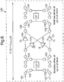
- Figure 6 illustrates this procedure for imposing wide sense decorrelation on three signals A, B and C.
- the process of the invention implements the Sequential Best Rotation or SBR algorithm.
- SBR2 indicates application of the SBR algorithm for a two-channel case as in the previous embodiment.
- signals A and B are processed with SBR2 at 90, and at 91 signal C is aligned in time for substantial synchronisation with the output from 90.
- the elementary paraunitary matrices implement only one set of delays, and time alignment at 91 is carried out by delaying C by half the order of the polynomial matrix determined at 90.
- C is delayed in time by half the sum total of the delays applied in the processing of A and B irrespective of which channel the or (as the case may be) each delay lies in. Alignment of C in this way is not essential but has been found to give acceptable results.
- the or each matrix applies rotation and delay to signals A and B but it applies a delay to signal C without rotating it. If more than one elementary paraunitary matrix is determined at 90, all delays applied to signal C must add up to the total delay applied to C at 91.
- signal B (after processing at 90) and signal C (after delay at 91) are processed with SBR2 at 92, and signal A (after processing at 90) is aligned in time at 93 with the output from 92.
- signal A (after alignment at 93) and signal C (after processing at 92) are processed with SBR2 at 94, and signal B (after processing at 92) is aligned in time at 95 with the output from 94.
- the next stage at 96 is to determine whether or not the signals have become sufficiently strongly decorrelated to warrant terminating the process, or whether it is necessary to continue: as before this termination condition is satisfied if DCFs of the signals have not improved significantly: if so, processing terminates; if not a respective elementary paraunitary matrix determined at each of 90, 92 and 94 is used to pre-multiply a stored product of those preceding it and the latest resulting product replaces that previously stored; the latest current signals from SBR2 94 and alignment 95 are then fed back to 90 and 91 via a feedback loop 97 for the procedure to be repeated.
- one or more two-channel elementary paraunitary matrices may be applied in the SBR2 stages at 90, 92 and 94 for each circulation round the loop of items 90 to 97. It is possible to apply as many elementary paraunitary matrices at these stages as one wishes, up to the number necessary to meet the termination condition for the SBR2 algorithm. It is preferred to apply only one elementary paraunitary matrix at the stages 90, 92 and 94 because it reduces the need for signal alignment at 91, 93 and 95: it uses the philosophy of applying the more important rotations first, because earlier rotations in the SBR2 process tend to give more performance gain than later equivalents.
- signals A and B are processed with SBR2, and, in this example using elementary paraunitary matrices with one set of delays, signal C is aligned in time with the output so produced.
- signal C is aligned in time with the output so produced.
- a (or as the case may be each) two channel elementary paraunitary matrix produced by the application of SBR2 to two signal channels is extended to an n channel elementary paraunitary matrix that delays (but does not rotate) the or each remaining signal C to preserve time alignment with SBR2-processed signals A and B.
- signals A and C are processed with SBR2, and signal B is aligned with the output.
- signals B and C are processed with SBR2 at 94, and signal A is aligned with the output.
- the DCFs of the three output signal groups are determined: the group with the greatest DCF is selected, and if the DCF shows an improvement over the input signals to this stage, then the operation is accepted.
- the SBR2 steps 100, 101 and 102 may consist of applying a full SBR2 process of calculating a series of, elementary paraunitary matrices until no improvement is obtained, or just finding one elementary paraunitary matrix.
- the latter case is equivalent to a restricted version of a full SBR: i.e. ignoring time alignment, the delays are restricted to only delaying one channel and the rotations to only applying a rotation to the delayed channel and one other. This reduces the size of the delay set and hence increases the speed of computation of elementary paraunitary matrices.
- a more general definition of an elementary paraunitary matrix is a polynomial matrix which represents applying an initial set of delays to input signals, then applying a single unitary transformation (rotation) to the delayed input signals, followed by applying a further set of delays to the delayed and rotated input signals.
- the initial set of delays is defined as the leading delays and the further set of delays as the terminal delays.
- Figure 8 illustrates a single elementary paraunitary matrix implementation 120 of this new form: as in Figures 2 and 3 this implementation is shown for a two channel case for the sake of simplicity.
- signals in upper and lower channels 121 and 122 pass into a matrix of four ganged single pole double throw switches 123 controlling routing or otherwise via a delay cell Z di .
- the switches 123 are all either in the UP position or in the DOWN position: when DOWN, upper channel signals are delayed at Z di but lower channel signals are not, and when UP the reverse is the case. This enables either channel 121 or 122 to be delayed relative to the other.
- an upper channel signal is multiplied by Givens rotation parameters -s i and c i at amplifiers 124 and 125 respectively.
- a lower channel signal is multiplied by Givens rotation parameters s i and c i at amplifiers 126 and 127 respectively.
- s i and c i are respectively the sine and cosine of a rotation angle ⁇ i implemented at 120.
- Each c i product is summed with the s i or -s i product involving the signal from the other channel: this provides sums which pass along respective channels 128 and 129 to another matrix of four ganged single pole double throw switches 130 controlling routing or otherwise via a delay cell Z ⁇ i .
- the process of the invention using the new or type 2 elementary paraunitary matrices to find an appropriate paraunitary matrix that imposes wide sense decorrelation on the signals is very similar to that previously described.
- the appropriate paraunitary matrix is not parameterised as disclosed by Vaidyanathan, but it is instead parameterised in terms of elementary paraunitary matrices (see Equation (23)) calculated sequentially.
- each elementary paraunitary matrix is applied to the signals used to calculate it: this transforms the signals into a form suitable for calculating the next such matrix.
- a delay pair is defined as a pair of delays, one the leading delay and the other the terminal delay, used in an elementary paraunitary matrix.
- To calculate an elementary paraunitary matrix a set of possible delay pairs is considered.
- a latest elementary paraunitary matrix is chosen which maximises the DCF calculated for signals transformed by application of all such matrices calculated up and including the latest.
- To identify the latest elementary paraunitary matrix its delay and rotation parameters are required. There is a countable infinity of different possible delays, but an uncountable number of different rotation parameters.
- the countable infinity of possible delays will be reduced to a finite number of different delays to be considered, either by constraining them or by making the assumption of circulant statistics and hence constraining them to be less than the data length (number of samples of each signal used in decorrelation). If type 1 or type 2 elementary paraunitary matrices (as defined above) are to be used the terminal delays are fixed by the value of the leading delays.
- rotation parameters s i and c i are chosen. These parameters could be chosen by using a technique which explicitly maximises the DCF of output signals.
- the elementary paraunitary matrix that is selected is that having the best DCF output. This stage is repeated until there is no gain in DCF to be found, or the gain in DCF is regarded as being too small to warrant the extra complexity in the strongly decorrelating matrix.
- the additional parameter ⁇ results in a small change as compared to the process described with reference to Figure 4 .
- the equations and procedures given in the foregoing description can clearly be implemented by an appropriate computer program comprising program instructions on an appropriate carrier medium and running on a conventional computer system.
- the carrier medium may be a memory, a floppy or compact or optical disc or other hardware recordal medium, or an electrical signal.
- Such a program is straightforward for a skilled programmer to implement from the foregoing description without requiring invention, because it involves well known computational procedures.
Landscapes
- Engineering & Computer Science (AREA)
- Computer Vision & Pattern Recognition (AREA)
- Data Mining & Analysis (AREA)
- Theoretical Computer Science (AREA)
- Bioinformatics & Computational Biology (AREA)
- Bioinformatics & Cheminformatics (AREA)
- Artificial Intelligence (AREA)
- Evolutionary Biology (AREA)
- Evolutionary Computation (AREA)
- Physics & Mathematics (AREA)
- General Engineering & Computer Science (AREA)
- General Physics & Mathematics (AREA)
- Life Sciences & Earth Sciences (AREA)
- Complex Calculations (AREA)
Claims (28)
- Durch einen Computer implementiertes Verfahren von starker Dekorrelation von Signalen, die von Sensoren erhalten werden und die Eingangssignale sind, wobei die starke Dekorrelation eine Dekorrelation mit Zeitverzögerungen umfasst, dadurch gekennzeichnet, dass es die Schritte enthält zum:a) Verarbeiten der Eingangssignale, um Verzögerungs- und Drehungsparameter zu bestimmen, die mindestens eine elementare paraunitäre Matrix implementieren, die eine Matrix ist, die die Identitätsmatrix angibt, wenn sie mit ihrer parakonjugierten Matrix multipliziert wird, und zum Umwandeln der Eingangssignale in Ausgangssignale, um eine Verbesserung in einer Messung von starker Dekorrelation zu erhalten;b) Bewerten der Verbesserung in der Messung von starker Dekorrelation, und wenn sie signifikant ist, zum Festlegen der Ausgangssignale als Eingangssignale und Wiederholen von Schritt a) und diesem Schritt b);c) wenn die Verbesserung nicht signifikant ist, Festlegen der Ausgangssignale als dekorrelierte Signale in einem weiten Sinn.
- Durch einen Computer implementiertes Verfahren nach Anspruch 1, dadurch gekennzeichnet, dass die Verzögerungs- und Drehungsparameter, die die Eingangssignale umwandeln, eine einzelne elementare paraunitäre Matrix kennzeichnen.
- Durch einen Computer implementiertes Verfahren nach Anspruch 2, dadurch gekennzeichnet, dass es ein Erzeugen einer paraunitären Matrix durch kumulatives Multiplizieren von aufeinander folgenden elementaren paraunitären Matrizen enthält, die durch Wiederholen von Schritt a) erzeugt werden.
- Durch einen Computer implementiertes Verfahren nach Anspruch 2, dadurch gekennzeichnet, dass der Bereich von Signalverzögerungsparametern eine Gruppe von diskreten Verzögerungsvektoren ist, und die Verzögerungs- und Drehungsparameter durch Generieren einer jeweiligen Version der Eingangssignale, die durch jeden Verzögerungsvektor in der Gruppe verzögert werden, und Suchen von Drehungsparametern für jede Version bestimmt werden, die sich mindestens einem Erzeugen einer Maximierung von starker Dekorrelation der Ausgangssignale nähern.
- Durch einen Computer implementiertes Verfahren nach Anspruch 4, dadurch gekennzeichnet, dass die Drehungsparameter, die sich mindestens einem Erzeugen einer Maximierung von starker Dekorrelation der Ausgangssignale nähern, unter Verwendung eines Algorithmus für punktweise Dekorrelation der Art bestimmt werden, die bei unverzögerter Dekorrelation verwendet wird.
- Durch einen Computer implementiertes Verfahren nach Anspruch 1, das n Eingangssignale umfasst, wobei n eine Ganzzahl größer 2 ist, dadurch gekennzeichnet, dass der Bereich von Signalverzögerungsparametern eine Gruppe von n Elementverzögerungsvektoren ist, und der Bereich von Signaldrehungsparametern eine Gruppe von n(n - 1)/2 Winkelparametern ist.
- Durch einen Computer implementiertes Verfahren nach Anspruch 1, das n Eingangssignale umfasst, wobei n eine Ganzzahl größer 2 ist, dadurch gekennzeichnet, dass Schritt a) ein Bestimmen von Verzögerungs- und Drehungsparametern aufweist, die mindestens eine elementare paraunitäre Matrix implementieren, die für eine Drehung eines Paars von Eingangssignalen und eine relative Verzögerung des oder gegebenenfalls jedes anderen Eingangssignals sorgt.
- Durch einen Computer implementiertes Verfahren nach Anspruch 7, wobei die n Eingangssignale jeweiligen Kanälen zugehörig sind, dadurch gekennzeichnet, dass Schritt a) n(n - 1)/2 aufeinander folgende Stufen hat, die jeweils mindestens einer jeweiligen elementaren paraunitären Matrix zugehörig sind, und jeweils für eine Drehung von Signalen, die einem jeweiligen Paar von Kanälen zugehörig sind, und eine Bereitstellung einer relativen Verzögerung sorgen, die dem oder gegebenenfalls jedem anderen Kanal zugehörig ist, die erste Stufe so angeordnet ist, dass die Eingangssignale verarbeitet werden und die oder gegebenenfalls jede nachfolgende Stufe angeordnet ist, um Signale zu empfangen, die in der jeweils vorhergehenden Stufe verarbeitet wurden.
- Durch einen Computer implementiertes Verfahren nach Anspruch 1, das eine Gruppe von n Eingangssignalen umfasst, wobei n eine Ganzzahl größer 2 ist, dadurch gekennzeichnet, dass es aufweist:a) ein Erzeugen von n(n - 1)/2 Kopien der Gruppe von Eingangssignalen,b) in jeder Kopie ein Auswählen eines jeweiligen Signalpaars, das sich von denjenigen unterscheidet, die in anderen Kopien ausgewählt werden, undc) den Schritt zum Verarbeiten der Eingangssignale zum Bestimmen von Verzögerungs- und Drehungsparametern, der für jede Kopie ausgeführt wird und aufweist:i) ein Bestimmen von Verzögerungs- und Drehungsparametern, die mindestens eine elementare paraunitäre Matrix implementieren, die für eine Drehung nur des jeweiligen ausgewählten Signals sorgt, undii) ein Bestimmen, welche Kopie, wenn sie durch die zugehörige mindestens eine elementare paraunitäre Matrix umgewandelt wird, zu umgewandelten Signalen führt, die einer Verbesserung in einer Messung von Dekorrelation um mindestens einen großen Teil eines maximalen Ausmaßes zugehörig sind, die über die Kopien erhaltbar ist, und ein Festlegen dieser umgewandelten Signale als Ausgangssignale.
- Durch einen Computer implementiertes Verfahren nach Anspruch 1, dadurch gekennzeichnet, dass die mindestens eine elementare paraunitäre Matrix mindestens eine vorangehende Verzögerung, Drehungs- und Endverzögerung implementiert.
- Computervorrichtung für starke Dekorrelation von Signalen, wobei die starke Dekorrelation eine Dekorrelation mit Zeitverzögerungen umfasst, wobei die Vorrichtung für ein Empfangen von Eingangssignalen programmiert ist, die von Sensoren erhalten werden, dadurch gekennzeichnet, dass die Vorrichtung ferner programmiert ist zum:a) Verarbeiten der Eingangssignale, um Verzögerungs- und Drehungsparameter zu bestimmen, die mindestens eine elementare paraunitäre Matrix implementieren, die eine Matrix ist, die die Identitätsmatrix angibt, wenn sie mit ihrer parakonjugierten Matrix multipliziert wird, und zum Umwandeln der Eingangssignale in Ausgangssignale, um eine Verbesserung in einer Messung von starker Dekorrelation zu erhalten;b) Bewerten der Verbesserung in der Messung von starker Dekorrelation, und wenn sie signifikant ist, zum Festlegen der Ausgangssignale als Eingangssignale und Wiederholen von a) und b);c) wenn die Verbesserung nicht signifikant ist, Festlegen der Ausgangssignale als dekorrelierte Signale in einem weiten Sinn.
- Vorrichtung nach Anspruch 11, dadurch gekennzeichnet, dass die Verzögerungs-und Drehungsparameter, die die Eingangssignale umwandeln, eine einzelne elementare paraunitäre Matrix kennzeichnen.
- Vorrichtung nach Anspruch 12, dadurch gekennzeichnet, dass die Computerausrüstung programmiert ist, eine paraunitäre Matrix durch kumulatives Multiplizieren von aufeinander folgenden elementaren paraunitären Matrizen zu erzeugen, die in einer iterativen Verarbeitung zu erzeugt werden.
- Vorrichtung nach Anspruch 12, dadurch gekennzeichnet, dass der Bereich von Signalverzögerungsparametern eine Gruppe von diskreten Verzögerungsvektoren ist, und die Computerausrüstung programmiert ist, die Verzögerungs- und Drehungsparameter durch Generieren einer jeweiligen Version der Eingangssignale zu bestimmen, die durch jeden Verzögerungsvektor in der Gruppe verzögert werden, und für jede Version Drehungsparameter zu suchen, die sich mindestens einem Erzeugen einer Maximierung von starker Dekorrelation der Ausgangssignale nähern.
- Vorrichtung nach Anspruch 14, dadurch gekennzeichnet, dass die Computerausrüstung programmiert ist, die Drehungsparameter zu bestimmen, die sich mindestens einem Erzeugen einer Maximierung von starker Dekorrelation der Ausgangssignale nähern, wobei ein Algorithmus für punktweise Dekorrelation verwendet wird.
- Vorrichtung nach Anspruch 11, die programmiert ist zum Empfangen von n Eingangssignalen, wobei n eine Ganzzahl größer 2 ist, dadurch gekennzeichnet, dass die Vorrichtung ferner programmiert ist zum Bestimmen von Verzögerungs- und Drehungsparametern, die mindestens eine elementare paraunitäre Matrix implementieren, die für eine Drehung eines Paars von Eingangssignalen und eine relative Verzögerung des oder gegebenenfalls jedes anderen Eingangssignals sorgt.
- Vorrichtung nach Anspruch 16, die programmiert ist, um jeweilige Kanäle für die n Eingangssignale zu definieren, dadurch gekennzeichnet, dass die Vorrichtung ferner programmiert ist, die Eingangssignale in (n - -1)/2 aufeinander folgenden Stufen zu verarbeiten, die jeweils mindestens einer jeweiligen elementaren paraunitären Matrix zugehörig sind, und jeweils für eine Drehung von Signalen, die einem jeweiligen Paar von Kanälen zugehörig sind, und eine Bereitstellung einer relativen Verzögerung zu sorgen, die dem oder gegebenenfalls jedem anderen Kanal zugehörig ist, wobei die erste derartige Stufe ein Verarbeiten der Eingangssignale umfasst und die oder gegebenenfalls jede nachfolgende Stufe ein Verarbeiten von Signalen umfasst, die aus der jeweils vorhergehenden Stufe stammen.
- Vorrichtung nach Anspruch 11, die programmiert ist zum Empfangen einer Gruppe von n Eingangssignalen, wobei n eine Ganzzahl größer 2 ist, dadurch gekennzeichnet, dass die Vorrichtung ferner programmiert ist zum:a) Erzeugen von n(n - 1)/2 Kopien der Gruppe von Eingangssignalen,b) Auswählen eines jeweiligen Signalpaars in jeder Kopie, das sich von denjenigen unterscheidet, die in anderen Kopien ausgewählt werden, undc) Implementieren einer Verarbeitung der Eingangssignale zum Bestimmen von Verzögerungs- und Drehungsparametern für jede Kopie als Eingangssignale und Bestimmen:i) von Verzögerungs- und Drehungsparametern, die mindestens eine elementare paraunitäre Matrix implementieren, die für eine Drehung nur des jeweiligen ausgewählten Signalpaars sorgt, undii) welche Kopie, wenn sie durch die zugehörige mindestens eine elementare paraunitäre Matrix umgewandelt wird, zu umgewandelten Signalen führt, die einer Verbesserung in einer Messung von Dekorrelation um mindestens einen großen Teil eines maximalen Ausmaßes zugehörig sind, die über die Kopien erhaltbar ist, und Festlegen dieser umgewandelten Signale als Ausgangssignale.
- Vorrichtung nach Anspruch 11, dadurch gekennzeichnet, dass die mindestens eine elementare paraunitäre Matrix mindestens eine vorangehende Verzögerung, Drehungs- und Endverzögerung implementiert.
- Computerprogramm zum Implementieren von starker Dekorrelation von Signalen, die von Sensoren erhalten werden und in eine Computervorrichtung eingegeben werden, wobei die starke Dekorrelation eine Dekorrelation mit Zeitverzögerungen umfasst, dadurch gekennzeichnet, dass das Computerprogramm Anweisungen zum Steuern der Computervorrichtung hat:a) zum Verarbeiten der Eingangssignale, um Verzögerungs- und Drehungsparameter zu bestimmen, die mindestens eine elementare paraunitäre Matrix implementieren, die eine Matrix ist, die die Identitätsmatrix angibt, wenn sie mit ihrer parakonjugierten Matrix multipliziert wird, und zum Umwandeln der Eingangssignale in Ausgangssignale, um eine Verbesserung in einer Messung von starker Dekorrelation zu erhalten;b) zum Bewerten der Verbesserung in der Messung von starker Dekorrelation, und wenn sie signifikant ist, zum Festlegen der Ausgangssignale als Eingangssignale und Wiederholen von a) und b);c) wenn die Verbesserung nicht signifikant ist, zum Festlegen der Ausgangssignale als dekorrelierte Signale in einem weiten Sinn.
- Computerprogramm nach Anspruch 20, dadurch gekennzeichnet, dass die Verzögerungs- und Drehungsparameter, die die Eingangssignale umwandeln, eine einzelne elementare paraunitäre Matrix kennzeichnen.
- Computerprogramm nach Anspruch 21, dadurch gekennzeichnet, dass es angeordnet ist, um die Computerausrüstung zu steuern, den Schritt zum Erzeugen einer paraunitären Matrix durch kumulatives Multiplizieren von aufeinander folgenden elementaren paraunitären Matrizen zu implementieren, die durch ein iteratives Verarbeiten der Eingangssignale erzeugt werden, um Verzögerungs- und Drehungsparameter zu bestimmen.
- Computerprogramm nach Anspruch 21, dadurch gekennzeichnet, dass der Bereich von Signalverzögerungsparametern eine Gruppe von diskreten Verzögerungsvektoren ist, und das Computerprogramm angeordnet ist, um für die zu bestimmenden Verzögerungs- und Drehungsparameter durch Generieren einer jeweiligen Version der Eingangssignale, die durch jeden Verzögerungsvektor in der Gruppe verzögert werden, und durch Suchen von Drehungsparametern für jede Version zu sorgen, die sich mindestens einem Erzeugen einer Maximierung von starker Dekorrelation der Ausgangssignale nähern.
- Computerprogramm nach Anspruch 23, dadurch gekennzeichnet, dass es angeordnet ist, um für die Drehungsparameter zu sorgen, die sich mindestens einem Erzeugen einer Maximierung von zu bestimmender starker Dekorrelation der Ausgangssignale nähern, wobei ein Algorithmus für punktweise Dekorrelation verwendet wird.
- Computerprogramm nach Anspruch 20, das angeordnet ist, um eine Computerausrüstung zu steuern, n Eingangssignale zu empfangen, wobei n eine Ganzzahl größer 2 ist, dadurch gekennzeichnet, dass es angeordnet ist, um für eine Verarbeitung der Eingangssignale zum Bestimmen von Verzögerungs- und Drehungsparametern zu sorgen, um ein Bestimmen derartiger Parameter aufzuweisen, die mindestens eine elementare paraunitäre Matrix implementieren, die für eine Drehung eines Paars von Eingangssignalen und eine relative Verzögerung des oder gegebenenfalls jedes anderen Eingangssignals sorgt.
- Computerprogramm nach Anspruch 25, das angeordnet ist, um eine Computerausrüstung zu steuern, jeweilige Kanäle für die n Eingangssignale zu definieren, dadurch gekennzeichnet, dass es angeordnet ist, für die Verarbeitung der Eingangssignale zu sorgen, um zu bestimmen, dass Verzögerungs- und Drehungsparameter (n - 1)/2 aufeinander folgende Stufen haben, die jeweils mindestens einer jeweiligen elementaren paraunitären Matrix zugehörig sind und jeweils für eine Drehung von Signalen, die einem jeweiligen Paar von Kanälen zugehörig sind, und eine Bereitstellung einer relativen Verzögerung zu sorgen, die dem oder gegebenenfalls jedem anderen Kanal zugehörig ist, wobei die erste Stufe angeordnet ist, die Eingangssignale und die oder gegebenenfalls jede nachfolgende Stufe zu verarbeiten, die angeordnet ist, um Signale zu empfangen, die aus der jeweils vorhergehenden Stufe stammen.
- Computerprogramm nach Anspruch 20, das angeordnet ist, um eine Computerausrüstung zu steuern, ein Gruppe von n Eingangssignalen zu empfangen, wobei n eine Ganzzahl größer 2 ist, dadurch gekennzeichnet, dass es ferner für eine derartige Ausrüstung sorgt zum:a) Erzeugen von n(n - 1)/2 Kopien der Gruppe von Eingangssignalen,b) Auswählen eines jeweiligen Signalpaars in jeder Kopie, das sich von denjenigen unterscheidet, die in anderen Kopien ausgewählt werden, undc) Ausführen einer Verarbeitung zum Bestimmen von Verzögerungs- und Drehungsparametern für jede Kopie als Eingangssignale durch:i) ein Bestimmen von Verzögerungs- und Drehungsparametern, die mindestens eine elementare paraunitäre Matrix implementieren, die für eine Drehung nur des jeweiligen ausgewählten Signalpaars sorgt, undii) ein Bestimmen, welche Kopie, wenn sie durch die zugehörige mindestens eine elementare paraunitäre Matrix umgewandelt wird, zu umgewandelten Signalen führt, die einer Verbesserung in einer Messung von starker Dekorrelation um mindestens einen großen Teil eines maximalen Ausmaßes zugehörig sind, die über die Kopien erhaltbar ist, und ein Festlegen dieser umgewandelten Signale als Ausgangssignale.
- Computerprogramm nach Anspruch 20, dadurch gekennzeichnet, dass die mindestens eine elementare paraunitäre Matrix mindestens eine vorangehende Verzögerung, Drehungs- und Endverzögerung implementiert.
Applications Claiming Priority (3)
| Application Number | Priority Date | Filing Date | Title |
|---|---|---|---|
| GB0228163 | 2002-12-03 | ||
| GBGB0228163.2A GB0228163D0 (en) | 2002-12-03 | 2002-12-03 | Decorrelation of signals |
| PCT/GB2003/005168 WO2004051501A2 (en) | 2002-12-03 | 2003-11-26 | Decorrelation of signals |
Publications (2)
| Publication Number | Publication Date |
|---|---|
| EP1588315A2 EP1588315A2 (de) | 2005-10-26 |
| EP1588315B1 true EP1588315B1 (de) | 2019-06-05 |
Family
ID=9948975
Family Applications (1)
| Application Number | Title | Priority Date | Filing Date |
|---|---|---|---|
| EP03777016.1A Expired - Lifetime EP1588315B1 (de) | 2002-12-03 | 2003-11-26 | Dekorrelation von signalen |
Country Status (6)
| Country | Link |
|---|---|
| US (1) | US7299161B2 (de) |
| EP (1) | EP1588315B1 (de) |
| JP (1) | JP4550585B2 (de) |
| AU (1) | AU2003286273A1 (de) |
| GB (1) | GB0228163D0 (de) |
| WO (1) | WO2004051501A2 (de) |
Families Citing this family (8)
| Publication number | Priority date | Publication date | Assignee | Title |
|---|---|---|---|---|
| JP2005201869A (ja) * | 2004-01-19 | 2005-07-28 | Mitsutoyo Corp | 信号処理方法、信号処理プログラム、この信号処理プログラムを記録した記録媒体および信号処理装置 |
| US20050182500A1 (en) * | 2004-02-17 | 2005-08-18 | Continuous Control Solutions, Inc. | Time delay definition |
| SE0402652D0 (sv) * | 2004-11-02 | 2004-11-02 | Coding Tech Ab | Methods for improved performance of prediction based multi- channel reconstruction |
| US7873016B2 (en) * | 2005-11-07 | 2011-01-18 | Broadcom Corporation | Method and system for utilizing tone grouping with givens rotations to reduce overhead associated with explicit feedback information |
| US8233552B2 (en) * | 2005-11-07 | 2012-07-31 | Broadcom Corporation | Method and system for utilizing givens rotation expressions for asymmetric beamforming matrices in explicit feedback information |
| US8374854B2 (en) * | 2008-03-28 | 2013-02-12 | Southern Methodist University | Spatio-temporal speech enhancement technique based on generalized eigenvalue decomposition |
| US10229092B2 (en) | 2017-08-14 | 2019-03-12 | City University Of Hong Kong | Systems and methods for robust low-rank matrix approximation |
| EP4490042A1 (de) | 2022-03-08 | 2025-01-15 | Equashield Medical Ltd. | Flüssigkeitstransferstation in einem robotischen pharmazeutischen zubereitungssystem |
Family Cites Families (25)
| Publication number | Priority date | Publication date | Assignee | Title |
|---|---|---|---|---|
| US5852806A (en) * | 1996-03-19 | 1998-12-22 | Lucent Technologies Inc. | Switched filterbank for use in audio signal coding |
| US6252535B1 (en) * | 1997-08-21 | 2001-06-26 | Data Fusion Corporation | Method and apparatus for acquiring wide-band pseudorandom noise encoded waveforms |
| US5974181A (en) * | 1997-03-20 | 1999-10-26 | Motorola, Inc. | Data compression system, method, and apparatus |
| US5802481A (en) * | 1997-03-20 | 1998-09-01 | Motorola, Inc. | Adaptive filtering for use with data compression and signal reconstruction |
| EP0899960A3 (de) * | 1997-08-29 | 1999-06-09 | Canon Kabushiki Kaisha | Codierung und Decodierung digitaler Signale |
| JP3049636U (ja) * | 1997-12-09 | 1998-06-19 | リンドグレン ウルフ | 信号分離装置 |
| US6493399B1 (en) * | 1998-03-05 | 2002-12-10 | University Of Delaware | Digital wireless communications systems that eliminates intersymbol interference (ISI) and multipath cancellation using a plurality of optimal ambiguity resistant precoders |
| US6128346A (en) * | 1998-04-14 | 2000-10-03 | Motorola, Inc. | Method and apparatus for quantizing a signal in a digital system |
| US6359998B1 (en) * | 1998-04-23 | 2002-03-19 | 3Com Corporation | Method and apparatus for wavelet-based digital watermarking |
| US6177893B1 (en) * | 1998-09-15 | 2001-01-23 | Scott R. Velazquez | Parallel processing analog and digital converter |
| JP3927701B2 (ja) * | 1998-09-22 | 2007-06-13 | 日本放送協会 | 音源信号推定装置 |
| JP2000181499A (ja) * | 1998-12-10 | 2000-06-30 | Nippon Hoso Kyokai <Nhk> | 音源信号分離回路およびそれを用いたマイクロホン装置 |
| US6898756B1 (en) * | 1999-03-15 | 2005-05-24 | Georgia Tech Research Corporation | System and method for enabling efficient error correction and encryption using wavelet transforms over finite fields |
| US6426977B1 (en) * | 1999-06-04 | 2002-07-30 | Atlantic Aerospace Electronics Corporation | System and method for applying and removing Gaussian covering functions |
| US6339390B1 (en) * | 2000-10-04 | 2002-01-15 | Scott R. Velazquez | Adaptive parallel processing analog and digital converter |
| US7085711B2 (en) | 2000-11-09 | 2006-08-01 | Hrl Laboratories, Llc | Method and apparatus for blind separation of an overcomplete set mixed signals |
| GB0027508D0 (en) | 2000-11-09 | 2000-12-27 | Univ Sheffield | Digital signal processing method and system |
| US6961742B2 (en) | 2001-02-20 | 2005-11-01 | Brown University Research Foundation | Signal adaptive filter bank optimization |
| US7369989B2 (en) * | 2001-06-08 | 2008-05-06 | Stmicroelectronics Asia Pacific Pte, Ltd. | Unified filter bank for audio coding |
| US6473013B1 (en) * | 2001-06-20 | 2002-10-29 | Scott R. Velazquez | Parallel processing analog and digital converter |
| GB0204548D0 (en) * | 2002-02-27 | 2002-04-10 | Qinetiq Ltd | Blind signal separation |
| JP3950930B2 (ja) * | 2002-05-10 | 2007-08-01 | 財団法人北九州産業学術推進機構 | 音源の位置情報を利用した分割スペクトルに基づく目的音声の復元方法 |
| US7062430B2 (en) * | 2002-08-23 | 2006-06-13 | Texas Instruments Incorporated | Designing boundary filters for a biorthogonal filter bank |
| US6792057B2 (en) * | 2002-08-29 | 2004-09-14 | Bae Systems Information And Electronic Systems Integration Inc | Partial band reconstruction of frequency channelized filters |
| US7330597B2 (en) * | 2002-11-22 | 2008-02-12 | Texas Instruments Incorporated | Image compression |
-
2002
- 2002-12-03 GB GBGB0228163.2A patent/GB0228163D0/en not_active Ceased
-
2003
- 2003-11-26 WO PCT/GB2003/005168 patent/WO2004051501A2/en not_active Ceased
- 2003-11-26 JP JP2004556485A patent/JP4550585B2/ja not_active Expired - Fee Related
- 2003-11-26 AU AU2003286273A patent/AU2003286273A1/en not_active Abandoned
- 2003-11-26 EP EP03777016.1A patent/EP1588315B1/de not_active Expired - Lifetime
- 2003-11-26 US US10/536,709 patent/US7299161B2/en not_active Expired - Lifetime
Non-Patent Citations (1)
| Title |
|---|
| None * |
Also Published As
| Publication number | Publication date |
|---|---|
| AU2003286273A8 (en) | 2004-06-23 |
| WO2004051501A2 (en) | 2004-06-17 |
| AU2003286273A1 (en) | 2004-06-23 |
| EP1588315A2 (de) | 2005-10-26 |
| JP4550585B2 (ja) | 2010-09-22 |
| US20060020428A1 (en) | 2006-01-26 |
| WO2004051501A3 (en) | 2005-08-18 |
| JP2006514318A (ja) | 2006-04-27 |
| GB0228163D0 (en) | 2003-01-08 |
| US7299161B2 (en) | 2007-11-20 |
Similar Documents
| Publication | Publication Date | Title |
|---|---|---|
| EP1479163B1 (de) | Verfahren zur blindtrennung von signalen | |
| EP1500007B1 (de) | Blindquellentrennung unter verwendung eines räumlichen kumulanten matrix-pencils vierter ordnung | |
| McWhirter et al. | An EVD algorithm for para-Hermitian polynomial matrices | |
| US6898612B1 (en) | Method and system for on-line blind source separation | |
| Redif et al. | Design of FIR paraunitary filter banks for subband coding using a polynomial eigenvalue decomposition | |
| Nion et al. | Adaptive algorithms to track the PARAFAC decomposition of a third-order tensor | |
| CN108364659A (zh) | 基于多目标优化的频域卷积盲信号分离方法 | |
| EP1588315B1 (de) | Dekorrelation von signalen | |
| WO2019163487A1 (ja) | 信号分析装置、信号分析方法及び信号分析プログラム | |
| Lekhovytskiy | Adaptive lattice filters for systems of space-time processing of non-stationary Gaussian processes | |
| Pope et al. | Blind signal separation II. Linear, convolutive combinations: II. Linear, convolutive combinations | |
| Coutts et al. | Impact of fast-converging PEVD algorithms on broadband AoA estimation | |
| Harris et al. | Subspace detectors: Efficient implementation | |
| Douglas | Blind separation of acoustic signals | |
| WO2001017109A1 (en) | Method and system for on-line blind source separation | |
| Karuna et al. | Broadband subspace decomposition of convoluted speech data using polynomial EVD algorithms | |
| Coutts et al. | Analysing the performance of divide-and-conquer sequential matrix diagonalisation for large broadband sensor arrays | |
| Kristensson et al. | A statistical approach to subspace based blind identification | |
| Alwan | Systematic Design of Systolic Correlators with Application to Parallel Blackman–Tukey Spectral Estimation | |
| Khattak | Advanced polynomial matrix factorization techniques | |
| Bronstein et al. | Blind deconvolution with relative Newton method | |
| Weiss | Formulating and solving broadband multichannel problems using matrices of functions | |
| Sanubari et al. | Robust recursive time series modeling based on an AR model excited by a t-distribution process | |
| Brahmi et al. | Research Article Blind Separation of Cyclostationary Sources Sharing Common Cyclic Frequencies Using Joint Diagonalization Algorithm | |
| CN1277504A (zh) | 从接收信号中检测数据的通信接收机和方法 |
Legal Events
| Date | Code | Title | Description |
|---|---|---|---|
| PUAI | Public reference made under article 153(3) epc to a published international application that has entered the european phase |
Free format text: ORIGINAL CODE: 0009012 |
|
| 17P | Request for examination filed |
Effective date: 20050528 |
|
| AK | Designated contracting states |
Kind code of ref document: A2 Designated state(s): AT BE BG CH CY CZ DE DK EE ES FI FR GB GR HU IE IT LI LU MC NL PT RO SE SI SK TR |
|
| AX | Request for extension of the european patent |
Extension state: AL LT LV MK |
|
| DAX | Request for extension of the european patent (deleted) | ||
| 17Q | First examination report despatched |
Effective date: 20060208 |
|
| RAP1 | Party data changed (applicant data changed or rights of an application transferred) |
Owner name: QINETIQ LIMITED |
|
| GRAP | Despatch of communication of intention to grant a patent |
Free format text: ORIGINAL CODE: EPIDOSNIGR1 |
|
| STAA | Information on the status of an ep patent application or granted ep patent |
Free format text: STATUS: GRANT OF PATENT IS INTENDED |
|
| RIC1 | Information provided on ipc code assigned before grant |
Ipc: G06F 17/15 20060101ALI20181212BHEP Ipc: G06K 9/62 20060101ALI20181212BHEP Ipc: G06K 9/00 20060101AFI20181212BHEP |
|
| INTG | Intention to grant announced |
Effective date: 20190108 |
|
| RIN1 | Information on inventor provided before grant (corrected) |
Inventor name: BAXTER, PAUL DANIEL, C/O QINETIQ LIMITED Inventor name: MCWHIRTER, JOHN GRAHAM, C/O QINETIQ LIMITED |
|
| GRAJ | Information related to disapproval of communication of intention to grant by the applicant or resumption of examination proceedings by the epo deleted |
Free format text: ORIGINAL CODE: EPIDOSDIGR1 |
|
| STAA | Information on the status of an ep patent application or granted ep patent |
Free format text: STATUS: EXAMINATION IS IN PROGRESS |
|
| RIC1 | Information provided on ipc code assigned before grant |
Ipc: G06F 17/15 20060101ALI20181212BHEP Ipc: G06K 9/00 20060101AFI20181212BHEP Ipc: G06K 9/62 20060101ALI20181212BHEP |
|
| GRAP | Despatch of communication of intention to grant a patent |
Free format text: ORIGINAL CODE: EPIDOSNIGR1 |
|
| STAA | Information on the status of an ep patent application or granted ep patent |
Free format text: STATUS: GRANT OF PATENT IS INTENDED |
|
| INTC | Intention to grant announced (deleted) | ||
| INTG | Intention to grant announced |
Effective date: 20190304 |
|
| GRAS | Grant fee paid |
Free format text: ORIGINAL CODE: EPIDOSNIGR3 |
|
| GRAA | (expected) grant |
Free format text: ORIGINAL CODE: 0009210 |
|
| STAA | Information on the status of an ep patent application or granted ep patent |
Free format text: STATUS: THE PATENT HAS BEEN GRANTED |
|
| REG | Reference to a national code |
Ref country code: DE Ref legal event code: R081 Ref document number: 60352063 Country of ref document: DE Owner name: QINETIQ LIMITED, FARNBOROUGH, GB Free format text: FORMER OWNER: QINETIQ LTD., LONDON, GB |
|
| AK | Designated contracting states |
Kind code of ref document: B1 Designated state(s): AT BE BG CH CY CZ DE DK EE ES FI FR GB GR HU IE IT LI LU MC NL PT RO SE SI SK TR |
|
| REG | Reference to a national code |
Ref country code: GB Ref legal event code: FG4D |
|
| REG | Reference to a national code |
Ref country code: CH Ref legal event code: EP |
|
| REG | Reference to a national code |
Ref country code: AT Ref legal event code: REF Ref document number: 1140735 Country of ref document: AT Kind code of ref document: T Effective date: 20190615 |
|
| REG | Reference to a national code |
Ref country code: IE Ref legal event code: FG4D |
|
| REG | Reference to a national code |
Ref country code: DE Ref legal event code: R096 Ref document number: 60352063 Country of ref document: DE |
|
| REG | Reference to a national code |
Ref country code: NL Ref legal event code: MP Effective date: 20190605 |
|
| PG25 | Lapsed in a contracting state [announced via postgrant information from national office to epo] |
Ref country code: SE Free format text: LAPSE BECAUSE OF FAILURE TO SUBMIT A TRANSLATION OF THE DESCRIPTION OR TO PAY THE FEE WITHIN THE PRESCRIBED TIME-LIMIT Effective date: 20190605 Ref country code: FI Free format text: LAPSE BECAUSE OF FAILURE TO SUBMIT A TRANSLATION OF THE DESCRIPTION OR TO PAY THE FEE WITHIN THE PRESCRIBED TIME-LIMIT Effective date: 20190605 Ref country code: ES Free format text: LAPSE BECAUSE OF FAILURE TO SUBMIT A TRANSLATION OF THE DESCRIPTION OR TO PAY THE FEE WITHIN THE PRESCRIBED TIME-LIMIT Effective date: 20190605 |
|
| PG25 | Lapsed in a contracting state [announced via postgrant information from national office to epo] |
Ref country code: GR Free format text: LAPSE BECAUSE OF FAILURE TO SUBMIT A TRANSLATION OF THE DESCRIPTION OR TO PAY THE FEE WITHIN THE PRESCRIBED TIME-LIMIT Effective date: 20190906 Ref country code: BG Free format text: LAPSE BECAUSE OF FAILURE TO SUBMIT A TRANSLATION OF THE DESCRIPTION OR TO PAY THE FEE WITHIN THE PRESCRIBED TIME-LIMIT Effective date: 20190905 |
|
| REG | Reference to a national code |
Ref country code: AT Ref legal event code: MK05 Ref document number: 1140735 Country of ref document: AT Kind code of ref document: T Effective date: 20190605 |
|
| PG25 | Lapsed in a contracting state [announced via postgrant information from national office to epo] |
Ref country code: EE Free format text: LAPSE BECAUSE OF FAILURE TO SUBMIT A TRANSLATION OF THE DESCRIPTION OR TO PAY THE FEE WITHIN THE PRESCRIBED TIME-LIMIT Effective date: 20190605 Ref country code: NL Free format text: LAPSE BECAUSE OF FAILURE TO SUBMIT A TRANSLATION OF THE DESCRIPTION OR TO PAY THE FEE WITHIN THE PRESCRIBED TIME-LIMIT Effective date: 20190605 Ref country code: RO Free format text: LAPSE BECAUSE OF FAILURE TO SUBMIT A TRANSLATION OF THE DESCRIPTION OR TO PAY THE FEE WITHIN THE PRESCRIBED TIME-LIMIT Effective date: 20190605 Ref country code: AT Free format text: LAPSE BECAUSE OF FAILURE TO SUBMIT A TRANSLATION OF THE DESCRIPTION OR TO PAY THE FEE WITHIN THE PRESCRIBED TIME-LIMIT Effective date: 20190605 Ref country code: CZ Free format text: LAPSE BECAUSE OF FAILURE TO SUBMIT A TRANSLATION OF THE DESCRIPTION OR TO PAY THE FEE WITHIN THE PRESCRIBED TIME-LIMIT Effective date: 20190605 Ref country code: SK Free format text: LAPSE BECAUSE OF FAILURE TO SUBMIT A TRANSLATION OF THE DESCRIPTION OR TO PAY THE FEE WITHIN THE PRESCRIBED TIME-LIMIT Effective date: 20190605 Ref country code: PT Free format text: LAPSE BECAUSE OF FAILURE TO SUBMIT A TRANSLATION OF THE DESCRIPTION OR TO PAY THE FEE WITHIN THE PRESCRIBED TIME-LIMIT Effective date: 20191007 |
|
| PG25 | Lapsed in a contracting state [announced via postgrant information from national office to epo] |
Ref country code: IT Free format text: LAPSE BECAUSE OF FAILURE TO SUBMIT A TRANSLATION OF THE DESCRIPTION OR TO PAY THE FEE WITHIN THE PRESCRIBED TIME-LIMIT Effective date: 20190605 |
|
| REG | Reference to a national code |
Ref country code: DE Ref legal event code: R097 Ref document number: 60352063 Country of ref document: DE |
|
| PG25 | Lapsed in a contracting state [announced via postgrant information from national office to epo] |
Ref country code: TR Free format text: LAPSE BECAUSE OF FAILURE TO SUBMIT A TRANSLATION OF THE DESCRIPTION OR TO PAY THE FEE WITHIN THE PRESCRIBED TIME-LIMIT Effective date: 20190605 |
|
| PLBE | No opposition filed within time limit |
Free format text: ORIGINAL CODE: 0009261 |
|
| STAA | Information on the status of an ep patent application or granted ep patent |
Free format text: STATUS: NO OPPOSITION FILED WITHIN TIME LIMIT |
|
| PG25 | Lapsed in a contracting state [announced via postgrant information from national office to epo] |
Ref country code: DK Free format text: LAPSE BECAUSE OF FAILURE TO SUBMIT A TRANSLATION OF THE DESCRIPTION OR TO PAY THE FEE WITHIN THE PRESCRIBED TIME-LIMIT Effective date: 20190605 |
|
| 26N | No opposition filed |
Effective date: 20200306 |
|
| PG25 | Lapsed in a contracting state [announced via postgrant information from national office to epo] |
Ref country code: SI Free format text: LAPSE BECAUSE OF FAILURE TO SUBMIT A TRANSLATION OF THE DESCRIPTION OR TO PAY THE FEE WITHIN THE PRESCRIBED TIME-LIMIT Effective date: 20190605 |
|
| REG | Reference to a national code |
Ref country code: CH Ref legal event code: PL |
|
| PG25 | Lapsed in a contracting state [announced via postgrant information from national office to epo] |
Ref country code: LI Free format text: LAPSE BECAUSE OF NON-PAYMENT OF DUE FEES Effective date: 20191130 Ref country code: LU Free format text: LAPSE BECAUSE OF NON-PAYMENT OF DUE FEES Effective date: 20191126 Ref country code: CH Free format text: LAPSE BECAUSE OF NON-PAYMENT OF DUE FEES Effective date: 20191130 Ref country code: MC Free format text: LAPSE BECAUSE OF FAILURE TO SUBMIT A TRANSLATION OF THE DESCRIPTION OR TO PAY THE FEE WITHIN THE PRESCRIBED TIME-LIMIT Effective date: 20190605 |
|
| REG | Reference to a national code |
Ref country code: BE Ref legal event code: MM Effective date: 20191130 |
|
| PG25 | Lapsed in a contracting state [announced via postgrant information from national office to epo] |
Ref country code: IE Free format text: LAPSE BECAUSE OF NON-PAYMENT OF DUE FEES Effective date: 20191126 |
|
| PG25 | Lapsed in a contracting state [announced via postgrant information from national office to epo] |
Ref country code: BE Free format text: LAPSE BECAUSE OF NON-PAYMENT OF DUE FEES Effective date: 20191130 |
|
| PG25 | Lapsed in a contracting state [announced via postgrant information from national office to epo] |
Ref country code: CY Free format text: LAPSE BECAUSE OF FAILURE TO SUBMIT A TRANSLATION OF THE DESCRIPTION OR TO PAY THE FEE WITHIN THE PRESCRIBED TIME-LIMIT Effective date: 20190605 |
|
| PG25 | Lapsed in a contracting state [announced via postgrant information from national office to epo] |
Ref country code: HU Free format text: LAPSE BECAUSE OF FAILURE TO SUBMIT A TRANSLATION OF THE DESCRIPTION OR TO PAY THE FEE WITHIN THE PRESCRIBED TIME-LIMIT; INVALID AB INITIO Effective date: 20031126 |
|
| REG | Reference to a national code |
Ref country code: DE Ref legal event code: R079 Ref document number: 60352063 Country of ref document: DE Free format text: PREVIOUS MAIN CLASS: G06K0009000000 Ipc: G06V0010000000 |
|
| PGFP | Annual fee paid to national office [announced via postgrant information from national office to epo] |
Ref country code: GB Payment date: 20221128 Year of fee payment: 20 Ref country code: FR Payment date: 20221123 Year of fee payment: 20 Ref country code: DE Payment date: 20221125 Year of fee payment: 20 |
|
| P01 | Opt-out of the competence of the unified patent court (upc) registered |
Effective date: 20230401 |
|
| REG | Reference to a national code |
Ref country code: DE Ref legal event code: R071 Ref document number: 60352063 Country of ref document: DE |
|
| REG | Reference to a national code |
Ref country code: GB Ref legal event code: PE20 Expiry date: 20231125 |
|
| PG25 | Lapsed in a contracting state [announced via postgrant information from national office to epo] |
Ref country code: GB Free format text: LAPSE BECAUSE OF EXPIRATION OF PROTECTION Effective date: 20231125 |
|
| PG25 | Lapsed in a contracting state [announced via postgrant information from national office to epo] |
Ref country code: GB Free format text: LAPSE BECAUSE OF EXPIRATION OF PROTECTION Effective date: 20231125 |