EP1588062B1 - Punched/stamped rivet - Google Patents
Punched/stamped rivet Download PDFInfo
- Publication number
- EP1588062B1 EP1588062B1 EP03782312A EP03782312A EP1588062B1 EP 1588062 B1 EP1588062 B1 EP 1588062B1 EP 03782312 A EP03782312 A EP 03782312A EP 03782312 A EP03782312 A EP 03782312A EP 1588062 B1 EP1588062 B1 EP 1588062B1
- Authority
- EP
- European Patent Office
- Prior art keywords
- punched
- stamped
- stamped rivet
- rivet
- rivet according
- Prior art date
- Legal status (The legal status is an assumption and is not a legal conclusion. Google has not performed a legal analysis and makes no representation as to the accuracy of the status listed.)
- Expired - Lifetime
Links
- PNEYBMLMFCGWSK-UHFFFAOYSA-N Alumina Chemical compound [O-2].[O-2].[O-2].[Al+3].[Al+3] PNEYBMLMFCGWSK-UHFFFAOYSA-N 0.000 claims description 8
- 239000000463 material Substances 0.000 claims description 8
- 238000004080 punching Methods 0.000 claims description 8
- 229910010293 ceramic material Inorganic materials 0.000 claims description 6
- RVTZCBVAJQQJTK-UHFFFAOYSA-N oxygen(2-);zirconium(4+) Chemical compound [O-2].[O-2].[Zr+4] RVTZCBVAJQQJTK-UHFFFAOYSA-N 0.000 claims description 5
- 229910001928 zirconium oxide Inorganic materials 0.000 claims description 5
- 239000002253 acid Substances 0.000 claims description 2
- 238000005452 bending Methods 0.000 claims description 2
- 230000006835 compression Effects 0.000 claims 1
- 238000007906 compression Methods 0.000 claims 1
- 238000004049 embossing Methods 0.000 description 9
- 230000007797 corrosion Effects 0.000 description 5
- 238000005260 corrosion Methods 0.000 description 5
- 239000000919 ceramic Substances 0.000 description 4
- 229910000831 Steel Inorganic materials 0.000 description 3
- 239000010959 steel Substances 0.000 description 3
- 239000000203 mixture Substances 0.000 description 2
- 229910052575 non-oxide ceramic Inorganic materials 0.000 description 2
- 239000011225 non-oxide ceramic Substances 0.000 description 2
- 229910052574 oxide ceramic Inorganic materials 0.000 description 2
- 239000011224 oxide ceramic Substances 0.000 description 2
- 239000007787 solid Substances 0.000 description 2
- FYYHWMGAXLPEAU-UHFFFAOYSA-N Magnesium Chemical compound [Mg] FYYHWMGAXLPEAU-UHFFFAOYSA-N 0.000 description 1
- 239000011248 coating agent Substances 0.000 description 1
- 238000000576 coating method Methods 0.000 description 1
- 238000005520 cutting process Methods 0.000 description 1
- 230000001419 dependent effect Effects 0.000 description 1
- 238000011161 development Methods 0.000 description 1
- 230000018109 developmental process Effects 0.000 description 1
- 238000006056 electrooxidation reaction Methods 0.000 description 1
- 238000010438 heat treatment Methods 0.000 description 1
- 238000001746 injection moulding Methods 0.000 description 1
- 238000005304 joining Methods 0.000 description 1
- 229910052749 magnesium Inorganic materials 0.000 description 1
- 239000011777 magnesium Substances 0.000 description 1
- 238000004519 manufacturing process Methods 0.000 description 1
- 238000000465 moulding Methods 0.000 description 1
- 239000012811 non-conductive material Substances 0.000 description 1
- 238000012805 post-processing Methods 0.000 description 1
- 239000011265 semifinished product Substances 0.000 description 1
Images
Classifications
-
- C—CHEMISTRY; METALLURGY
- C04—CEMENTS; CONCRETE; ARTIFICIAL STONE; CERAMICS; REFRACTORIES
- C04B—LIME, MAGNESIA; SLAG; CEMENTS; COMPOSITIONS THEREOF, e.g. MORTARS, CONCRETE OR LIKE BUILDING MATERIALS; ARTIFICIAL STONE; CERAMICS; REFRACTORIES; TREATMENT OF NATURAL STONE
- C04B35/00—Shaped ceramic products characterised by their composition; Ceramics compositions; Processing powders of inorganic compounds preparatory to the manufacturing of ceramic products
- C04B35/01—Shaped ceramic products characterised by their composition; Ceramics compositions; Processing powders of inorganic compounds preparatory to the manufacturing of ceramic products based on oxide ceramics
- C04B35/48—Shaped ceramic products characterised by their composition; Ceramics compositions; Processing powders of inorganic compounds preparatory to the manufacturing of ceramic products based on oxide ceramics based on zirconium or hafnium oxides, zirconates, zircon or hafnates
- C04B35/486—Fine ceramics
- C04B35/488—Composites
- C04B35/4885—Composites with aluminium oxide
-
- F—MECHANICAL ENGINEERING; LIGHTING; HEATING; WEAPONS; BLASTING
- F16—ENGINEERING ELEMENTS AND UNITS; GENERAL MEASURES FOR PRODUCING AND MAINTAINING EFFECTIVE FUNCTIONING OF MACHINES OR INSTALLATIONS; THERMAL INSULATION IN GENERAL
- F16B—DEVICES FOR FASTENING OR SECURING CONSTRUCTIONAL ELEMENTS OR MACHINE PARTS TOGETHER, e.g. NAILS, BOLTS, CIRCLIPS, CLAMPS, CLIPS OR WEDGES; JOINTS OR JOINTING
- F16B19/00—Bolts without screw-thread; Pins, including deformable elements; Rivets
- F16B19/008—Bolts without screw-thread; Pins, including deformable elements; Rivets with sealing means
-
- F—MECHANICAL ENGINEERING; LIGHTING; HEATING; WEAPONS; BLASTING
- F16—ENGINEERING ELEMENTS AND UNITS; GENERAL MEASURES FOR PRODUCING AND MAINTAINING EFFECTIVE FUNCTIONING OF MACHINES OR INSTALLATIONS; THERMAL INSULATION IN GENERAL
- F16B—DEVICES FOR FASTENING OR SECURING CONSTRUCTIONAL ELEMENTS OR MACHINE PARTS TOGETHER, e.g. NAILS, BOLTS, CIRCLIPS, CLAMPS, CLIPS OR WEDGES; JOINTS OR JOINTING
- F16B19/00—Bolts without screw-thread; Pins, including deformable elements; Rivets
- F16B19/04—Rivets; Spigots or the like fastened by riveting
- F16B19/06—Solid rivets made in one piece
-
- C—CHEMISTRY; METALLURGY
- C04—CEMENTS; CONCRETE; ARTIFICIAL STONE; CERAMICS; REFRACTORIES
- C04B—LIME, MAGNESIA; SLAG; CEMENTS; COMPOSITIONS THEREOF, e.g. MORTARS, CONCRETE OR LIKE BUILDING MATERIALS; ARTIFICIAL STONE; CERAMICS; REFRACTORIES; TREATMENT OF NATURAL STONE
- C04B2235/00—Aspects relating to ceramic starting mixtures or sintered ceramic products
- C04B2235/70—Aspects relating to sintered or melt-casted ceramic products
- C04B2235/74—Physical characteristics
- C04B2235/77—Density
-
- C—CHEMISTRY; METALLURGY
- C04—CEMENTS; CONCRETE; ARTIFICIAL STONE; CERAMICS; REFRACTORIES
- C04B—LIME, MAGNESIA; SLAG; CEMENTS; COMPOSITIONS THEREOF, e.g. MORTARS, CONCRETE OR LIKE BUILDING MATERIALS; ARTIFICIAL STONE; CERAMICS; REFRACTORIES; TREATMENT OF NATURAL STONE
- C04B2235/00—Aspects relating to ceramic starting mixtures or sintered ceramic products
- C04B2235/70—Aspects relating to sintered or melt-casted ceramic products
- C04B2235/96—Properties of ceramic products, e.g. mechanical properties such as strength, toughness, wear resistance
Definitions
- Such punching embossing rivets are used to join two or more parts to be joined, semi-finished products, sheets, profiles and the like.
- the rivet is first pressed by means of a Nietstempels without pre-punching through the joining parts to be joined, the rivet also acts as a cutting punch.
- the joining parts to be joined are pressed against a lower die with the now closed surface of riveting punch and hold-down.
- an annular groove is embossed in the lower joining part around the shank end of the rivet, as a result of which the material of the lower joining part is pressed into at least one circumferential shank groove of the rivet.
- the previously used punched embossing rivets are usually made of steel. When joining materials that tend to corrode when combined with steel fasteners, however, corrosion problems may occur between the punch rivet and the adherends to be joined.
- Such rivets are known from document EP 1 054 169, which discloses a stamped embossing rivet according to the preamble of claim 1. Therefore, the rivets are usually provided with a corrosion protection layer. When punching the rivets in the parts to be joined, however, this corrosion protection layer can be partially destroyed again, whereby the corrosion protection is no longer guaranteed in the desired manner. In addition, hardly any coating is suitable for use in magnesium. There are also problems with mechanical post-processing at the riveting point due to grinding. In this case, the corrosion protection of the rivet is also damaged and the component can corrode.
- the punch embossing rivet according to the invention is made of a pressure and shear resistant ceramic material.
- the rivet geometry is e.g. produced by injection molding. By a heat treatment after molding, the rivet gets its hardness. As with applications with a solid rivet made of steel, the ceramic rivet is self-piercing pressed through the joining sections without being destroyed.
- the ceramic rivet may also be made e.g. be mechanically processed by grinding.
- the stamped embossment preferably consists of an oxide ceramic, non-oxide ceramic or mixtures of various oxide ceramics and mixtures of non-oxide ceramics.
- a particularly suitable ceramic material for a stamped embossment has been found to be a zirconia-reinforced alumina ceramic having a zirconium oxide content of more than 60% by weight and a material density of more than 5.2 kg / dm 3 .
- the stamped embossment advantageously has a compressive strength of more than 2900 N / mm 2 , a bending strength of more than 700 N / mm 2 , a fracture toughness of more than 8 K IC and an E-modulus of less than 270 N / mm 2 on.
- the hardness of the punching embossment should be less than 1900 HV 10 (Vickers hardness).
- the ceramic material is also gas-tight and acid-resistant.
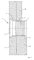
- the punching embossment 1 shown in the drawing is a so-called Mehr Schl.sniet, which is suitable for the joint connection of an upper joining part 2 with a thicker lower joining part 3a or a thinner lower joining part 3b.
- Such a punched embossing rivet offers the possibility of being able to combine different joint thicknesses with a single type of rivet.
- the punch rivet 1 designed as a solid rivet contains a frustoconical rivet head 4 and an adjoining cylindrical shaft 5, in which a plurality of adjoining shaft grooves 6 are arranged. At the lower end of the shaft 5, a sharp edge 7 is provided, by means of which the production of the punched holes in the joining parts 2 and 3a or 3b to be joined is facilitated.
- this punched embossing rivet 1 is pressed from top to bottom by a riveting punch (not shown) through the joining parts 2 and 3a or 3b fixed by means of a hold-down, wherein punched holes aligned with one another are produced in the joining parts.
- a riveting punch not shown
- an annular recess 8 is embossed into the lower joining part 3a or 3b with the aid of a corresponding die around the shaft 5, thereby causing the material of the lower joining part 3a or 3b to be pressed into the shaft grooves 6 under plastic deformation will and will fill this.
- the stamped embossment 1 consists of a zirconia-reinforced alumina ceramic with a zirconium oxide content of more than 60% by weight and a material density of more than 5.2 kg / dm 3 .
- the invention is not limited to the Mehr Anlagensniet shown in the drawing and described in detail.
- the grooves can also run over the entire shaft.
- the stamped embossment can also have only one shank groove.
- the shank groove instead of the notch shape may also be rounded or trapezoidal.
Landscapes
- Engineering & Computer Science (AREA)
- Chemical & Material Sciences (AREA)
- General Engineering & Computer Science (AREA)
- Mechanical Engineering (AREA)
- Composite Materials (AREA)
- Ceramic Engineering (AREA)
- Manufacturing & Machinery (AREA)
- Materials Engineering (AREA)
- Structural Engineering (AREA)
- Organic Chemistry (AREA)
- Insertion Pins And Rivets (AREA)
- Connection Of Plates (AREA)
Description
Die Erfindung betrifft einen Stanz-Prägeniet nach dem Oberbegriff des Anspruchs 1.The invention relates to a stamped embossing rivet according to the preamble of claim 1.
Derartige Stanz-Prägeniete werden zur Verbindung von zwei oder mehreren Fügeteilen, Halbzeugarten, Blechen, Profilen und dgl. verwendet. Dabei wird der Niet zunächst mit Hilfe eines Nietstempels ohne Vorlochen durch die zu verbindenden Fügeteile gedrückt, wobei der Niet gleichzeitig als Schneidstempel fungiert. Nach Erreichen eines Anschlagpunktes des Nietstempels werden die zu verbindenden Fügeteile mit der nun geschlossen Fläche von Nietstempel und Niederhalter gegen eine untere Matrize gedrückt. Dadurch wird in das untere Fügeteil um das Schaftende des Niets herum eine Ringnut geprägt, wodurch der Werkstoff des unteren Fügeteils in mindestens eine umlaufende Schaftnut des Nietes gedrückt wird.Such punching embossing rivets are used to join two or more parts to be joined, semi-finished products, sheets, profiles and the like. The rivet is first pressed by means of a Nietstempels without pre-punching through the joining parts to be joined, the rivet also acts as a cutting punch. After reaching a stop point of the riveting punch, the joining parts to be joined are pressed against a lower die with the now closed surface of riveting punch and hold-down. As a result, an annular groove is embossed in the lower joining part around the shank end of the rivet, as a result of which the material of the lower joining part is pressed into at least one circumferential shank groove of the rivet.
Die bisher verwendeten Stanz-Prägeniete sind üblicherweise aus Stahl hergestellt. Bei der Verbindung von Werkstoffen, die in der Kombination mit Stahl-Verbindungselementen zu Korrosion neigen, können jedoch Probleme in Bezug auf die Korrosion zwischen dem Stanzniet und den zu verbindenden Fügeteilen auftreten. Solche Niete sind aus Dokument EP 1 054 169 bekannt, des ein Stanz-Prägeniet gemäß dem Oberbegriff des Anspruchs 1 offenbart. Daher sind die Niete in der Regel mit einer Korrosionsschutzschicht versehen. Beim Einstanzen der Niete in die Fügeteile kann diese Korrosionsschutzschicht jedoch wieder teilweise zerstört werden, wodurch der Korrosionsschutz nicht mehr in gewünschter Weise gewährleistet ist. Darüber hinaus ist kaum eine Beschichtung für den Einsatz in Magnesium geeignet. Probleme gibt es auch bei der mechanischen Nachbearbeitung an der Nietstelle durch Schleifen. Hierbei wird der Korrosionsschutz des Niets ebenfalls beschädigt und das Bauteil kann korrodieren.The previously used punched embossing rivets are usually made of steel. When joining materials that tend to corrode when combined with steel fasteners, however, corrosion problems may occur between the punch rivet and the adherends to be joined. Such rivets are known from document EP 1 054 169, which discloses a stamped embossing rivet according to the preamble of claim 1. Therefore, the rivets are usually provided with a corrosion protection layer. When punching the rivets in the parts to be joined, however, this corrosion protection layer can be partially destroyed again, whereby the corrosion protection is no longer guaranteed in the desired manner. In addition, hardly any coating is suitable for use in magnesium. There are also problems with mechanical post-processing at the riveting point due to grinding. In this case, the corrosion protection of the rivet is also damaged and the component can corrode.
Aufgabe der Erfindung ist es, einen Stanz-Prägeniet der eingangs genannten Art zu schaffen, der die vorgenannten Probleme beseitigt.The object of the invention is to provide a stamped embossing rivet of the type mentioned, which eliminates the aforementioned problems.
Diese Aufgabe wird durch einen Stanz-Prägeniet mit den Merkmalen des Anspruches 1 gelöst. Vorteilhafte Ausgestaltungen und zweckmäßige Weiterbildungen der Erfindung sind den Unteransprüchen entnehmbar.This object is achieved by a stamped embossing rivet with the features of claim 1. Advantageous embodiments and expedient developments of the invention are the dependent claims.
Der erfindungsgemäße Stanz-Prägeniet ist aus einem druck- und scherfesten Keramikmaterial hergestellt. Die Nietgeometrie wird z.B. im Spritzgießverfahren erzeugt. Durch eine Wärmebehandlung nach der Formgebung bekommt der Niet seine Härte. Wie bei Anwendungen mit einem Vollniet aus Stahl wird der Keramikniet selbststanzend durch die Fügeteillagen gedrückt ohne dabei zerstört zu werden.The punch embossing rivet according to the invention is made of a pressure and shear resistant ceramic material. The rivet geometry is e.g. produced by injection molding. By a heat treatment after molding, the rivet gets its hardness. As with applications with a solid rivet made of steel, the ceramic rivet is self-piercing pressed through the joining sections without being destroyed.
Zwischen dem Keramikniet und dem Fügeteilwerkstoff entsteht kein elektrochemisches Potential. Der nichtleitende Werkstoff Keramik verhindert damit eine elektrochemische Korrosion. Der aus Keramik bestehende Niet kann auch z.B. durch Schleifen mechanisch bearbeitet werden.There is no electrochemical potential between the ceramic rivet and the joining part material. The non-conductive material ceramic thus prevents electrochemical corrosion. The ceramic rivet may also be made e.g. be mechanically processed by grinding.
Der Stanz-Prägeniet besteht bevorzugt aus einer Oxidkeramik, Nichtoxidkeramik oder Mischungen verschiedener Oxidkeramiken sowie Mischungen von Nichtoxidkeramiken. Als besonders geeignetes Keramikmaterial für einen Stanz-Prägeniet hat sich eine Zirkonoxidverstärkte Aluminiumoxid- Keramik mit einem Zirkonoxidanteil von mehr als 60 Gewichts- % und einer Werkstoffdichte von mehr als 5,2 kg/dm3 herausgestellt. Der Stanz-Prägeniet weist in vorteilhafter Weise eine Druckfestigkeit von mehr als 2900 N/mm2, eine Biegefestigkeit von mehr als 700 N/mm2 , eine Bruchzähigkeit von mehr als 8 KIC und ein E-Modul von weniger als 270 N/mm2 auf. Die Härte des Stanz-Prägeniets sollte kleiner als 1900 HV 10 (Härte Vickers) sein. Der Keramikwerkstoff ist ferner gasdicht und säurefest.The stamped embossment preferably consists of an oxide ceramic, non-oxide ceramic or mixtures of various oxide ceramics and mixtures of non-oxide ceramics. A particularly suitable ceramic material for a stamped embossment has been found to be a zirconia-reinforced alumina ceramic having a zirconium oxide content of more than 60% by weight and a material density of more than 5.2 kg / dm 3 . The stamped embossment advantageously has a compressive strength of more than 2900 N / mm 2 , a bending strength of more than 700 N / mm 2 , a fracture toughness of more than 8 K IC and an E-modulus of less than 270 N / mm 2 on. The hardness of the punching embossment should be less than 1900 HV 10 (Vickers hardness). The ceramic material is also gas-tight and acid-resistant.
Weitere Besonderheiten und Vorzüge der Erfindung ergeben sich aus der folgenden Beschreibung eines Ausführungsbeispiels anhand der Zeichnung, die einen sogenannten Mehrbereichsniet zur Verbindung von Werkstücken mit unterschiedlicher Fügeteildicke zeigt.Other features and advantages of the invention will become apparent from the following description of an embodiment with reference to the drawing, which shows a so-called Mehrbereichsniet for connecting workpieces with different joint thickness.
Der in der Zeichnung dargestellte Stanz-Prägeniet 1 ist ein sogenannter Mehrbereichsniet, der zur Fügeverbindung eines oberen Fügeteils 2 mit einem dickeren unteren Fügeteil 3a oder einem dünneren unteren Fügeteil 3b geeignet ist. Ein derartiger Stanz-Prägeniet bietet die Möglichkeit, unterschiedliche Fügeteildicken mit einen einzigen Niettyp verbinden zu können. Der als Vollniet ausgeführte Stanz-Prägeniet 1 enthält einen kegelstumpfförmigen Nietkopf 4 und einen daran anschließenden zylindrischen Schaft 5, in dem mehrere aneinanderliegende Schaftnuten 6 angeordnet sind. Am unteren Ende des Schafts 5 ist eine scharfe Kante 7 vorgesehen, durch welche die Herstellung der Stanzlöcher in den zu verbindenden Fügeteilen 2 und 3a bzw. 3b erleichtert wird.The punching embossment 1 shown in the drawing is a so-called Mehrbereichsniet, which is suitable for the joint connection of an upper joining part 2 with a thicker lower joining
Zum Herstellen einer Nietverbindung wird dieser Stanz-Prägeniet 1 durch einen nicht gezeigten Nietstempel von oben nach unten durch die mittels eines Niederhalters fixierten Fügeteile 2 und 3a bzw. 3b gedrückt, wobei in den Fügeteilen miteinander fluchtende Stanzlöcher entstehen. Nach Beendigung des Stanzvorgangs wird in das untere Fügeteil 3a bzw. 3b mit Hilfe einer entsprechenden Matrize um den Schaft 5 herum eine ringförmige Vertiefung 8 geprägt, wodurch bewirkt wird, das Material des unteren Fügeteils 3a bzw. 3b unter plastischer Deformation in die Schaftnuten 6 gedrückt wird und diese ausfüllt.To produce a riveted joint, this punched embossing rivet 1 is pressed from top to bottom by a riveting punch (not shown) through the joining
Der Stanz-Prägeniet 1 besteht aus einer Zirkonoxidverstärkten Aluminiumoxid - Keramik mit einem Zirkonoxidanteil von mehr als 60 Gewichts-% und einer Werkstoffdichte von mehr als 5,2 kg/dm3.The stamped embossment 1 consists of a zirconia-reinforced alumina ceramic with a zirconium oxide content of more than 60% by weight and a material density of more than 5.2 kg / dm 3 .
Die Erfindung ist nicht auf den in der Zeichnung dargestellten und im einzelnen beschriebenen Mehrbereichsniet beschränkt. Die Nuten können auch über den gesamten Schaft verlaufen. Der Stanz-Prägeniet kann auch nur eine Schaftnut aufweisen. Darüber hinaus kann die Schaftnut anstelle der Kerbform auch abgerundet oder trapezförmig ausgebildet sein.The invention is not limited to the Mehrbereichsniet shown in the drawing and described in detail. The grooves can also run over the entire shaft. The stamped embossment can also have only one shank groove. In addition, the shank groove instead of the notch shape may also be rounded or trapezoidal.
Claims (8)
- Punched/stamped rivet (1) with a rivet head (4) and an adjoining shank (5) for punching through at least two superposed joint parts (2, 3a, 3b), the shank (5) comprising at least one shank groove (6) for filling with material at least of the lower part of the joint (3a, 3b) in the punching direction during an immediately following stamping operation, characterised in that the entire punched/stamped rivet (1) is made of an aluminium oxide ceramic material reinforced with zirconium oxide.
- Punched/stamped rivet according to claim 1, characterised in that the aluminium oxide ceramic material reinforced with zirconium oxide has a zirconium oxide content of more than 60% by weight and a material density of more than 5.2 kg/dm3.
- Punched/stamped rivet according to claim 1 or 2, characterised in that it has a compression strength of more than 2900 N/mm2.
- Punched/stamped rivet according to one of claims 1 to 3, characterised in that it has a bending strength of more than 700 N/mm2.
- Punched/stamped rivet according to one of claims 1 to 4, characterised in that it has a fracture strength of more than 8 KIC.
- Punched/stamped rivet according to one of claims 1 to 5, characterised in that it has an E modulus of less than 270 Nmm2.
- Punched/stamped rivet according to one of claims 1 to 6, characterised in that it has a hardness of less than 1900 HV 10.
- Punched/stamped rivet according to one of claims 1 to 7, characterised in that the ceramic material is gas tight and acid resistant.
Applications Claiming Priority (3)
| Application Number | Priority Date | Filing Date | Title |
|---|---|---|---|
| DE10301114A DE10301114A1 (en) | 2003-01-14 | 2003-01-14 | Punching rivet |
| DE10301114 | 2003-01-14 | ||
| PCT/EP2003/013756 WO2004063575A1 (en) | 2003-01-14 | 2003-12-05 | Punched/stamped rivet |
Publications (2)
| Publication Number | Publication Date |
|---|---|
| EP1588062A1 EP1588062A1 (en) | 2005-10-26 |
| EP1588062B1 true EP1588062B1 (en) | 2006-11-22 |
Family
ID=32519952
Family Applications (1)
| Application Number | Title | Priority Date | Filing Date |
|---|---|---|---|
| EP03782312A Expired - Lifetime EP1588062B1 (en) | 2003-01-14 | 2003-12-05 | Punched/stamped rivet |
Country Status (10)
| Country | Link |
|---|---|
| US (1) | US20050281632A1 (en) |
| EP (1) | EP1588062B1 (en) |
| JP (1) | JP2006513377A (en) |
| CN (1) | CN1738977A (en) |
| AU (1) | AU2003289966A1 (en) |
| BR (1) | BR0317960A (en) |
| CA (1) | CA2512739C (en) |
| DE (2) | DE10301114A1 (en) |
| ES (1) | ES2275128T3 (en) |
| WO (1) | WO2004063575A1 (en) |
Families Citing this family (7)
| Publication number | Priority date | Publication date | Assignee | Title |
|---|---|---|---|---|
| US7966709B2 (en) * | 2007-06-14 | 2011-06-28 | Meyer Intellectual Properties Limited | Cookware article with internally flush rivets |
| ES2536666T3 (en) | 2010-01-27 | 2015-05-27 | Tox Pressotechnik Gmbh & Co. Kg | Connecting element and method for manufacturing a connecting element |
| CN102141069A (en) * | 2011-03-23 | 2011-08-03 | 苏州工业园区新凯精密五金有限公司 | Solid self-punching rivet |
| US9174263B2 (en) | 2012-05-23 | 2015-11-03 | Temper Ip, Llc | Tool and shell using induction heating |
| US9555580B1 (en) | 2013-03-21 | 2017-01-31 | Temper Ip, Llc. | Friction stir welding fastener |
| US9656317B1 (en) | 2014-02-03 | 2017-05-23 | Temper Ip, Llc | Stamp, mold, quench of aluminum and magnesium sheet |
| CN108311627A (en) * | 2017-01-16 | 2018-07-24 | 泛亚汽车技术中心有限公司 | Puncture steel nail and its installation mold certainly for connecting metallic plate |
Family Cites Families (14)
| Publication number | Priority date | Publication date | Assignee | Title |
|---|---|---|---|---|
| GB1471666A (en) * | 1973-07-19 | 1977-04-27 | Ocean Investments Ltd | Method and fastener for use in joining together an assembly of metal sheets |
| US4018023A (en) * | 1974-03-06 | 1977-04-19 | The Carborundum Company | Ceramic elements and insulation assembly including such elements |
| US4414011A (en) * | 1982-05-25 | 1983-11-08 | United Technologies Corporation | Method of securing fiber reinforced glass matrix composite material to structural members |
| US4810150A (en) * | 1984-06-26 | 1989-03-07 | Toshiba Monofrax Company, Ltd. | Ceramic fiber layer fixing pin |
| US4978270A (en) * | 1987-07-31 | 1990-12-18 | Akh, Inc. | Headless rivet |
| US5046141A (en) * | 1988-02-10 | 1991-09-03 | Compaq Computer Corporation | Low conductivity mounting stud and a method and apparatus for fastening an electronic component using the same |
| US5007781A (en) * | 1990-09-10 | 1991-04-16 | General Dynamics Corporation, Convair Division | Tapered split-bushing fastener |
| US5332271A (en) * | 1991-10-02 | 1994-07-26 | Grant Robert W | High temperature ceramic nut |
| DE19536982A1 (en) * | 1995-10-04 | 1997-04-17 | Deutsche Forsch Luft Raumfahrt | Method and device for transmitting forces between two joining parts |
| DE19734147C2 (en) * | 1997-08-07 | 2003-06-26 | Daimler Chrysler Ag | A connection between components |
| JPH11270523A (en) * | 1998-03-25 | 1999-10-05 | Ikusuke Yoshimura | Fastening pin and its fastening structure |
| DE29908928U1 (en) * | 1999-05-21 | 2000-10-05 | Kerb-Konus-Vertriebs-GmbH, 92224 Amberg | Stamped embossed rivet |
| US6514593B1 (en) * | 1999-08-23 | 2003-02-04 | Northrop Grumman Corporation | Mechanically locking Z-pins |
| US7008157B2 (en) * | 2001-06-21 | 2006-03-07 | Black & Decker Inc. | Explosive assisted expanding fastener |
-
2003
- 2003-01-14 DE DE10301114A patent/DE10301114A1/en not_active Withdrawn
- 2003-12-05 CN CN200380108798.1A patent/CN1738977A/en active Pending
- 2003-12-05 ES ES03782312T patent/ES2275128T3/en not_active Expired - Lifetime
- 2003-12-05 AU AU2003289966A patent/AU2003289966A1/en not_active Abandoned
- 2003-12-05 BR BR0317960-5A patent/BR0317960A/en not_active IP Right Cessation
- 2003-12-05 WO PCT/EP2003/013756 patent/WO2004063575A1/en active IP Right Grant
- 2003-12-05 JP JP2004565956A patent/JP2006513377A/en active Pending
- 2003-12-05 EP EP03782312A patent/EP1588062B1/en not_active Expired - Lifetime
- 2003-12-05 DE DE50305802T patent/DE50305802D1/en not_active Expired - Lifetime
- 2003-12-05 CA CA002512739A patent/CA2512739C/en not_active Expired - Fee Related
-
2005
- 2005-06-29 US US11/170,766 patent/US20050281632A1/en not_active Abandoned
Also Published As
| Publication number | Publication date |
|---|---|
| BR0317960A (en) | 2005-11-29 |
| JP2006513377A (en) | 2006-04-20 |
| CA2512739C (en) | 2009-02-24 |
| CA2512739A1 (en) | 2004-07-29 |
| AU2003289966A1 (en) | 2004-08-10 |
| ES2275128T3 (en) | 2007-06-01 |
| WO2004063575A1 (en) | 2004-07-29 |
| DE50305802D1 (en) | 2007-01-04 |
| US20050281632A1 (en) | 2005-12-22 |
| DE10301114A1 (en) | 2004-07-22 |
| CN1738977A (en) | 2006-02-22 |
| EP1588062A1 (en) | 2005-10-26 |
Similar Documents
| Publication | Publication Date | Title |
|---|---|---|
| EP2314890B1 (en) | Half hollow punch rivet | |
| EP3371467B1 (en) | Semi-hollow self-piercing rivet for thin sheet metal joints, method for producing said semi-hollow self-piercing rivet, and method for producing a joint | |
| DE3003908A1 (en) | Studs with punching and riveting behavior | |
| EP1064466B1 (en) | Punching rivet | |
| DE10060421C2 (en) | Fixed rivet made of an aluminum alloy | |
| DE2720924A1 (en) | FLAP CONNECTION FOR FIXED MUTUAL CONNECTING OF PANEL PIECES AND METHOD FOR PRODUCING SUCH A FLAP CONNECTION | |
| WO2017063859A1 (en) | Arrangement for connecting two vehicle body components and method for producing a sheet metal component having a doubled joining flange | |
| EP1588062B1 (en) | Punched/stamped rivet | |
| EP0934132B1 (en) | Diffusion welding process and device for joining sheet metal parts | |
| WO2015022161A1 (en) | Semi-tubular punch rivet for pre-punchless joining of a fiber composite component to a metal component | |
| DE1925461A1 (en) | Process for the production of metal plate links for articulated plate conveyors | |
| DE112012000353B4 (en) | rivet connection | |
| EP2886218B1 (en) | Method for punching holes in a multi-layer sheet metal | |
| DE102008016273B4 (en) | Method for connecting a functional element with a metal sheet and connection between a metal sheet and a functional element | |
| DE102012022504A1 (en) | Press connection device of components, has surface structure that is formed only in region of associated connecting surface of corresponding component | |
| DE102009052879A1 (en) | Punching rivet | |
| DE19927101A1 (en) | Mechanical joining by clinch process involves punch and pressure pad and top and bottom stops to control pad movement and upset material neck region. | |
| DE102015000982B4 (en) | Method for connecting several flat components and component arrangement | |
| DE20300533U1 (en) | Rivet for joining sheet material has peripheral grooves which fill with material of sheets when it is driven through them, rivet being made from ceramic | |
| DE2138189B2 (en) | DIE FOR THE DEFORMING OF METALS | |
| EP1900452B1 (en) | Method for reinforcing a wall of a three dimensional fitting | |
| DE102017208274A1 (en) | Method for producing a component with integrated joining auxiliary element and semifinished product | |
| WO2008055475A1 (en) | Riveted joint | |
| DE1910377C3 (en) | Plate riveted connection | |
| DE10134963C2 (en) | Rivet, in particular high-strength rivet, production of the rivet and a rivet connection using the rivet |
Legal Events
| Date | Code | Title | Description |
|---|---|---|---|
| PUAI | Public reference made under article 153(3) epc to a published international application that has entered the european phase |
Free format text: ORIGINAL CODE: 0009012 |
|
| 17P | Request for examination filed |
Effective date: 20050816 |
|
| AK | Designated contracting states |
Kind code of ref document: A1 Designated state(s): AT BE BG CH CY CZ DE DK EE ES FI FR GB GR HU IE IT LI LU MC NL PT RO SE SI SK TR |
|
| AX | Request for extension of the european patent |
Extension state: AL LT LV MK |
|
| DAX | Request for extension of the european patent (deleted) | ||
| RBV | Designated contracting states (corrected) |
Designated state(s): DE ES FR GB IT SE |
|
| GRAP | Despatch of communication of intention to grant a patent |
Free format text: ORIGINAL CODE: EPIDOSNIGR1 |
|
| GRAS | Grant fee paid |
Free format text: ORIGINAL CODE: EPIDOSNIGR3 |
|
| GRAA | (expected) grant |
Free format text: ORIGINAL CODE: 0009210 |
|
| AK | Designated contracting states |
Kind code of ref document: B1 Designated state(s): DE ES FR GB IT SE |
|
| REG | Reference to a national code |
Ref country code: GB Ref legal event code: FG4D Free format text: NOT ENGLISH |
|
| GBT | Gb: translation of ep patent filed (gb section 77(6)(a)/1977) |
Effective date: 20061122 |
|
| REF | Corresponds to: |
Ref document number: 50305802 Country of ref document: DE Date of ref document: 20070104 Kind code of ref document: P |
|
| REG | Reference to a national code |
Ref country code: SE Ref legal event code: TRGR |
|
| ET | Fr: translation filed | ||
| REG | Reference to a national code |
Ref country code: ES Ref legal event code: FG2A Ref document number: 2275128 Country of ref document: ES Kind code of ref document: T3 |
|
| PLBE | No opposition filed within time limit |
Free format text: ORIGINAL CODE: 0009261 |
|
| STAA | Information on the status of an ep patent application or granted ep patent |
Free format text: STATUS: NO OPPOSITION FILED WITHIN TIME LIMIT |
|
| 26N | No opposition filed |
Effective date: 20070823 |
|
| PGFP | Annual fee paid to national office [announced via postgrant information from national office to epo] |
Ref country code: SE Payment date: 20111231 Year of fee payment: 9 |
|
| PG25 | Lapsed in a contracting state [announced via postgrant information from national office to epo] |
Ref country code: SE Free format text: LAPSE BECAUSE OF NON-PAYMENT OF DUE FEES Effective date: 20121206 |
|
| REG | Reference to a national code |
Ref country code: FR Ref legal event code: PLFP Year of fee payment: 13 |
|
| REG | Reference to a national code |
Ref country code: FR Ref legal event code: PLFP Year of fee payment: 14 |
|
| REG | Reference to a national code |
Ref country code: FR Ref legal event code: PLFP Year of fee payment: 15 |
|
| PGFP | Annual fee paid to national office [announced via postgrant information from national office to epo] |
Ref country code: GB Payment date: 20201228 Year of fee payment: 18 Ref country code: FR Payment date: 20201229 Year of fee payment: 18 |
|
| PGFP | Annual fee paid to national office [announced via postgrant information from national office to epo] |
Ref country code: IT Payment date: 20201221 Year of fee payment: 18 |
|
| PGFP | Annual fee paid to national office [announced via postgrant information from national office to epo] |
Ref country code: ES Payment date: 20210125 Year of fee payment: 18 Ref country code: DE Payment date: 20201229 Year of fee payment: 18 |
|
| REG | Reference to a national code |
Ref country code: DE Ref legal event code: R119 Ref document number: 50305802 Country of ref document: DE |
|
| GBPC | Gb: european patent ceased through non-payment of renewal fee |
Effective date: 20211205 |
|
| PG25 | Lapsed in a contracting state [announced via postgrant information from national office to epo] |
Ref country code: GB Free format text: LAPSE BECAUSE OF NON-PAYMENT OF DUE FEES Effective date: 20211205 Ref country code: DE Free format text: LAPSE BECAUSE OF NON-PAYMENT OF DUE FEES Effective date: 20220701 |
|
| PG25 | Lapsed in a contracting state [announced via postgrant information from national office to epo] |
Ref country code: FR Free format text: LAPSE BECAUSE OF NON-PAYMENT OF DUE FEES Effective date: 20211231 |
|
| PG25 | Lapsed in a contracting state [announced via postgrant information from national office to epo] |
Ref country code: IT Free format text: LAPSE BECAUSE OF NON-PAYMENT OF DUE FEES Effective date: 20211205 |
|
| REG | Reference to a national code |
Ref country code: ES Ref legal event code: FD2A Effective date: 20230215 |
|
| PG25 | Lapsed in a contracting state [announced via postgrant information from national office to epo] |
Ref country code: ES Free format text: LAPSE BECAUSE OF NON-PAYMENT OF DUE FEES Effective date: 20211206 |