EP1587990B1 - Vorrichtung für in leitplanken entlang strassen verwendetes drahtseil - Google Patents
Vorrichtung für in leitplanken entlang strassen verwendetes drahtseil Download PDFInfo
- Publication number
- EP1587990B1 EP1587990B1 EP04706406A EP04706406A EP1587990B1 EP 1587990 B1 EP1587990 B1 EP 1587990B1 EP 04706406 A EP04706406 A EP 04706406A EP 04706406 A EP04706406 A EP 04706406A EP 1587990 B1 EP1587990 B1 EP 1587990B1
- Authority
- EP
- European Patent Office
- Prior art keywords
- arrangement
- component
- aforementioned
- accordance
- clamping
- Prior art date
- Legal status (The legal status is an assumption and is not a legal conclusion. Google has not performed a legal analysis and makes no representation as to the accuracy of the status listed.)
- Expired - Lifetime
Links
Images


Classifications
-
- E—FIXED CONSTRUCTIONS
- E01—CONSTRUCTION OF ROADS, RAILWAYS, OR BRIDGES
- E01F—ADDITIONAL WORK, SUCH AS EQUIPPING ROADS OR THE CONSTRUCTION OF PLATFORMS, HELICOPTER LANDING STAGES, SIGNS, SNOW FENCES, OR THE LIKE
- E01F15/00—Safety arrangements for slowing, redirecting or stopping errant vehicles, e.g. guard posts or bollards; Arrangements for reducing damage to roadside structures due to vehicular impact
- E01F15/02—Continuous barriers extending along roads or between traffic lanes
- E01F15/06—Continuous barriers extending along roads or between traffic lanes essentially made of cables, nettings or the like
Definitions
- the present invention relates to an arrangement for splicing of wire cables used in crash barriers along roads which are intended to extend along the side of a carriageway and are supported by uprights distributed along the aforementioned carriageway, in that an external conical clamping component, which is arranged divided in its longitudinal sense and exhibits an internally transcurrent hole with an internal thread, is so arranged as to be capable of being connected to a cable made of metal in that the end of a respective metal cable of the kind in question is so arranged as to be accommodated in an aforementioned clamping component, and in that the aforementioned external conical clamping component is capable of being accommodated in an internally conical splicing sleeve.
- Previously disclosed arrangements for causing the splicing of cables made of steel that are intended to provide protection for traffic on roads comprise splicing means which require expensive equipment at the site of erection of the cables, for example in the form of presses to bring about connection of a tubular sleeve to the end of a cable with the help of a press of this kind which costs ca. one hundred thousand kronor, for example such a press which brings about such clamping of the tubular sleeve around the cable and is illustrated in Fig. 13 .
- the splicing arrangement previously disclosed through US 2,180,866A comprises a common splicing sleeve (1). Rotation of the aforementioned splicing sleeve causes the clamping effect to be identical at both of its ends. Separate actuation of the respective clamping component is thus not permitted in the aforementioned previously disclosed arrangement, but both pairs of clamping components (5, 6) are actuated jointly by the aforementioned splicing sleeve (1).
- the principal object of the present invention is thus, in the first instance, to solve the above-mentioned problem by simple and efficient means and to bring about the secure splicing of cables without the need to use expensive special machines and tools for this purpose.
- the aforementioned object is achieved by means of an arrangement in accordance with the present claim 1.
- the clamping components are each connected together with an interconnecting component or an,interconnecting holding stop via its own threaded rod or via its own pair of threaded rods, which threaded rods are connected to one another with the common interconnecting component or the common interconnecting stop.
- the so-called central crash barrier is normally erected in the form of steel cables between the carriageways on roads of a kind which are hazardous due to oncoming traffic, or where the decision has not yet been taken to widen the road into a motorway, although crash barriers of this kind are also erected between motorway carriageways which lie close to one another and in order to prevent vehicles from ending up on oncoming carriageways when overtaking or in the event of accidents involving leaving the road.
- crash barriers of this kind are also erected between motorway carriageways which lie close to one another and in order to prevent vehicles from ending up on oncoming carriageways when overtaking or in the event of accidents involving leaving the road.
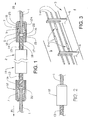
- the aforementioned cables 1, which are intended to extend along the side 3 of a carriageway 4,5 of the kind in question, supported by a number of uprights 6 distributed along the carriageway 4, 5 and anchored to the ground, are preferably in the form of strong steel cables 1, as shown in Fig. 9 as the preferred illustrative example.
- a splicing arrangement 2 of this kind is formed by an externally conical clamping component 7, which is so arranged as to be divided into the desired number of parts 7A, 7B, 7C in its longitudinal sense 8 and which exhibits an internally transcurrent hole 9 which is provided with an internal thread 10.
- the aforementioned clamping component 7 is so arranged as to be capable of being connected to a cable 1 of the kind in question made of metal, in that one end 11 of the respective cable 1 is so arranged as to be capable of being accommodated in an aforementioned clamping component 7.
- the aforementioned externally conical clamping component 7 is so arranged as to be capable of being accommodated in a splicing sleeve 12 that is internally conical at one end 12A.
- the aforementioned clamping arrangement 2 comprises a threaded bar 13, which is capable of being connected with an attachment component 14 that is also provided with a thread 15, 16.
- the aforementioned attachment component 14 is capable of being screwed securely with its external thread 16 to an internal thread 17 in each splicing sleeve 12.
- a common interconnecting component 19 containing threads and capable of being connected to the threads 18 in the respective rod 13 is so arranged as to connect the cables 1, which extend in a direction from one another 20, 21, to one another via clamping components 7 and attachment components 14.
- interacting stop components 22 which can be formed by a number of pins projecting axially from the aforementioned connecting component 14 and/or attachment component 7, a ring or some similar pressure device integrated with the respective attachment component 14.
- a number of pins is preferably arranged distributed around the periphery of the aforementioned attachment component 14 and/or the clamping component 7.
- the threaded rod 13 can be caused to press directly against the free end 1A of the cable, so that this is forced securely into the clamping component 13, which in turn is clamped in the splicing sleeve.
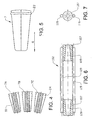
- the aforementioned clamping component 7 is in three parts in the illustrated example, and the aforementioned parts 7A, 7B, 7C are so arranged as to be held together by an all-round annular element 23, such as an o-ring, which is accommodated in an all-round groove 24 in the aforementioned clamping component 7, which can naturally consist of a different number of components than the aforementioned three.
- the clamping component 7 also exhibits an internal fine thread 10, preferably an M18 x 1.5 thread, so that the grip on a cable 1 is strong and the cable is retained in the desired grip in the clamping component 7 when it is caused to move axially 20, 21 into the conical part 25 of the clamping component 7.
- the splicing sleeve 12 is manufactured so that it is formed preferably from stainless steel or hot-dip galvanized steel.
- the clamping component 7 can be executed from carbon steel, for instance.
- the conical splicing sleeves 12 are first introduced onto the respective end of the cable so that the end of the cable and the splicing sleeve are situated axially more or less on the same level as one another.
- the clamping components 7 are then introduced onto the ends of the cables and engage with them so that the keyed joint enters into effect.
- the next stage involves drawing the cable connections towards one another, for example with the help of a hydraulic jack, using the force at which the cables will subsequently be pre-tensioned.
- the clamping component 14 with the interacting stop components 22 is then.screwed onto the respective splicing sleeve, after which the attachment component is tightened, for example with the help of key holes on the flat surface of the attachment component.
- the threaded rods 13 are screwed onto the respective attachment component.
- the two threaded rods are connected to the common interconnection component 19, after which the applied force is released.
- the splicing arrangement 102 illustrated in Figs. 6-8 functions in a different fashion to the splicing arrangement 2 described above and is not a part of the invention. Pairs of round bars 119 then adopt the function of an interconnecting component, and each of these is securely attached to its own internal clamping component 107, in the inner conical cavity 109 of which an end 101 of a cable is capable of being accommodated and so arranged as to be securely clamped.
- Told arrangement 102 which does not form part of the invention but represents background art, is useful for better understanding of the invention.
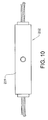
- Fig. 10 illustrates a larger splicing arrangement 202, in which the inside of its external tube 219 exhibits right-hand and left-hand threads, and where its keyed joint is externally threaded.
- FIG. 11 Illustrated in Fig. 11 is a variant of the splicing arrangement 302, in which each of the cables 301 enters its own clamping component 307, 312, whereby each of these is connected via its own pair of threaded rods 350, 351 to an interconnection stop 352 via its matching holes 353.
- Each threaded rod 350, 351 is so arranged by means of its own nut 354 as to be capable of being drawn into the respective hole 353 when the nuts are tightened.
- the clamping components 307, 312 can then be introduced in the direction of the arrows 375, 376, so that the cables are tensioned.
- Fig. 13 illustrates the function of an ordinary method of splicing cables with the help of a tube or a sleeve pressed or rolled onto the end of the cable.
- This method calls for expensive equipment, however, in order to be able to press the associated tube/sleeve with a threaded bar securely onto the cable. equivalent technology, without departing from the area of protection afforded to the invention, as defined in the patent Claims.
Landscapes
- Engineering & Computer Science (AREA)
- Aviation & Aerospace Engineering (AREA)
- Architecture (AREA)
- Civil Engineering (AREA)
- Structural Engineering (AREA)
- Bridges Or Land Bridges (AREA)
- Laying Of Electric Cables Or Lines Outside (AREA)
- Refuge Islands, Traffic Blockers, Or Guard Fence (AREA)
- Mutual Connection Of Rods And Tubes (AREA)
- Clamps And Clips (AREA)
- Investigating Or Analyzing Materials By The Use Of Electric Means (AREA)
- Apparatus For Radiation Diagnosis (AREA)
- Semiconductor Memories (AREA)
- Amplifiers (AREA)
- Silver Salt Photography Or Processing Solution Therefor (AREA)
- Platform Screen Doors And Railroad Systems (AREA)
Claims (10)
- Anordnung (1) zum Spleißen von Drahtseilen (1), die in Leitplanken entlang von Straßen verwendet wird, welche sich entlang der Seite (3) einer Fahrbahn (4, 5) erstrecken sollen und durch Pfosten (6) abgestützt sind, die entlang der vorstehend erwähnten Fahrbahn (4, 5) verteilt sind, indem ein außen konisches Klemmbauteil (7), das in seiner Längsrichtung (8) geteilt eingerichtet ist und ein inneres Durchgangsloch (9) mit einem Innengewinde (10) aufweist, derart eingerichtet ist, dass es mit einem aus Metall hergestellten Seil (1) verbunden sein kann, indem das Ende (11) des jeweiligen Metallseils (1) der betreffenden Art derart eingerichtet ist, dass es in einem vorstehend erwähnten Klemmbauteil (7) aufgenommen ist, und indem das vorstehend erwähnte außen konische Klemmbauteil (7) in einer innen konischen Spleißhülse (12) aufgenommen sein kann, dadurch gekennzeichnet, dass die Klemmbauteile (7:307, 312) jeweils mit einem Verbindungsbauteil (19) oder einem Verbindunghalteanschlag (352) über ihren eigenen Gewindestab (13) oder über ihr eigenes Paar Gewindestäbe (350, 351) miteinander verbunden sind, wobei die Gewindestäbe (13:350, 351) mit dem gemeinsamen Verbindungsbauteil (19) oder dem gemeinsamen Verbindungsanschlag (352) miteinander verbunden sind.
- Anordnung nach Patentanspruch 1, dadurch gekennzeichnet, dass ein Befestigungsbauteil (14), das mit Gewinden (15, 16) versehen ist, die mit einem Gewindestab (13) an seinem jeweiligen Ende verbunden sein können, derart eingerichtet ist, dass es sicher an ein Innengewinde (17) in jeder Spleißhülse (12) geschraubt sein kann, und dass ein gemeinsames Verbindungsbauteil (19), das Gewinde enthält und mit den Gewinden (18) in dem jeweiligen Stab (13) verbunden sein kann, derart eingerichtet ist, dass die Seile über Klemmbauteile (7) und Befestigungsbauteile (14) miteinander verbunden sind.
- Anordnung nach dem einen oder anderen der Patentansprüche 1 - 2, dadurch gekennzeichnet, dass wechselwirkende Anschlagbauteile (22) zwischen den Befestigungsbauteilen (14) und den Klemmbauteilen (7) angeordnet sind.
- Anordnung nach Patentanspruch 3, dadurch gekennzeichnet, dass die vorstehend erwähnten Anschlagbauteile in der Form einer Anzahl von Stiften (22), eines Rings oder Ähnlichem vorliegen, die axial (20, 21) von dem vorstehend erwähnten Verbindungsbauteil (14) und/oder Befestigungsbauteil vorstehen und mit selbigem integriert sind.
- Anordnung nach Patentanspruch 4, dadurch gekennzeichnet, dass die Anzahl von Stiften (22) um den Umfang des Befestigungsbauteils (14) und/oder des Klemmbauteils (7) herum verteilt ist.
- Anordnung nach dem einen oder anderen der vorstehenden Patentansprüche, dadurch gekennzeichnet, dass das Klemmbauteil (7) beispielsweise in drei Teile (7A, 7B, 7C) geteilt ist, und derart eingerichtet ist, dass es durch ein vollständig rundes Ringelement (23), wie etwa einen O-Ring, zusammengehalten ist.
- Anordnung nach Patentanspruch 6, dadurch gekennzeichnet, dass das Ringelement (23) in einer vollständig runden Nut (24) in dem vorstehend erwähnten Klemmbauteil (7) aufgenommen ist.
- Anordnung nach dem einen oder anderen der vorstehenden Patentansprüche, dadurch gekennzeichnet, dass das Klemmbauteil (7) ein inneres Feingewinde (10) aufweist.
- Anordnung nach Patentanspruch 8, dadurch gekennzeichnet, dass das Gewinde (10) in der Form eines M18 x 1,5-Gewindes vorliegt.
- Anordnung nach dem einen oder anderen der Patentansprüche 1 - 9, dadurch gekennzeichnet, dass die Spleißhülse (12) aus rostfreiem oder feuerverzinktem Stahl gebildet ist.
Applications Claiming Priority (3)
| Application Number | Priority Date | Filing Date | Title |
|---|---|---|---|
| SE0300209A SE525404C2 (sv) | 2003-01-29 | 2003-01-29 | Anordning för vägräckslinor |
| SE0300209 | 2003-01-29 | ||
| PCT/SE2004/000112 WO2004067851A1 (en) | 2003-01-29 | 2004-01-29 | Device for wire cable used in crash barries along roads |
Publications (2)
| Publication Number | Publication Date |
|---|---|
| EP1587990A1 EP1587990A1 (de) | 2005-10-26 |
| EP1587990B1 true EP1587990B1 (de) | 2010-05-05 |
Family
ID=20290234
Family Applications (1)
| Application Number | Title | Priority Date | Filing Date |
|---|---|---|---|
| EP04706406A Expired - Lifetime EP1587990B1 (de) | 2003-01-29 | 2004-01-29 | Vorrichtung für in leitplanken entlang strassen verwendetes drahtseil |
Country Status (5)
| Country | Link |
|---|---|
| EP (1) | EP1587990B1 (de) |
| AT (1) | ATE467000T1 (de) |
| DE (1) | DE602004026994D1 (de) |
| SE (1) | SE525404C2 (de) |
| WO (1) | WO2004067851A1 (de) |
Cited By (1)
| Publication number | Priority date | Publication date | Assignee | Title |
|---|---|---|---|---|
| RU175102U1 (ru) * | 2017-01-09 | 2017-11-21 | Общество с ограниченной ответственностью "Энергосервис" | Канат для тросового дорожного ограждения |
Families Citing this family (1)
| Publication number | Priority date | Publication date | Assignee | Title |
|---|---|---|---|---|
| US20240044093A1 (en) * | 2022-08-02 | 2024-02-08 | Zachary Wilson | Device and method for use in repairing cable highway guardrails |
Family Cites Families (2)
| Publication number | Priority date | Publication date | Assignee | Title |
|---|---|---|---|---|
| US2180866A (en) * | 1938-07-20 | 1939-11-21 | John A Cryer | Connector |
| US3163904A (en) * | 1963-06-24 | 1965-01-05 | Supreme Products Corp | Strand chucks |
-
2003
- 2003-01-29 SE SE0300209A patent/SE525404C2/sv unknown
-
2004
- 2004-01-29 DE DE602004026994T patent/DE602004026994D1/de not_active Expired - Lifetime
- 2004-01-29 EP EP04706406A patent/EP1587990B1/de not_active Expired - Lifetime
- 2004-01-29 AT AT04706406T patent/ATE467000T1/de not_active IP Right Cessation
- 2004-01-29 WO PCT/SE2004/000112 patent/WO2004067851A1/en not_active Ceased
Cited By (1)
| Publication number | Priority date | Publication date | Assignee | Title |
|---|---|---|---|---|
| RU175102U1 (ru) * | 2017-01-09 | 2017-11-21 | Общество с ограниченной ответственностью "Энергосервис" | Канат для тросового дорожного ограждения |
Also Published As
| Publication number | Publication date |
|---|---|
| SE0300209L (sv) | 2004-07-30 |
| EP1587990A1 (de) | 2005-10-26 |
| SE525404C2 (sv) | 2005-02-15 |
| ATE467000T1 (de) | 2010-05-15 |
| SE0300209D0 (sv) | 2003-01-29 |
| WO2004067851A1 (en) | 2004-08-12 |
| DE602004026994D1 (de) | 2010-06-17 |
Similar Documents
| Publication | Publication Date | Title |
|---|---|---|
| US3381427A (en) | Frangible and expandable assembly for parking meter supports, stanchions, poles and posts | |
| US5474408A (en) | Break-away coupling with spaced weakened sections | |
| EP0960266B1 (de) | Seilanker | |
| US3630474A (en) | Breakaway pole support structure | |
| US6619630B2 (en) | Breakaway support post for highway guardrail end treatments | |
| US6308927B1 (en) | Breakaway sign post connector | |
| EP2663692B1 (de) | Gelenkvorrichtung zur halterung eines schildpfostens | |
| DE2530420A1 (de) | Spannglied | |
| US6055691A (en) | Method of mounting and tensioning a freely tensioned tension member and device for carrying out the method | |
| DE3138807A1 (de) | Freies zugglied, insbesondere schraegseil fuer eine schraegseilbruecke | |
| US4528786A (en) | Low profile break safe breakaway system | |
| EP1587990B1 (de) | Vorrichtung für in leitplanken entlang strassen verwendetes drahtseil | |
| US6884005B1 (en) | Roof support truss | |
| CN112854210A (zh) | 预应力钢绞线用可回收锚具及其安装方法 | |
| CA2744658C (en) | Cable barrier post anchoring device and related method | |
| WO2007084009A1 (en) | Yielding connector for poles and posts | |
| EP1154077B1 (de) | Wieder ausbaubarer Verpressanker | |
| CN214530646U (zh) | 预应力钢绞线用可回收锚具 | |
| KR102162956B1 (ko) | 케이블 교량의 낙뢰보호 케이블 장력 도입방법 | |
| EP2372026A2 (de) | Druckrohr sowie daraus hergestellter Erdanker | |
| CN1279245C (zh) | 支承路边杆柱的连接器 | |
| KR200163598Y1 (ko) | 그라운드앵커의인장재제거용정착제 | |
| JP2007063796A (ja) | 橋梁の拡幅接続構造および接続方法 | |
| EP0697486B1 (de) | Uni-Einsteckhülse zum Befestigen eines Rohrprofils in einer Fussplatte | |
| CN215289762U (zh) | 一种具有抗拉结构的桥梁裂缝加固装置 |
Legal Events
| Date | Code | Title | Description |
|---|---|---|---|
| PUAI | Public reference made under article 153(3) epc to a published international application that has entered the european phase |
Free format text: ORIGINAL CODE: 0009012 |
|
| 17P | Request for examination filed |
Effective date: 20050704 |
|
| AK | Designated contracting states |
Kind code of ref document: A1 Designated state(s): AT BE BG CH CY CZ DE DK EE ES FI FR GB GR HU IE IT LI LU MC NL PT RO SE SI SK TR |
|
| AX | Request for extension of the european patent |
Extension state: AL LT LV MK |
|
| DAX | Request for extension of the european patent (deleted) | ||
| RIN1 | Information on inventor provided before grant (corrected) |
Inventor name: BUNDGAARD, JESPER Inventor name: ALTNER, LARS |
|
| 17Q | First examination report despatched |
Effective date: 20090710 |
|
| GRAP | Despatch of communication of intention to grant a patent |
Free format text: ORIGINAL CODE: EPIDOSNIGR1 |
|
| GRAS | Grant fee paid |
Free format text: ORIGINAL CODE: EPIDOSNIGR3 |
|
| GRAA | (expected) grant |
Free format text: ORIGINAL CODE: 0009210 |
|
| AK | Designated contracting states |
Kind code of ref document: B1 Designated state(s): AT BE BG CH CY CZ DE DK EE ES FI FR GB GR HU IE IT LI LU MC NL PT RO SE SI SK TR |
|
| REG | Reference to a national code |
Ref country code: GB Ref legal event code: FG4D |
|
| REG | Reference to a national code |
Ref country code: CH Ref legal event code: EP |
|
| REG | Reference to a national code |
Ref country code: IE Ref legal event code: FG4D |
|
| REF | Corresponds to: |
Ref document number: 602004026994 Country of ref document: DE Date of ref document: 20100617 Kind code of ref document: P |
|
| REG | Reference to a national code |
Ref country code: NL Ref legal event code: VDEP Effective date: 20100505 |
|
| PG25 | Lapsed in a contracting state [announced via postgrant information from national office to epo] |
Ref country code: NL Free format text: LAPSE BECAUSE OF FAILURE TO SUBMIT A TRANSLATION OF THE DESCRIPTION OR TO PAY THE FEE WITHIN THE PRESCRIBED TIME-LIMIT Effective date: 20100505 Ref country code: ES Free format text: LAPSE BECAUSE OF FAILURE TO SUBMIT A TRANSLATION OF THE DESCRIPTION OR TO PAY THE FEE WITHIN THE PRESCRIBED TIME-LIMIT Effective date: 20100816 Ref country code: SE Free format text: LAPSE BECAUSE OF FAILURE TO SUBMIT A TRANSLATION OF THE DESCRIPTION OR TO PAY THE FEE WITHIN THE PRESCRIBED TIME-LIMIT Effective date: 20100505 |
|
| PG25 | Lapsed in a contracting state [announced via postgrant information from national office to epo] |
Ref country code: AT Free format text: LAPSE BECAUSE OF FAILURE TO SUBMIT A TRANSLATION OF THE DESCRIPTION OR TO PAY THE FEE WITHIN THE PRESCRIBED TIME-LIMIT Effective date: 20100505 Ref country code: FI Free format text: LAPSE BECAUSE OF FAILURE TO SUBMIT A TRANSLATION OF THE DESCRIPTION OR TO PAY THE FEE WITHIN THE PRESCRIBED TIME-LIMIT Effective date: 20100505 Ref country code: SI Free format text: LAPSE BECAUSE OF FAILURE TO SUBMIT A TRANSLATION OF THE DESCRIPTION OR TO PAY THE FEE WITHIN THE PRESCRIBED TIME-LIMIT Effective date: 20100505 |
|
| PG25 | Lapsed in a contracting state [announced via postgrant information from national office to epo] |
Ref country code: GR Free format text: LAPSE BECAUSE OF FAILURE TO SUBMIT A TRANSLATION OF THE DESCRIPTION OR TO PAY THE FEE WITHIN THE PRESCRIBED TIME-LIMIT Effective date: 20100806 Ref country code: CY Free format text: LAPSE BECAUSE OF FAILURE TO SUBMIT A TRANSLATION OF THE DESCRIPTION OR TO PAY THE FEE WITHIN THE PRESCRIBED TIME-LIMIT Effective date: 20100505 |
|
| PG25 | Lapsed in a contracting state [announced via postgrant information from national office to epo] |
Ref country code: PT Free format text: LAPSE BECAUSE OF FAILURE TO SUBMIT A TRANSLATION OF THE DESCRIPTION OR TO PAY THE FEE WITHIN THE PRESCRIBED TIME-LIMIT Effective date: 20100906 Ref country code: EE Free format text: LAPSE BECAUSE OF FAILURE TO SUBMIT A TRANSLATION OF THE DESCRIPTION OR TO PAY THE FEE WITHIN THE PRESCRIBED TIME-LIMIT Effective date: 20100505 Ref country code: DK Free format text: LAPSE BECAUSE OF FAILURE TO SUBMIT A TRANSLATION OF THE DESCRIPTION OR TO PAY THE FEE WITHIN THE PRESCRIBED TIME-LIMIT Effective date: 20100505 |
|
| PG25 | Lapsed in a contracting state [announced via postgrant information from national office to epo] |
Ref country code: BE Free format text: LAPSE BECAUSE OF FAILURE TO SUBMIT A TRANSLATION OF THE DESCRIPTION OR TO PAY THE FEE WITHIN THE PRESCRIBED TIME-LIMIT Effective date: 20100505 Ref country code: CZ Free format text: LAPSE BECAUSE OF FAILURE TO SUBMIT A TRANSLATION OF THE DESCRIPTION OR TO PAY THE FEE WITHIN THE PRESCRIBED TIME-LIMIT Effective date: 20100505 Ref country code: RO Free format text: LAPSE BECAUSE OF FAILURE TO SUBMIT A TRANSLATION OF THE DESCRIPTION OR TO PAY THE FEE WITHIN THE PRESCRIBED TIME-LIMIT Effective date: 20100505 Ref country code: SK Free format text: LAPSE BECAUSE OF FAILURE TO SUBMIT A TRANSLATION OF THE DESCRIPTION OR TO PAY THE FEE WITHIN THE PRESCRIBED TIME-LIMIT Effective date: 20100505 |
|
| PLBE | No opposition filed within time limit |
Free format text: ORIGINAL CODE: 0009261 |
|
| STAA | Information on the status of an ep patent application or granted ep patent |
Free format text: STATUS: NO OPPOSITION FILED WITHIN TIME LIMIT |
|
| PG25 | Lapsed in a contracting state [announced via postgrant information from national office to epo] |
Ref country code: IT Free format text: LAPSE BECAUSE OF FAILURE TO SUBMIT A TRANSLATION OF THE DESCRIPTION OR TO PAY THE FEE WITHIN THE PRESCRIBED TIME-LIMIT Effective date: 20100505 |
|
| 26N | No opposition filed |
Effective date: 20110208 |
|
| REG | Reference to a national code |
Ref country code: DE Ref legal event code: R097 Ref document number: 602004026994 Country of ref document: DE Effective date: 20110207 |
|
| PG25 | Lapsed in a contracting state [announced via postgrant information from national office to epo] |
Ref country code: MC Free format text: LAPSE BECAUSE OF NON-PAYMENT OF DUE FEES Effective date: 20110131 |
|
| REG | Reference to a national code |
Ref country code: CH Ref legal event code: PL |
|
| REG | Reference to a national code |
Ref country code: FR Ref legal event code: ST Effective date: 20110930 |
|
| REG | Reference to a national code |
Ref country code: IE Ref legal event code: MM4A |
|
| PG25 | Lapsed in a contracting state [announced via postgrant information from national office to epo] |
Ref country code: CH Free format text: LAPSE BECAUSE OF NON-PAYMENT OF DUE FEES Effective date: 20110131 Ref country code: FR Free format text: LAPSE BECAUSE OF NON-PAYMENT OF DUE FEES Effective date: 20110131 Ref country code: LI Free format text: LAPSE BECAUSE OF NON-PAYMENT OF DUE FEES Effective date: 20110131 |
|
| REG | Reference to a national code |
Ref country code: DE Ref legal event code: R119 Ref document number: 602004026994 Country of ref document: DE Effective date: 20110802 |
|
| PG25 | Lapsed in a contracting state [announced via postgrant information from national office to epo] |
Ref country code: IE Free format text: LAPSE BECAUSE OF NON-PAYMENT OF DUE FEES Effective date: 20110129 |
|
| PG25 | Lapsed in a contracting state [announced via postgrant information from national office to epo] |
Ref country code: LU Free format text: LAPSE BECAUSE OF NON-PAYMENT OF DUE FEES Effective date: 20110129 |
|
| PG25 | Lapsed in a contracting state [announced via postgrant information from national office to epo] |
Ref country code: DE Free format text: LAPSE BECAUSE OF NON-PAYMENT OF DUE FEES Effective date: 20110802 |
|
| PG25 | Lapsed in a contracting state [announced via postgrant information from national office to epo] |
Ref country code: TR Free format text: LAPSE BECAUSE OF FAILURE TO SUBMIT A TRANSLATION OF THE DESCRIPTION OR TO PAY THE FEE WITHIN THE PRESCRIBED TIME-LIMIT Effective date: 20100505 Ref country code: BG Free format text: LAPSE BECAUSE OF FAILURE TO SUBMIT A TRANSLATION OF THE DESCRIPTION OR TO PAY THE FEE WITHIN THE PRESCRIBED TIME-LIMIT Effective date: 20100805 |
|
| PG25 | Lapsed in a contracting state [announced via postgrant information from national office to epo] |
Ref country code: HU Free format text: LAPSE BECAUSE OF FAILURE TO SUBMIT A TRANSLATION OF THE DESCRIPTION OR TO PAY THE FEE WITHIN THE PRESCRIBED TIME-LIMIT Effective date: 20100505 |
|
| PGFP | Annual fee paid to national office [announced via postgrant information from national office to epo] |
Ref country code: GB Payment date: 20150114 Year of fee payment: 12 |
|
| GBPC | Gb: european patent ceased through non-payment of renewal fee |
Effective date: 20160129 |
|
| PG25 | Lapsed in a contracting state [announced via postgrant information from national office to epo] |
Ref country code: GB Free format text: LAPSE BECAUSE OF NON-PAYMENT OF DUE FEES Effective date: 20160129 |