EP1587448B1 - Asymmetrische gegabelte krone - Google Patents
Asymmetrische gegabelte krone Download PDFInfo
- Publication number
- EP1587448B1 EP1587448B1 EP03811208A EP03811208A EP1587448B1 EP 1587448 B1 EP1587448 B1 EP 1587448B1 EP 03811208 A EP03811208 A EP 03811208A EP 03811208 A EP03811208 A EP 03811208A EP 1587448 B1 EP1587448 B1 EP 1587448B1
- Authority
- EP
- European Patent Office
- Prior art keywords
- fingers
- stent
- crown
- length
- finger
- Prior art date
- Legal status (The legal status is an assumption and is not a legal conclusion. Google has not performed a legal analysis and makes no representation as to the accuracy of the status listed.)
- Expired - Lifetime
Links
Images


Classifications
-
- A—HUMAN NECESSITIES
- A61—MEDICAL OR VETERINARY SCIENCE; HYGIENE
- A61F—FILTERS IMPLANTABLE INTO BLOOD VESSELS; PROSTHESES; DEVICES PROVIDING PATENCY TO, OR PREVENTING COLLAPSING OF, TUBULAR STRUCTURES OF THE BODY, e.g. STENTS; ORTHOPAEDIC, NURSING OR CONTRACEPTIVE DEVICES; FOMENTATION; TREATMENT OR PROTECTION OF EYES OR EARS; BANDAGES, DRESSINGS OR ABSORBENT PADS; FIRST-AID KITS
- A61F2/00—Filters implantable into blood vessels; Prostheses, i.e. artificial substitutes or replacements for parts of the body; Appliances for connecting them with the body; Devices providing patency to, or preventing collapsing of, tubular structures of the body, e.g. stents
- A61F2/82—Devices providing patency to, or preventing collapsing of, tubular structures of the body, e.g. stents
- A61F2/86—Stents in a form characterised by the wire-like elements; Stents in the form characterised by a net-like or mesh-like structure
-
- A—HUMAN NECESSITIES
- A61—MEDICAL OR VETERINARY SCIENCE; HYGIENE
- A61F—FILTERS IMPLANTABLE INTO BLOOD VESSELS; PROSTHESES; DEVICES PROVIDING PATENCY TO, OR PREVENTING COLLAPSING OF, TUBULAR STRUCTURES OF THE BODY, e.g. STENTS; ORTHOPAEDIC, NURSING OR CONTRACEPTIVE DEVICES; FOMENTATION; TREATMENT OR PROTECTION OF EYES OR EARS; BANDAGES, DRESSINGS OR ABSORBENT PADS; FIRST-AID KITS
- A61F2/00—Filters implantable into blood vessels; Prostheses, i.e. artificial substitutes or replacements for parts of the body; Appliances for connecting them with the body; Devices providing patency to, or preventing collapsing of, tubular structures of the body, e.g. stents
- A61F2/82—Devices providing patency to, or preventing collapsing of, tubular structures of the body, e.g. stents
- A61F2/856—Single tubular stent with a side portal passage
-
- A—HUMAN NECESSITIES
- A61—MEDICAL OR VETERINARY SCIENCE; HYGIENE
- A61F—FILTERS IMPLANTABLE INTO BLOOD VESSELS; PROSTHESES; DEVICES PROVIDING PATENCY TO, OR PREVENTING COLLAPSING OF, TUBULAR STRUCTURES OF THE BODY, e.g. STENTS; ORTHOPAEDIC, NURSING OR CONTRACEPTIVE DEVICES; FOMENTATION; TREATMENT OR PROTECTION OF EYES OR EARS; BANDAGES, DRESSINGS OR ABSORBENT PADS; FIRST-AID KITS
- A61F2/00—Filters implantable into blood vessels; Prostheses, i.e. artificial substitutes or replacements for parts of the body; Appliances for connecting them with the body; Devices providing patency to, or preventing collapsing of, tubular structures of the body, e.g. stents
- A61F2/95—Instruments specially adapted for placement or removal of stents or stent-grafts
- A61F2/954—Instruments specially adapted for placement or removal of stents or stent-grafts for placing stents or stent-grafts in a bifurcation
-
- A—HUMAN NECESSITIES
- A61—MEDICAL OR VETERINARY SCIENCE; HYGIENE
- A61F—FILTERS IMPLANTABLE INTO BLOOD VESSELS; PROSTHESES; DEVICES PROVIDING PATENCY TO, OR PREVENTING COLLAPSING OF, TUBULAR STRUCTURES OF THE BODY, e.g. STENTS; ORTHOPAEDIC, NURSING OR CONTRACEPTIVE DEVICES; FOMENTATION; TREATMENT OR PROTECTION OF EYES OR EARS; BANDAGES, DRESSINGS OR ABSORBENT PADS; FIRST-AID KITS
- A61F2/00—Filters implantable into blood vessels; Prostheses, i.e. artificial substitutes or replacements for parts of the body; Appliances for connecting them with the body; Devices providing patency to, or preventing collapsing of, tubular structures of the body, e.g. stents
- A61F2/95—Instruments specially adapted for placement or removal of stents or stent-grafts
- A61F2/958—Inflatable balloons for placing stents or stent-grafts
-
- A—HUMAN NECESSITIES
- A61—MEDICAL OR VETERINARY SCIENCE; HYGIENE
- A61F—FILTERS IMPLANTABLE INTO BLOOD VESSELS; PROSTHESES; DEVICES PROVIDING PATENCY TO, OR PREVENTING COLLAPSING OF, TUBULAR STRUCTURES OF THE BODY, e.g. STENTS; ORTHOPAEDIC, NURSING OR CONTRACEPTIVE DEVICES; FOMENTATION; TREATMENT OR PROTECTION OF EYES OR EARS; BANDAGES, DRESSINGS OR ABSORBENT PADS; FIRST-AID KITS
- A61F2/00—Filters implantable into blood vessels; Prostheses, i.e. artificial substitutes or replacements for parts of the body; Appliances for connecting them with the body; Devices providing patency to, or preventing collapsing of, tubular structures of the body, e.g. stents
- A61F2/82—Devices providing patency to, or preventing collapsing of, tubular structures of the body, e.g. stents
- A61F2/848—Devices providing patency to, or preventing collapsing of, tubular structures of the body, e.g. stents having means for fixation to the vessel wall, e.g. barbs
-
- A—HUMAN NECESSITIES
- A61—MEDICAL OR VETERINARY SCIENCE; HYGIENE
- A61F—FILTERS IMPLANTABLE INTO BLOOD VESSELS; PROSTHESES; DEVICES PROVIDING PATENCY TO, OR PREVENTING COLLAPSING OF, TUBULAR STRUCTURES OF THE BODY, e.g. STENTS; ORTHOPAEDIC, NURSING OR CONTRACEPTIVE DEVICES; FOMENTATION; TREATMENT OR PROTECTION OF EYES OR EARS; BANDAGES, DRESSINGS OR ABSORBENT PADS; FIRST-AID KITS
- A61F2250/00—Special features of prostheses classified in groups A61F2/00 - A61F2/26 or A61F2/82 or A61F9/00 or A61F11/00 or subgroups thereof
- A61F2250/0058—Additional features; Implant or prostheses properties not otherwise provided for
- A61F2250/006—Additional features; Implant or prostheses properties not otherwise provided for modular
Definitions
- Stents, grafts, stent-grafts, vena cava filters and similar implantable medical devices, collectively referred to hereinafter as stents, are radially expandable endoprostheses which are typically intravascular implants capable of being implanted transluminally and enlarged radially after being introduced percutaneously.
- Stents may be implanted in a variety of body lumens or vessels such as within the vascular system, urinary tracts, bile ducts, fallopian tubes, coronary vessels, secondary vessels, etc.
- Stents may be used to reinforce body vessels and to prevent restenosis following angioplasty in the vascular system. They may be self-expanding, expanded by an internal radial force, such as when mounted on a balloon, or a combination of self-expanding and balloon expandable.
- a bifurcation is an area of the vasculature or other portion of the body where a first (or parent) vessel is bifurcated into two or more tubular component vessels.
- the lesion(s) can affect only one of the vessels (i.e., either of the tubular component vessels or the parent vessel) two of the vessels, or all three vessels.
- a first balloon expands the main section of the stent and a second balloon expands the branch.
- the invention is directed to an expandable stent having a tubular structure which is disposed about a first longitudinal axis and a plurality of fingers which, upon expansion of the stent, extend from the tubular structure about a second longitudinal axis.
- the second longitudinal axis is angularly offset from the first longitudinal axis.
- At least one of the plurality of fingers has a length that is greater than that of the other fingers. In the unexpanded state the fingers may lie substantially on the surface of the stent.
- the fingers are disposed about an opening of the stent.
- the fingers and the opening define a crown.
- the invention is directed to a stent with a crown having fingers in which one portion of the crown has fingers that have a shorter average length than the average length of fingers on another portion of the crown.
- Another embodiment of the invention is directed to a stent with a crown having fingers in which the proximal portion of the crown has fingers with a longer average length than the average length of fingers on the distal portion of the crown.
- Another embodiment of the invention is directed to a stent in an unexpanded condition with a crown.
- the fingers on a, more distal portion of the crown extend proximally in such a way that a portion of at least one finger on the distal portion is proximal to a portion of at least one finger on the proximal portion of the crown which extend distally such that the fingers overlap one another.
- Another embodiment is directed to fingers that are interlaced with one another.
- Another embodiment of the invention is directed to a stent with a crown having fingers with a length between 10.0 and 0.5 mm; desirably between 7.0 and 1.0 mm; and more desirably between 5.5 and 1.5 mm.
- Another embodiment of the invention is directed to a stent with a crown having fingers in which the fingers have varying lengths.
- Another example is directed to a stent with a crown that begins opening into the secondary lumen before the main body of the stent is fully deployed.
- a further example is directed to a bifurcated stent comprising a first tubular component and a second tubular component.
- the first tubular component has a longitudinal axis; and the second tubular component has a longitudinal axis angularly offset relative to the first longitudinal axis.
- the second tubular component extends from the first tubular component.
- the second tubular component has a plurality of fingers with at least one of the plurality of fingers having a length that is greater than that of the other fingers.
- Another embodiment is directed to a bifurcated stent having a tubular structure with a first longitudinal axis and fingers extending therefrom.
- the fingers are positioned about a second longitudinal axis wherein at least one finger is longer than an adjacent finger.
- the fingers are disposed about an opening.
- the catheter comprises an apparatus for expanding a crown of the stent.
- the apparatus has a pushing device with a proximal end region and a distal end region.
- the proximal end region corresponds to a proximal end of a catheter, and the distal end region is constructed and arranged to be positioned adjacent to the stent to expand the crown members when the pushing device is advanced.
- the pushing device may be a rod or hypotube.
- the catheter comprises a balloon, and the stent is disposed about a portion of the balloon. At least a portion of the distal end region of the pushing device is fixedly attached to the balloon at a region of attachment with the distal end of the pushing device having flexible spaced portions proximal to the region of attachment such that when a distal force is applied to the pushing device the spaced portions bend outwardly from the pushing device thereby engaging the crown members of the crown to expand the crown.
- the catheter comprises a balloon, and the stent is disposed about a portion of the balloon.
- the distal end of the pushing device includes a two member cantilever mechanism.
- a first member extends substantially parallel to a longitudinal axis of the catheter, and a second member extends proximally at an oblique angle from a region of attachment at the distal end of the first member.
- the first member and the second member are fixedly attached one to the other at a joining region.
- the joining region is fixedly engaged to the balloon with the distal end region of the pushing device extending between the first member and the second member.
- the pushing device When the pushing device is advanced, the second member rotatingly engages the plurality of crown members to expand the crown.
- the pushing device includes a ring portion.
- the ring has a first portion and a second portion. The first portion being positioned proximal to the distal end region, and the second portion is positioned distal to the distal end region of pushing device.
- the ring portion rotatingly engages the plurality of crown members to expand the crown.
- the pushing device includes a plurality of web-like strands.
- the plurality of web-like strands is constructed and arranged to engage the plurality of crown members when the pushing device is advanced in a distal direction to a first predetermined distance.
- the plurality of web-like strands pulls the crown members to expand the crown.
- FIG. 3 is a cross-sectional view of an expanded stent with the equal-length fingers of the crown extended and engaging the stent in the secondary lumen while overlapping a portion of the stent in the secondary lumen.
- the present invention is directed to a variety of bifurcated stents.
- the embodiments disclosed herein may be balloon expandable, self- expanding, or hybrid stents.
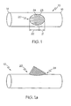
- FIG. 1 A first embodiment of the invention is depicted in FIG. 1 , wherein a stent, indicated generally at 10, is shown.
- the stent 10 can be self-expandable, balloon expandable or a hybrid and has a proximal end 14 and a distal end 16.
- a crown 20 Positioned between the distal and proximal ends of the stent 10 is a crown 20.
- the fingers 24 may vary in length and the majority of the fingers 24 extend longitudinally in either a distal or proximal direction from the crown with some fingers 24 extending at an angle that is not longitudinal. However, for purposes of this embodiment, those fingers 24 that extend with a longitudinal component will be considered to be on a distal portion 21 of the crown 20 if a component of its extension from the crown 20 is in a proximal direction and will be considered on a proximal portion 22 of the crown 20 if a component of its extension from the crown 20 is in a distal direction.
- the distally extending fingers 24 are generally longer than the proximally extending fingers 24.
- FIG. 1a illustrates an embodiment of the invention in which the fingers 24 positioned on crown 20 are in an expanded state.
- the combination of longer and shorter fingers 24 is designed to provide better carina coverage.
- a desirable embodiment would have fingers 24 that decrease in length from the proximal to the distal end of the crown 20, and for that matter, from the distal to the proximal end of the crown 20.
- a more desirable embodiment would have a decrease of similar increments in the length of the fingers 24.
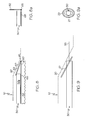
- FIG. 2 is a cross-sectional side view of an expanded stent 10 positioned at a bifurcation.
- the stent 10 includes crown 20 having longer fingers 24a and shorter fingers 24b which extend into the secondary lumen of the bifurcation. As illustrated in FIG. 2 , shorter fingers 24b are located at the carina 26 of the bifurcation.
- the longer fingers 24a and shorter fingers 24b are designed to extend in such a way that support is provided at the bifurcation, and as illustrated in FIG. 2a , when attachment to another stent 100 in the secondary lumen is desired, there is no gap in coverage.
- FIGS. 3 and 3a illustrate two cases with lesser coverages.
- FIG. 3 depicts a bifurcation in which the fingers 24 of the stent 10 are of a short equal length. The stent 100 in the secondary lumen can only engage the fingers 24 at one location. Thus a portion of the secondary lumen at the bifurcation remains uncovered.
- FIG. 3a depicts a bifurcation in which the fingers 24 of the stent 10 are long but of equal length. In this example, the fingers 24 extend into the secondary lumen at the bifurcation. However, coverage is again not full because to obtain full coverage, it is necessary to overlap one portion of the fingers 24 with the stent 100 in the secondary lumen.
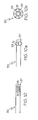
- FIG. 4a illustrates a stent 10 with a crown 20.
- the fingers 24 of the crown 20 overlap.
- the fingers 24 extending proximally overlap those extending distally.
- FIG. 4b illustrates a stent 10 with a crown 20.
- the fingers 24 of the crown 20 are interlaced.
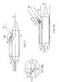
- FIG. 5a illustrates a stent 10, with a crown 20 that has longer fingers on the distal portion of the crown 20, inside a body lumen at the point of the bifurcation.
- the fingers 24 of the crown 20 begin to open before the main body of the stent 10 is fully deployed.
- treated bifurcations have a lumen opening 2.0 mm or greater. While the fingers can be of a length up to about 10.0 mm, for a finger 24 to flip into the bifurcated secondary lumen it is sometimes beneficial to limit the length of the finger 24 to about 1.5 mm to account for any misalignment in the placement of the stent 10.
- FIG. 5b depicts the stent of FIG. 5a after full deployment. As shown, the distal portion of the carina has very good coverage. Here a second stent 100 is present in the secondary lumen.
- FIG. 6 illustrates an apparatus 28 for deploying a stent 10 with a crown 20 at a bifurcation. Though this can be done in a self expanding stent, a balloon 40 is shown with the apparatus 28. The stent 10 is guided along guidewire 50. A pushing device 30, with a push plate tip 35, is located alongside the catheter and balloon 40 and extends under the stent 10 to the crown portion 20 of the stent 10. The pushing device 30 is guided by a guidewire 55.
- pushing device 30 includes a push plate 30a with a tip 35.
- the push plate 30 is guided along guidewire 55 and pushed forward through the crown 20.
- the push plate 30a forces the fingers outwardly and into the secondary lumen.
- FIG. 7a illustrates the view through the secondary lumen after the push plate 30a has been pushed through.
- FIG. 8 illustrates another example.
- the pushing device 30 includes an engaging mechanism 60 which is moveably disposed between the balloon 40 and push plate 30b.
- the mechanism 60 includes a longitudinal member 68 which extends along at least a portion of balloon 40 and includes a cantilever member 62.
- the push plate 30b engages and rotates the cantilever member 62 about a pivot position 65.
- the cantilever member 62 rotates, it engages the crown portion 20 of the stent 10 and opens the crown portion.
- FIG. 8a illustrates the end result of this movement.
- FIG. 9 illustrates another example in which a ring 27 is attached to the push device 30.
- the distal end of the ring 27 comes into contact with crown 20 and thereby rotates the proximal end of the ring so as to engage and force outward the fingers of the crown 20.
- FIG. 9a a view through the secondary lumen is shown.
- the ring 27 has fully engaged the fingers and extended them into the lumen 29.
- FIG. 10 Another example is illustrated in FIG. 10 .
- the pushing device 30 is a tube or rod in which the distal end is hollow and has spaced openings 31 around the distal end. Between each of these openings 31 a strip 33 of flexible material is extant.
- FIG. lova when distal movement is applied to the pushing device 30, the strips 33 bend outward under a compressive force created due to the end of the tube or rod having a fixed region of attachment 37 fixedly attached to the balloon or to an embodiment of the longitudinal member 68 of FIG. 8 .
- the fingers are contacted and forced outward into the secondary lumen 29.
- Fig. 10b illustrates the end result of this movement.
- FIGS. 11 and 11a another example is illustrated.
- a pushing device 30 includes web-like strands 43.
- the distal portion of device 30 will pass through the crown 40 and the strands 43 will engage the fingers 24 of the crown 40.
- a pulling motion is applied to the fingers 24 to deploy them.
- FIG. lib illustrates a device that pulls the fingers 24 to deploy them within a body lumen 70.
- the web-like strands 43 break free from the fingers 24 when a certain distance is traveled. This can be done using a number of materials.
- One example includes biophilial materials that break upon a designed-for tension.
- Another embodiment incorporates a material that acts in the manner of hook and loop material .
Landscapes
- Health & Medical Sciences (AREA)
- Engineering & Computer Science (AREA)
- Biomedical Technology (AREA)
- Cardiology (AREA)
- Oral & Maxillofacial Surgery (AREA)
- Transplantation (AREA)
- Heart & Thoracic Surgery (AREA)
- Vascular Medicine (AREA)
- Life Sciences & Earth Sciences (AREA)
- Animal Behavior & Ethology (AREA)
- General Health & Medical Sciences (AREA)
- Public Health (AREA)
- Veterinary Medicine (AREA)
- Media Introduction/Drainage Providing Device (AREA)
- Prostheses (AREA)
Claims (13)
- Stent (10), umfassend:eine röhrenförmige Struktur, die um eine erste Längsachse angeordnet ist;eine Mehrheit Finger (24), die sich, bei Expansion des Stents, von der röhrenförmigen Struktur um eine zweite Längsachse erstrecken, die abgewinkelt von der ersten Längsachse versetzt ist, wobei die Mehrheit Finger (24) um eine Öffnung (23) in dem Stent (10) angeordnet ist, wobei die Öffnung (23) und die Finger (24) eine Krone (20) bestimmen,dadurch gekennzeichnet, dass mindestens einer der Mehrheit Finger (24) eine Länge aufweist, die größer ist, als die der anderen Finger, wobei die Mehrheit Finger (24) eine erste Gruppe Finger (24) und eine zweite Gruppe Finger (24) umfasst, wobei die erste Gruppe Finger (24), die an einem proximalen Abschnitt (22) der Krone (20) positioniert ist, eine durchschnittliche Länge aufweist, und die zweite Gruppe Finger (24), die an einem distalen Abschnitt (21) der Krone (20) positioniert ist, eine durchschnittliche Länge aufweist, wobei die durchschnittliche Länge der ersten Gruppe Finger (24), die an dem proximalen Abschnitt (22) der Krone (20) positioniert ist, länger ist, als die durchschnittliche Länge der zweiten Gruppe Finger (24), die an dem distalen Abschnitt (21) der Krone positioniert ist.
- Stent (10) nach Anspruch 1, der eine Außenfläche aufweist, wobei, in einem nicht expandierten Zustand, die Finger (24) im Wesentlichen an der Außenfläche der röhrenförmigen Struktur liegen.
- Stent (10) nach Anspruch 1 oder 2, wobei mindestens einer der Finger (24), die an dem distalen Abschnitt (21) positioniert sind, kürzer ist, als einer der Finger an dem proximalen Abschnitt (22).
- Stent (10) nach einem der Ansprüche 1 bis 3, wobei, wenn sich die röhrenförmige Struktur in einem nicht expandierten Zustand befindet, mindestens einer der Finger (24), der an der Krone (20) positioniert ist, mit mindestens einem anderen Finger (24) an der Krone (20) überlappt.
- Stent (10) nach Anspruch 1, wobei, wenn sich die röhrenförmige Struktur in einem nicht expandierten Zustand befindet, die Finger (24) so miteinander verflochten sind, dass ein Abschnitt mindestens eines Fingers (24) mindestens teilweise zwischen zwei anderen Fingern (24) positioniert ist.
- Stent (10) nach Anspruch 1, wobei, wenn sich das röhrenförmige Element in einem nicht expandierten Zustand befindet, einige Finger (24) proximal zu anderen Fingern (24) sind und sich distal erstrecken, und einige Finger (24) distal zu anderen Fingern (24) sind und sich proximal erstrecken, und wobei sich die Finger (24), die proximal zu den anderen Fingern (24) sind, distal zu einem Längspunkt erstrecken, der proximal zu einem beliebigen Abschnitt der Finger (24) ist, die sich proximal erstrecken.
- Stent (10) nach Anspruch 1, wobei jeder der Finger (24) eine Länge von weniger als 10,0 mm aufweist.
- Stent (10) nach Anspruch 1, wobei jeder Finger (24) eine Länge aufweist, wobei einer der Finger (24) eine kürzere Länge aufweist, als die anderen Finger (24), wobei der Finger (24) mit der kürzeren Länge eine Länge von ungefähr 1,0 mm aufweist.
- Stent (10) nach Anspruch 1, wobei der Stent selbst-expandierbar ist.
- Stent (10) nach Anspruch 1, wobei der Stent (10) Ballon-expandierbar ist.
- Stent (10) nach Anspruch 1, wobei die Mehrheit Finger (24) in einem nicht expandierten Zustand so positioniert ist, dass sie sich inwärts zu einem Mittelbereich der Krone (20) erstreckt.
- Stent (10) nach Anspruch 1, wobei alle, außer mindestens einem der Mehrheit Finger (24), jeweils benachbart zu einem Finger (24) sind, der eine geringere Länge aufweist, und benachbart zu einem Finger (24), der eine längere Länge aufweist.
- Stent (10) nach Anspruch 1, wobei die Mehrheit Finger (24) an dem Stent zwei bis 25 Finger (24) umfasst.
Applications Claiming Priority (3)
| Application Number | Priority Date | Filing Date | Title |
|---|---|---|---|
| US288621 | 2002-11-05 | ||
| US10/288,621 US7326242B2 (en) | 2002-11-05 | 2002-11-05 | Asymmetric bifurcated crown |
| PCT/US2003/026382 WO2004043297A1 (en) | 2002-11-05 | 2003-08-22 | Assymmetric bifurcated crown |
Publications (2)
| Publication Number | Publication Date |
|---|---|
| EP1587448A1 EP1587448A1 (de) | 2005-10-26 |
| EP1587448B1 true EP1587448B1 (de) | 2012-02-29 |
Family
ID=32175929
Family Applications (1)
| Application Number | Title | Priority Date | Filing Date |
|---|---|---|---|
| EP03811208A Expired - Lifetime EP1587448B1 (de) | 2002-11-05 | 2003-08-22 | Asymmetrische gegabelte krone |
Country Status (6)
| Country | Link |
|---|---|
| US (3) | US7326242B2 (de) |
| EP (1) | EP1587448B1 (de) |
| JP (1) | JP4589119B2 (de) |
| AU (1) | AU2003262808A1 (de) |
| CA (1) | CA2494869A1 (de) |
| WO (1) | WO2004043297A1 (de) |
Families Citing this family (85)
| Publication number | Priority date | Publication date | Assignee | Title |
|---|---|---|---|---|
| US6835203B1 (en) | 1996-11-04 | 2004-12-28 | Advanced Stent Technologies, Inc. | Extendible stent apparatus |
| US6325826B1 (en) * | 1998-01-14 | 2001-12-04 | Advanced Stent Technologies, Inc. | Extendible stent apparatus |
| US6599316B2 (en) | 1996-11-04 | 2003-07-29 | Advanced Stent Technologies, Inc. | Extendible stent apparatus |
| EP1723931B1 (de) * | 1996-11-04 | 2012-01-04 | Advanced Stent Technologies, Inc. | Vorrichtung zum Ausdehnnen eines Stents und Verfahren zu seiner Entfaltung |
| US7341598B2 (en) | 1999-01-13 | 2008-03-11 | Boston Scientific Scimed, Inc. | Stent with protruding branch portion for bifurcated vessels |
| US7220275B2 (en) | 1996-11-04 | 2007-05-22 | Advanced Stent Technologies, Inc. | Stent with protruding branch portion for bifurcated vessels |
| US8257425B2 (en) * | 1999-01-13 | 2012-09-04 | Boston Scientific Scimed, Inc. | Stent with protruding branch portion for bifurcated vessels |
| JP2003525065A (ja) * | 1999-01-27 | 2003-08-26 | ボストン サイエンティフィック リミテッド | 分岐ステント送達システム |
| US20030097169A1 (en) | 2001-02-26 | 2003-05-22 | Brucker Gregory G. | Bifurcated stent and delivery system |
| US7147661B2 (en) | 2001-12-20 | 2006-12-12 | Boston Scientific Santa Rosa Corp. | Radially expandable stent |
| KR100893070B1 (ko) * | 2002-09-19 | 2009-04-17 | 엘지전자 주식회사 | 무선통신 시스템의 멀티캐스트 서비스 제공 및 수신 방법, 그리고 그 장치 |
| US8298280B2 (en) | 2003-08-21 | 2012-10-30 | Boston Scientific Scimed, Inc. | Stent with protruding branch portion for bifurcated vessels |
| US8007528B2 (en) * | 2004-03-17 | 2011-08-30 | Boston Scientific Scimed, Inc. | Bifurcated stent |
| EP1753369B1 (de) | 2004-06-08 | 2013-05-29 | Advanced Stent Technologies, Inc. | Stent mit herausragendem astteil für verzweigte gefässe |
| JP4928449B2 (ja) * | 2004-07-02 | 2012-05-09 | クック・インコーポレイテッド | 管腔内プロテーゼ |
| US20060030929A1 (en) * | 2004-08-09 | 2006-02-09 | Scimed Life Systems, Inc. | Flap-cover aneurysm stent |
| US9427340B2 (en) * | 2004-12-14 | 2016-08-30 | Boston Scientific Scimed, Inc. | Stent with protruding branch portion for bifurcated vessels |
| US9101500B2 (en) * | 2005-01-10 | 2015-08-11 | Trireme Medical, Inc. | Stent with self-deployable portion having wings of different lengths |
| CN101102728B (zh) * | 2005-01-10 | 2011-06-22 | 曲利姆医疗股份有限公司 | 具有可自展开部分的支架 |
| US8480728B2 (en) * | 2005-05-26 | 2013-07-09 | Boston Scientific Scimed, Inc. | Stent side branch deployment initiation geometry |
| US8317855B2 (en) * | 2005-05-26 | 2012-11-27 | Boston Scientific Scimed, Inc. | Crimpable and expandable side branch cell |
| US20060271161A1 (en) * | 2005-05-26 | 2006-11-30 | Boston Scientific Scimed, Inc. | Selective treatment of stent side branch petals |
| JP5037500B2 (ja) * | 2005-06-01 | 2012-09-26 | ウィリアム・エイ・クック・オーストラリア・プロプライエタリー・リミテッド | 側枝ステントグラフト |
| US20070050016A1 (en) * | 2005-08-29 | 2007-03-01 | Boston Scientific Scimed, Inc. | Stent with expanding side branch geometry |
| US8038706B2 (en) * | 2005-09-08 | 2011-10-18 | Boston Scientific Scimed, Inc. | Crown stent assembly |
| US7731741B2 (en) | 2005-09-08 | 2010-06-08 | Boston Scientific Scimed, Inc. | Inflatable bifurcation stent |
| US8043366B2 (en) | 2005-09-08 | 2011-10-25 | Boston Scientific Scimed, Inc. | Overlapping stent |
| US20070112418A1 (en) * | 2005-11-14 | 2007-05-17 | Boston Scientific Scimed, Inc. | Stent with spiral side-branch support designs |
| US20070118200A1 (en) * | 2005-11-18 | 2007-05-24 | Boston Scientific Scimed, Inc. | Bifurcation stent delivery system |
| US20070123970A1 (en) * | 2005-11-29 | 2007-05-31 | Boston Scientific Scimed, Inc. | Bifurcation stent with overlapping crimped struts |
| US7766893B2 (en) * | 2005-12-07 | 2010-08-03 | Boston Scientific Scimed, Inc. | Tapered multi-chamber balloon |
| US8435284B2 (en) | 2005-12-14 | 2013-05-07 | Boston Scientific Scimed, Inc. | Telescoping bifurcated stent |
| US8343211B2 (en) | 2005-12-14 | 2013-01-01 | Boston Scientific Scimed, Inc. | Connectors for bifurcated stent |
| US20070142904A1 (en) * | 2005-12-20 | 2007-06-21 | Boston Scientific Scimed, Inc. | Bifurcated stent with multiple locations for side branch access |
| US7540881B2 (en) | 2005-12-22 | 2009-06-02 | Boston Scientific Scimed, Inc. | Bifurcation stent pattern |
| FR2896983B1 (fr) * | 2006-02-09 | 2008-04-11 | Alain Dibie | Systeme de traitement de lesions sur une bifurcation de vaisseau sanguin |
| US20070208411A1 (en) * | 2006-03-06 | 2007-09-06 | Boston Scientific Scimed, Inc. | Bifurcated stent with surface area gradient |
| US7833264B2 (en) * | 2006-03-06 | 2010-11-16 | Boston Scientific Scimed, Inc. | Bifurcated stent |
| US20070208419A1 (en) * | 2006-03-06 | 2007-09-06 | Boston Scientific Scimed, Inc. | Bifurcation stent with uniform side branch projection |
| US8298278B2 (en) * | 2006-03-07 | 2012-10-30 | Boston Scientific Scimed, Inc. | Bifurcated stent with improvement securement |
| US20070260304A1 (en) * | 2006-05-02 | 2007-11-08 | Daniel Gregorich | Bifurcated stent with minimally circumferentially projected side branch |
| US20070288082A1 (en) * | 2006-06-07 | 2007-12-13 | Abbott Cardiovascular Systems Inc. | Stent and catheter assembly and method for treating bifurcations |
| US7922758B2 (en) | 2006-06-23 | 2011-04-12 | Boston Scientific Scimed, Inc. | Nesting twisting hinge points in a bifurcated petal geometry |
| US8216267B2 (en) | 2006-09-12 | 2012-07-10 | Boston Scientific Scimed, Inc. | Multilayer balloon for bifurcated stent delivery and methods of making and using the same |
| US7951191B2 (en) | 2006-10-10 | 2011-05-31 | Boston Scientific Scimed, Inc. | Bifurcated stent with entire circumferential petal |
| US8206429B2 (en) | 2006-11-02 | 2012-06-26 | Boston Scientific Scimed, Inc. | Adjustable bifurcation catheter incorporating electroactive polymer and methods of making and using the same |
| US8414611B2 (en) * | 2006-11-03 | 2013-04-09 | Boston Scientific Scimed, Inc. | Main vessel constraining side-branch access balloon |
| US8398695B2 (en) * | 2006-11-03 | 2013-03-19 | Boston Scientific Scimed, Inc. | Side branch stenting system using a main vessel constraining side branch access balloon and side branching stent |
| US20080177377A1 (en) * | 2006-11-16 | 2008-07-24 | Boston Scientific Scimed, Inc. | Bifurcation Stent Design with Over Expansion Capability |
| US7842082B2 (en) | 2006-11-16 | 2010-11-30 | Boston Scientific Scimed, Inc. | Bifurcated stent |
| US20080147174A1 (en) * | 2006-12-11 | 2008-06-19 | Trireme Medical, Inc. | Apparatus and method of using markers to position stents in bifurcations |
| US7959668B2 (en) | 2007-01-16 | 2011-06-14 | Boston Scientific Scimed, Inc. | Bifurcated stent |
| JP5662683B2 (ja) | 2007-02-09 | 2015-02-04 | タヘリ ラドュカ エルエルシー | 体内に植込型デバイスを展開する装置および方法 |
| US8118861B2 (en) * | 2007-03-28 | 2012-02-21 | Boston Scientific Scimed, Inc. | Bifurcation stent and balloon assemblies |
| US8647376B2 (en) | 2007-03-30 | 2014-02-11 | Boston Scientific Scimed, Inc. | Balloon fold design for deployment of bifurcated stent petal architecture |
| US20080300671A1 (en) * | 2007-06-04 | 2008-12-04 | Gil Vardi | Stent having high expansion ratio |
| US7959669B2 (en) | 2007-09-12 | 2011-06-14 | Boston Scientific Scimed, Inc. | Bifurcated stent with open ended side branch support |
| US7833266B2 (en) | 2007-11-28 | 2010-11-16 | Boston Scientific Scimed, Inc. | Bifurcated stent with drug wells for specific ostial, carina, and side branch treatment |
| US8277501B2 (en) | 2007-12-21 | 2012-10-02 | Boston Scientific Scimed, Inc. | Bi-stable bifurcated stent petal geometry |
| JP5504173B2 (ja) | 2007-12-31 | 2014-05-28 | ボストン サイエンティフィック サイムド,インコーポレイテッド | 血管分岐部の処置のためのカテーテルアセンブリ |
| US8932340B2 (en) | 2008-05-29 | 2015-01-13 | Boston Scientific Scimed, Inc. | Bifurcated stent and delivery system |
| US8133199B2 (en) | 2008-08-27 | 2012-03-13 | Boston Scientific Scimed, Inc. | Electroactive polymer activation system for a medical device |
| US12324756B2 (en) | 2008-09-25 | 2025-06-10 | Advanced Bifurcation Systems Inc. | System and methods for treating a bifurcation |
| US11298252B2 (en) | 2008-09-25 | 2022-04-12 | Advanced Bifurcation Systems Inc. | Stent alignment during treatment of a bifurcation |
| US12076258B2 (en) | 2008-09-25 | 2024-09-03 | Advanced Bifurcation Systems Inc. | Selective stent crimping |
| US8821562B2 (en) | 2008-09-25 | 2014-09-02 | Advanced Bifurcation Systems, Inc. | Partially crimped stent |
| US8828071B2 (en) | 2008-09-25 | 2014-09-09 | Advanced Bifurcation Systems, Inc. | Methods and systems for ostial stenting of a bifurcation |
| JP5635515B2 (ja) | 2008-09-25 | 2014-12-03 | アドバンスド バイファケーション システムズ, インコーポレイテッド | 部分的圧着ステント |
| US8052741B2 (en) * | 2009-03-23 | 2011-11-08 | Medtronic Vascular, Inc. | Branch vessel prosthesis with a roll-up sealing assembly |
| US9358099B2 (en) * | 2009-11-30 | 2016-06-07 | Biflow Medical Ltd. | Method of implanting a stent graft and creating a fenestration therein |
| EP2549952A4 (de) | 2010-03-24 | 2017-01-04 | Advanced Bifurcation Systems, Inc. | System und verfahren zur behandlung einer bifurkation |
| EP2549951B1 (de) | 2010-03-24 | 2017-05-10 | Advanced Bifurcation Systems, Inc. | Stentausrichtung während der behandlung einer bifurkation |
| CN103037815B (zh) | 2010-03-24 | 2015-05-13 | 高级分支系统股份有限公司 | 通过临时张开侧分支来处理分叉部的方法和系统 |
| WO2012109382A2 (en) | 2011-02-08 | 2012-08-16 | Advanced Bifurcation Systems, Inc. | Multi-stent and multi-balloon apparatus for treating bifurcations and methods of use |
| EP4424283A3 (de) | 2011-02-08 | 2024-12-25 | Advanced Bifurcation Systems Inc. | System und verfahren zur behandlung einer bifurkation mit einem vollständig gekräuselten stent |
| US20130073027A1 (en) * | 2011-09-16 | 2013-03-21 | Nikola Dobrilovic | Stent graft with flanged contralateral gate for endovascular aneurysm repair |
| CN104027187B (zh) | 2013-03-04 | 2016-05-25 | 微创心脉医疗科技(上海)有限公司 | 分支型覆膜支架、包括其的输送系统及其制造方法 |
| US10709587B2 (en) * | 2013-11-05 | 2020-07-14 | Hameem Unnabi Changezi | Bifurcated stent and delivery system |
| CN104116577B (zh) * | 2014-06-27 | 2017-07-14 | 先健科技(深圳)有限公司 | 分叉型覆膜支架 |
| WO2017218474A1 (en) * | 2016-06-13 | 2017-12-21 | Aortica Corporation | Systems, devices, and methods for marking and/or reinforcing fenestrations in prosthetic implants |
| WO2018156848A1 (en) * | 2017-02-24 | 2018-08-30 | Bolton Medical, Inc. | Vascular prosthesis with crimped adapter and methods of use |
| KR101937574B1 (ko) * | 2017-07-17 | 2019-01-11 | 울산대학교 산학협력단 | 복합 스텐트 및 그 제조방법 |
| EP3687445A2 (de) | 2017-09-25 | 2020-08-05 | Aortica Corporation | Systeme, vorrichtungen und verfahren zur kopplung eines prothetischen implantats an einem fenestrierten körper |
| US10792144B2 (en) | 2017-11-07 | 2020-10-06 | Nelson Rene Torales | Longitudinally and radially flexible anastomosis stent |
| CN110063824A (zh) * | 2019-06-10 | 2019-07-30 | 郑州美港高科生物科技有限公司 | 一种椎动脉支架 |
Family Cites Families (27)
| Publication number | Priority date | Publication date | Assignee | Title |
|---|---|---|---|---|
| US4994071A (en) | 1989-05-22 | 1991-02-19 | Cordis Corporation | Bifurcating stent apparatus and method |
| US5282860A (en) | 1991-10-16 | 1994-02-01 | Olympus Optical Co., Ltd. | Stent tube for medical use |
| US5540712A (en) * | 1992-05-01 | 1996-07-30 | Nitinol Medical Technologies, Inc. | Stent and method and apparatus for forming and delivering the same |
| US5609627A (en) | 1994-02-09 | 1997-03-11 | Boston Scientific Technology, Inc. | Method for delivering a bifurcated endoluminal prosthesis |
| CA2175720C (en) * | 1996-05-03 | 2011-11-29 | Ian M. Penn | Bifurcated stent and method for the manufacture and delivery of same |
| EP0813397A4 (de) | 1995-03-10 | 1999-10-06 | Cardiovascular Concepts Inc | Rohrförmige endoluminare prothese mit abgeschrägten enden |
| US6017363A (en) | 1997-09-22 | 2000-01-25 | Cordis Corporation | Bifurcated axially flexible stent |
| US6258116B1 (en) | 1996-01-26 | 2001-07-10 | Cordis Corporation | Bifurcated axially flexible stent |
| US6440165B1 (en) | 1996-05-03 | 2002-08-27 | Medinol, Ltd. | Bifurcated stent with improved side branch aperture and method of making same |
| DE69726829T2 (de) * | 1996-05-31 | 2004-10-07 | Ave Galway Ltd | Sich verzweigende endovaskuläre stents |
| EP1723931B1 (de) | 1996-11-04 | 2012-01-04 | Advanced Stent Technologies, Inc. | Vorrichtung zum Ausdehnnen eines Stents und Verfahren zu seiner Entfaltung |
| US6325826B1 (en) | 1998-01-14 | 2001-12-04 | Advanced Stent Technologies, Inc. | Extendible stent apparatus |
| US7220275B2 (en) * | 1996-11-04 | 2007-05-22 | Advanced Stent Technologies, Inc. | Stent with protruding branch portion for bifurcated vessels |
| WO1998020810A1 (en) * | 1996-11-12 | 1998-05-22 | Medtronic, Inc. | Flexible, radially expansible luminal prostheses |
| US6551350B1 (en) | 1996-12-23 | 2003-04-22 | Gore Enterprise Holdings, Inc. | Kink resistant bifurcated prosthesis |
| US6361544B1 (en) * | 1997-08-13 | 2002-03-26 | Advanced Cardiovascular Systems, Inc. | Stent and catheter assembly and method for treating bifurcations |
| US6520988B1 (en) | 1997-09-24 | 2003-02-18 | Medtronic Ave, Inc. | Endolumenal prosthesis and method of use in bifurcation regions of body lumens |
| US5893887A (en) | 1997-10-14 | 1999-04-13 | Iowa-India Investments Company Limited | Stent for positioning at junction of bifurcated blood vessel and method of making |
| US6033435A (en) | 1997-11-03 | 2000-03-07 | Divysio Solutions Ulc | Bifurcated stent and method for the manufacture and delivery of same |
| DE19938377A1 (de) * | 1999-08-06 | 2001-03-01 | Biotronik Mess & Therapieg | Stent für Gefässverzweigungen |
| US6387120B2 (en) | 1999-12-09 | 2002-05-14 | Advanced Cardiovascular Systems, Inc. | Stent and catheter assembly and method for treating bifurcations |
| NL1014559C2 (nl) | 2000-02-11 | 2001-08-14 | Surgical Innovations Vof | Umbrella-stent. |
| US7799064B2 (en) * | 2001-02-26 | 2010-09-21 | Boston Scientific Scimed, Inc. | Bifurcated stent and delivery system |
| US6749628B1 (en) | 2001-05-17 | 2004-06-15 | Advanced Cardiovascular Systems, Inc. | Stent and catheter assembly and method for treating bifurcations |
| US6878162B2 (en) * | 2002-08-30 | 2005-04-12 | Edwards Lifesciences Ag | Helical stent having improved flexibility and expandability |
| EP1753369B1 (de) * | 2004-06-08 | 2013-05-29 | Advanced Stent Technologies, Inc. | Stent mit herausragendem astteil für verzweigte gefässe |
| US20070208415A1 (en) * | 2006-03-06 | 2007-09-06 | Kevin Grotheim | Bifurcated stent with controlled drug delivery |
-
2002
- 2002-11-05 US US10/288,621 patent/US7326242B2/en not_active Expired - Lifetime
-
2003
- 2003-08-22 JP JP2004551439A patent/JP4589119B2/ja not_active Expired - Fee Related
- 2003-08-22 WO PCT/US2003/026382 patent/WO2004043297A1/en not_active Ceased
- 2003-08-22 EP EP03811208A patent/EP1587448B1/de not_active Expired - Lifetime
- 2003-08-22 AU AU2003262808A patent/AU2003262808A1/en not_active Abandoned
- 2003-08-22 CA CA002494869A patent/CA2494869A1/en not_active Abandoned
-
2008
- 2008-02-04 US US12/025,390 patent/US20080161905A1/en not_active Abandoned
-
2009
- 2009-09-15 US US12/559,910 patent/US20100004737A1/en not_active Abandoned
Also Published As
| Publication number | Publication date |
|---|---|
| US20080161905A1 (en) | 2008-07-03 |
| JP2006505343A (ja) | 2006-02-16 |
| WO2004043297A1 (en) | 2004-05-27 |
| US20040088007A1 (en) | 2004-05-06 |
| US20100004737A1 (en) | 2010-01-07 |
| CA2494869A1 (en) | 2004-05-27 |
| JP4589119B2 (ja) | 2010-12-01 |
| US7326242B2 (en) | 2008-02-05 |
| EP1587448A1 (de) | 2005-10-26 |
| AU2003262808A1 (en) | 2004-06-03 |
Similar Documents
| Publication | Publication Date | Title |
|---|---|---|
| EP1587448B1 (de) | Asymmetrische gegabelte krone | |
| CA2649381C (en) | Balloon expandable stent with a self-expanding portion | |
| US7799064B2 (en) | Bifurcated stent and delivery system | |
| EP0876805B1 (de) | Intravaskulärer Stent und System zum Einführen (Obstruktion des Ostiums eines Gefässes) | |
| US7758634B2 (en) | Bifurcated stent and delivery system | |
| US6099559A (en) | Endoluminal support assembly with capped ends | |
| US7473271B2 (en) | Stent delivery system with securement and deployment accuracy | |
| US7300456B2 (en) | Custom-length self-expanding stent delivery systems with stent bumpers | |
| US6740113B2 (en) | Balloon expandable stent with a self-expanding portion | |
| EP0969777B1 (de) | Aus einem bogen gewickelter schraubenfederförmiger stent mit spiralgliedern und sein gebrauchsverfahren | |
| EP1940315B1 (de) | Stent mit expandierender seitenast-geometrie | |
| US8652192B2 (en) | Stent and system and method for deploying a stent | |
| EP1527755A1 (de) | Abzweigender Stent mit flexiblem Seitenteil | |
| US7578840B2 (en) | Stent with reduced profile | |
| EP2552361B1 (de) | Systeme zur bereitstellung eines stents an einen körperlumen | |
| US20110054438A1 (en) | Stent delivery at a bifurcation, systems and methods |
Legal Events
| Date | Code | Title | Description |
|---|---|---|---|
| PUAI | Public reference made under article 153(3) epc to a published international application that has entered the european phase |
Free format text: ORIGINAL CODE: 0009012 |
|
| 17P | Request for examination filed |
Effective date: 20050507 |
|
| AK | Designated contracting states |
Kind code of ref document: A1 Designated state(s): AT BE BG CH CY CZ DE DK EE ES FI FR GB GR HU IE IT LI LU MC NL PT RO SE SI SK TR |
|
| AX | Request for extension of the european patent |
Extension state: AL LT LV MK |
|
| RAP1 | Party data changed (applicant data changed or rights of an application transferred) |
Owner name: BOSTON SCIENTIFIC SCIMED, INC. |
|
| DAX | Request for extension of the european patent (deleted) | ||
| RBV | Designated contracting states (corrected) |
Designated state(s): BE DE DK FR GB NL |
|
| 17Q | First examination report despatched |
Effective date: 20080811 |
|
| GRAP | Despatch of communication of intention to grant a patent |
Free format text: ORIGINAL CODE: EPIDOSNIGR1 |
|
| GRAS | Grant fee paid |
Free format text: ORIGINAL CODE: EPIDOSNIGR3 |
|
| GRAA | (expected) grant |
Free format text: ORIGINAL CODE: 0009210 |
|
| AK | Designated contracting states |
Kind code of ref document: B1 Designated state(s): BE DE DK FR GB NL |
|
| REG | Reference to a national code |
Ref country code: GB Ref legal event code: FG4D |
|
| REG | Reference to a national code |
Ref country code: DE Ref legal event code: R096 Ref document number: 60340170 Country of ref document: DE Effective date: 20120426 |
|
| REG | Reference to a national code |
Ref country code: NL Ref legal event code: T3 |
|
| PG25 | Lapsed in a contracting state [announced via postgrant information from national office to epo] |
Ref country code: BE Free format text: LAPSE BECAUSE OF FAILURE TO SUBMIT A TRANSLATION OF THE DESCRIPTION OR TO PAY THE FEE WITHIN THE PRESCRIBED TIME-LIMIT Effective date: 20120229 |
|
| PG25 | Lapsed in a contracting state [announced via postgrant information from national office to epo] |
Ref country code: DK Free format text: LAPSE BECAUSE OF FAILURE TO SUBMIT A TRANSLATION OF THE DESCRIPTION OR TO PAY THE FEE WITHIN THE PRESCRIBED TIME-LIMIT Effective date: 20120229 |
|
| PLBE | No opposition filed within time limit |
Free format text: ORIGINAL CODE: 0009261 |
|
| STAA | Information on the status of an ep patent application or granted ep patent |
Free format text: STATUS: NO OPPOSITION FILED WITHIN TIME LIMIT |
|
| 26N | No opposition filed |
Effective date: 20121130 |
|
| REG | Reference to a national code |
Ref country code: DE Ref legal event code: R097 Ref document number: 60340170 Country of ref document: DE Effective date: 20121130 |
|
| GBPC | Gb: european patent ceased through non-payment of renewal fee |
Effective date: 20120822 |
|
| PG25 | Lapsed in a contracting state [announced via postgrant information from national office to epo] |
Ref country code: GB Free format text: LAPSE BECAUSE OF NON-PAYMENT OF DUE FEES Effective date: 20120822 |
|
| PGFP | Annual fee paid to national office [announced via postgrant information from national office to epo] |
Ref country code: DE Payment date: 20130814 Year of fee payment: 11 Ref country code: NL Payment date: 20130810 Year of fee payment: 11 |
|
| PGFP | Annual fee paid to national office [announced via postgrant information from national office to epo] |
Ref country code: FR Payment date: 20130808 Year of fee payment: 11 |
|
| REG | Reference to a national code |
Ref country code: DE Ref legal event code: R082 Ref document number: 60340170 Country of ref document: DE Representative=s name: KANZLEI PFENNING, MEINIG & PARTNER GBR, DE |
|
| REG | Reference to a national code |
Ref country code: DE Ref legal event code: R119 Ref document number: 60340170 Country of ref document: DE |
|
| REG | Reference to a national code |
Ref country code: NL Ref legal event code: V1 Effective date: 20150301 |
|
| PG25 | Lapsed in a contracting state [announced via postgrant information from national office to epo] |
Ref country code: NL Free format text: LAPSE BECAUSE OF NON-PAYMENT OF DUE FEES Effective date: 20150301 |
|
| REG | Reference to a national code |
Ref country code: FR Ref legal event code: ST Effective date: 20150430 |
|
| REG | Reference to a national code |
Ref country code: DE Ref legal event code: R119 Ref document number: 60340170 Country of ref document: DE Effective date: 20150303 |
|
| PG25 | Lapsed in a contracting state [announced via postgrant information from national office to epo] |
Ref country code: DE Free format text: LAPSE BECAUSE OF NON-PAYMENT OF DUE FEES Effective date: 20150303 |
|
| PG25 | Lapsed in a contracting state [announced via postgrant information from national office to epo] |
Ref country code: FR Free format text: LAPSE BECAUSE OF NON-PAYMENT OF DUE FEES Effective date: 20140901 |