EP1587181A2 - Coaxial cable connector - Google Patents
Coaxial cable connector Download PDFInfo
- Publication number
- EP1587181A2 EP1587181A2 EP05252347A EP05252347A EP1587181A2 EP 1587181 A2 EP1587181 A2 EP 1587181A2 EP 05252347 A EP05252347 A EP 05252347A EP 05252347 A EP05252347 A EP 05252347A EP 1587181 A2 EP1587181 A2 EP 1587181A2
- Authority
- EP
- European Patent Office
- Prior art keywords
- collar
- post
- coaxial cable
- annular
- connector
- Prior art date
- Legal status (The legal status is an assumption and is not a legal conclusion. Google has not performed a legal analysis and makes no representation as to the accuracy of the status listed.)
- Withdrawn
Links
Images


Classifications
-
- H—ELECTRICITY
- H01—ELECTRIC ELEMENTS
- H01R—ELECTRICALLY-CONDUCTIVE CONNECTIONS; STRUCTURAL ASSOCIATIONS OF A PLURALITY OF MUTUALLY-INSULATED ELECTRICAL CONNECTING ELEMENTS; COUPLING DEVICES; CURRENT COLLECTORS
- H01R13/00—Details of coupling devices of the kinds covered by groups H01R12/70 or H01R24/00 - H01R33/00
- H01R13/62—Means for facilitating engagement or disengagement of coupling parts or for holding them in engagement
- H01R13/627—Snap or like fastening
- H01R13/6277—Snap or like fastening comprising annular latching means, e.g. ring snapping in an annular groove
-
- H—ELECTRICITY
- H01—ELECTRIC ELEMENTS
- H01R—ELECTRICALLY-CONDUCTIVE CONNECTIONS; STRUCTURAL ASSOCIATIONS OF A PLURALITY OF MUTUALLY-INSULATED ELECTRICAL CONNECTING ELEMENTS; COUPLING DEVICES; CURRENT COLLECTORS
- H01R24/00—Two-part coupling devices, or either of their cooperating parts, characterised by their overall structure
- H01R24/38—Two-part coupling devices, or either of their cooperating parts, characterised by their overall structure having concentrically or coaxially arranged contacts
- H01R24/40—Two-part coupling devices, or either of their cooperating parts, characterised by their overall structure having concentrically or coaxially arranged contacts specially adapted for high frequency
-
- H—ELECTRICITY
- H01—ELECTRIC ELEMENTS
- H01R—ELECTRICALLY-CONDUCTIVE CONNECTIONS; STRUCTURAL ASSOCIATIONS OF A PLURALITY OF MUTUALLY-INSULATED ELECTRICAL CONNECTING ELEMENTS; COUPLING DEVICES; CURRENT COLLECTORS
- H01R9/00—Structural associations of a plurality of mutually-insulated electrical connecting elements, e.g. terminal strips or terminal blocks; Terminals or binding posts mounted upon a base or in a case; Bases therefor
- H01R9/03—Connectors arranged to contact a plurality of the conductors of a multiconductor cable, e.g. tapping connections
- H01R9/05—Connectors arranged to contact a plurality of the conductors of a multiconductor cable, e.g. tapping connections for coaxial cables
- H01R9/0521—Connection to outer conductor by action of a nut
-
- H—ELECTRICITY
- H01—ELECTRIC ELEMENTS
- H01R—ELECTRICALLY-CONDUCTIVE CONNECTIONS; STRUCTURAL ASSOCIATIONS OF A PLURALITY OF MUTUALLY-INSULATED ELECTRICAL CONNECTING ELEMENTS; COUPLING DEVICES; CURRENT COLLECTORS
- H01R2103/00—Two poles
Definitions
- the present invention relates generally to connectors for terminating coaxial cable. More particularly, the present invention relates to a coaxial cable connector having fewer connector components and providing simpler installation.
- Conventional coaxial cables typically include a center conductor surrounded by an insulator.
- a conductive foil is disposed over the insulator and a braided conductive shield surrounds the foil covered insulator.
- An outer insulative jacket surrounds the shield.
- the outer jacket is stripped back exposing an extent of the braided conductive shield which is folded back over the jacket.
- a portion of the insulator covered by the conductive foil extends outwardly from the jacket and an extent of the center conductor extends outwardly from within the insulator.
- Such a prepared cable may be terminated in a conventional coaxial connector.
- Prior art coaxial connectors generally include a connector body having an annular collar for accommodating a coaxial cable, an annular nut rotatably coupled to the collar for providing mechanical attachment of the connector to an external device and an annular post interposed between the collar and the nut.
- the annular post Upon assembly to a coaxial cable, the annular post is inserted between the foil covered insulator and the conductive shield of the cable.
- a resilient sealing O-ring may also be positioned between the collar and the nut at the rotatable juncture thereof to provide a water resistant seal thereat.
- the collar includes a cable receiving end for insertably receiving an inserted coaxial cable and, at the opposite end of the connector body, the nut includes an internally threaded end extent permitting screw threaded attachment of the body to an external device.
- This type of coaxial connector further includes a locking sleeve to secure the cable within the body of the coaxial connector.
- the locking sleeve which is typically formed of a resilient plastic, is securable to the connector body to secure the coaxial connector thereto.
- the prior art coaxial cable connector included four distinct components: a rotatable nut; a connector body; an annular post; and a locking sleeve.
- a coaxial cable connector of this type is shown and described in commonly owned U.S. Patent No. 6,530,807.
- Such coaxial connectors are generally manufactured in large quantities at relatively low costs.
- One cost factor in manufacturing these connectors is the number of connector components that are required for assembly. Thus, eliminating just one component of the connector could significantly reduce the connector's manufacturing cost. Furthermore, fewer components could also simplify the cable installation process.
- the present invention provides a coaxial cable connector.
- the connector of the present invention generally includes an annular post defining an axial bore therein, a cylindrical collar movably coupled to the post and a nut rotatably coupled to the post.
- the post has a shoulder portion defined by an outer surface and a tubular extension extending axially rearwardly from the shoulder portion and the collar has a forward end movably coupled to the outer surface of the post shoulder portion.
- the collar and the post tubular extension define an annular chamber therebetween.
- the post may further include an annular sleeve portion extending rearwardly from the shoulder portion, which, together with the tubular extension, defines an annular pocket therebetween.
- the connector further preferably includes a sealing ring disposed between the post, the collar and the nut to provide a water resistant seal thereat.
- the post shoulder portion preferably includes a flanged base portion for securing the post in the nut.
- the outer surface of the post shoulder portion and the forward end of the collar preferably include cooperating detent structure for permitting axial movable connection of the collar and the post.
- This cooperating detent structure preferably includes an annular rib formed on one of the forward end of the collar and the outer surface of the post shoulder portion and two axially spaced annular grooves formed on the other of the forward end of the collar and the outer surface of the post shoulder portion.
- the annular rib may be provided on the collar and is preferably defined by a rearwardly facing perpendicular wall and a forwardly facing chamfered wall.
- the grooves are provided on the outer surface of the post shoulder portion and are defined by a forwardly facing perpendicular wall and a rearwardly facing chamfered wall to permit only forward movement of the collar on the post from a first position for loosely retaining a coaxial cable within the connector to a forward second position for securing the cable within the connector.
- the forward end of the collar may be press-fit on the outer surface of the post shoulder portion, or it may be threadably engaged with the outer surface of the post shoulder portion.
- the post shoulder portion preferably includes a rearwardly facing chamfered wall at a transition between the shoulder portion and the tubular extension to facilitate attachment of the collar to the post.
- the collar may be detachably coupled to the post.
- the collar may include a detachable arm extending outwardly therefrom for temporarily attaching the collar to the post in an initial configuration.
- the detachable arm may include a ring extension extending radially outwardly from the collar and a ring disposed at an end of the ring extension for attaching the collar to the post, wherein the ring is sized to be snugly fit on the outer surface of the post shoulder portion.
- the ring may include a slot breaking the continuity of the ring for facilitating perpendicular attachment of the ring to the post shoulder portion and the ring extension may include a frangible portion disposed where the extension meets the collar.
- the outer surface of the post shoulder portion and the ring may include cooperating detent structure for facilitating attachment of the ring to the post shoulder portion.
- the collar is movably coupled to a rearward interior surface of the rotatable nut in a first position and is movable forward to a second position, wherein the collar is coupled to the outer surface of the annular post.
- cooperating detent structure may be provided to facilitate forward movable connection of the collar and the post.
- the detent structure preferably includes an outwardly extending annular rib formed on an outer surface of the forward end of the collar, an inwardly extending annular rib formed on an inner surface of the forward end of the collar, a first annular groove formed on the inner surface of the nut and a second annular groove formed on the outer surface of the post shoulder portion.
- the present invention further involves a method for terminating a coaxial cable within a coaxial cable connector.
- the method generally includes the steps of inserting a prepared end of a coaxial cable into a rearward end of a cylindrical collar of the connector having a forward end movably coupled to an outer surface of an annular post of the connector and moving the collar forward on the outer surface of the annular post to a locked position wherein the cable is secured within the connector.
- the moving step preferably involves moving the collar from a first position wherein the cable is loosely retained within the connector to the locked position wherein the cable is secured within the connector.
- the moving step further preferably includes the step of disengaging a rib formed on one of the forward end of the collar and the outer surface of the annular post from a first groove formed on the other of the forward end of the collar and the outer surface of the annular post and engaging the rib in a second groove formed on the other of the forward end of the collar and the outer surface of the annular post.
- the method may further include the steps of detaching an arm of the collar from the outer surface of the annular post, detaching the arm from the collar and movably coupling the forward end of the collar to the outer surface of the annular post
- the inserting step may also include the step of inserting a shield portion of the prepared end of the coaxial cable into an annular pocket defined between an annular sleeve portion and a tubular extension of the annular post.
- the prepared end of a coaxial cable is inserted into a rearward end of a cylindrical collar of the connector that is initially apart from the annular post.
- the collar is then movably coupling to an outer surface of the annular post and moved forward on the outer surface of the annular post to a locked position wherein the cable is compressed between the inside of the collar and the outside of the post thereby locking the cable to the connector.
- the connector may be supplied in a configuration wherein the movable collar is initially temporarily attached to the post by a detachable arm.
- the user would first detach the collar from the post and then frangibly detach the arm from the collar.
- the collar would then be attachable to the post in its installation position for receiving a coaxial cable.
- the present invention is directed to connectors for terminating coaxial cable.
- Coaxial connectors of this type are shown and described in commonly owned U.S. Patent No. 6,530,807 issued August 28, 2003, the disclosure of which is incorporated herein by reference.
- connector 10 includes only three components: a movable collar 12; an annular post 14; and a rotatable nut 16.
- the collar 12 is an elongate generally cylindrical member, which may be formed of metal or plastic, having one end movably coupled to the post 14 and an opposite end for receiving a coaxial cable.
- the nut 16 may be in any form, such as a hex nut, knurled nut, wing nut, etc., and is rotatably coupled to the post 14 for providing mechanical attachment of the connector to an external device.
- a resilient sealing O-ring 18 may be positioned between the collar 12, the post 14 and the nut 16 at the rotatable juncture thereof to provide a water resistant seal thereat.
- the collar 12 includes a cable receiving end 20 for insertably receiving a prepared end of a coaxial cable.
- the nut 16 includes an internally threaded end extent 22 permitting screw threaded attachment of the connector body 10 to the external device.
- the cable receiving end 20 and the internally threaded end extension 22 define opposite ends of the connector 10.
- the annular post 14 includes a flanged base portion 24, which provides for press-fit securement of the post within a post receiving space in the nut 16.
- the annular post 14 further includes an elongated annular shoulder portion 26 having an outer surface which provides for movable attachment of the collar 12 to the post.
- the post 14 also includes an annular tubular extension 28 extending into the collar.
- the distal end of the tubular extension 28 includes a radially outwardly extending ramped flange portion 29 for compressing the outer jacket of the coaxial cable between the flange portion 29 and the internal diameter of the collar 12 to secure the cable within the connector.
- the extension 28 of the post 14 and the collar 12 define an annular chamber 30 for accommodating the jacket and shield of the inserted coaxial cable.
- the forward end 32 of the collar 12 and the shoulder portion 26 of the post 14 preferably include cooperative detent structure which allows for the movable connection of the collar 12 to the post 14 such that the collar is axially moveable along arrow A of Figures 2 and 3, towards nut 16 from a first position shown in Figure 2, which loosely retains the cable within the connector body 10, to a more forward second position shown in Figure 3, which secures the cable within the connector.
- the collar 12 may be press-fit onto the shoulder portion 26 of the collar 12 whereby the cable is locked in position by the friction fit between the post 14 and the collar 12 and between the post ramped flange 29 and the collar.
- the post shoulder portion 26 and the internal diameter of the collar 12 may be provided with mating cooperating threads for movably securing the collar to the post 14 between its first and second position.
- the connector 10 of the present invention is constructed so as to be supplied in the assembled condition shown in Figure 2, wherein the collar 12 is attached to the post 14 in its first position.
- a coaxial cable may be inserted through the rearward end 20 of the collar 12.
- the collar 12 may then be moved from the first position loosely retaining the cable to the second position which is axially forward thereby locking the cable within the connector.
- the connector 10 may be provided with securing means such that the collar 12 may be detachably coupled to the post 14 and, in a manner which will be described in further detail hereinbelow, will allow the coaxial cable to be first inserted directly into the post 14 unobstructed by the collar. Thereafter, the collar 12, which has been earlier placed around the cable, may be reattached to the post 14 where it can be moved from the first position to the second position locking the cable within the connector.
- the cooperating detent structure mentioned above is but one exemplary structure employed to provide such attachment and movement of the collar 12 to the post 14.
- Forward end 32 of the collar 12 includes a radially inwardly directed annular rib 34 extending adjacent the distal end thereof. Rib 34 is defined by a rearwardly facing perpendicular wall 36 and a forwardly facing chamfered wall 38.
- the cooperating detent structure of the present invention further includes the shoulder portion 26 of the post 14 formed to have two radially outwardly opening annular grooves 40 and 41 constructed so as to receive the rib 34 of the collar 12. The grooves 40 and 41 are axially spaced on the shoulder portion 26 of the post to define a rearward groove 40 and a forward groove 41.
- Both grooves 40 and 41 may include a forwardly facing perpendicular wall 42 and a rearwardly facing chamfered wall 44, which respectively engage the perpendicular wall 36 and the chamfered wall 38 of the collar rib 34.
- a forwardly facing perpendicular wall 42 and a rearwardly facing chamfered wall 44 which respectively engage the perpendicular wall 36 and the chamfered wall 38 of the collar rib 34.
- the post 14 may be inserted into the forward end 32 of the collar 12 until the rib 34 of the collar comes to rest within the rearward groove 40 of the post shoulder portion 26.
- the transition of the post between the shoulder portion 26 and the annular tubular extension 28 may also be provided with a rearwardly facing chamfered wall 46.
- the forward chamfered wall 38 of the collar rib 34 bears against the rearward chamfered wall 46 of the post shoulder portion transition.
- the collar 12 By its tubular shape, the collar 12 will have some resiliency at its forward end 32 which will allow the rib 34 to ride over the rearward chamfered wall 46 of the post shoulder portion 26 until the rib becomes lockingly resident within the rearward groove 40 of the post shoulder portion. This defines the first position of the collar 12.
- the cooperative detent structure of the present invention further includes a radially outwardly extending forward groove 41 formed on the shoulder portion 26 of the post 14 adjacent the rearward groove 40.
- the rib 34 of the collar Upon continued coaxial movement of the collar 12 along arrow A, the rib 34 of the collar disengages the rearward groove 40 and becomes resident within the forward groove 41 to define the second position of the collar which locks the collar in this position, thereby locking the cable within the connector.
- Coaxial cable 50 includes an inner conductor 52 formed of copper or similar conductive material. Extending around the inner conductor 52 is an insulator 54 formed of a suitably insulative plastic. A metallic foil 53 is disposed over the insulator 54 and a metallic shield 56 is positioned in surrounding relationship around the foil covered insulator. Covering the metallic shield 56 is an outer insulative jacket 58.
- Cable 50 is prepared in conventional fashion for termination by stripping back jacket 58 exposing an extent of shield 56.
- a portion of the foil covered insulator 54 extends therefrom with an extent of conductor 52 extending from insulator 54.
- the preparation process includes folding back an end extent of shield 56 about jacket 58.
- cable 50 may be inserted into the connector 10 with the collar 12 coupled to the post 14 as shown in Figure 2.
- the prepared cable 50 is inserted through the rearward end 20 of the collar 12.
- the extension 28 of the post 14 is inserted between the foil covered insulator 54 and the metallic shield 56 such that the shield and the jacket 58 reside within the annular region 30 defined between the post 14 and the collar 12.
- the collar 12 may be moved axially forward from the first position shown in Figures 2 and 5, to the second position shown in Figure 3.
- the rib 34 formed in the forward end 32 of the collar 12 disengages the rearward groove 40 formed in the shoulder portion 26 of the post 14.
- the collar 12 is moved axially forward until the collar rib 34 engages the forward groove 41 formed in the shoulder portion 26 of the post 14.
- the jacket 58 and shield 56 of the cable 50 begins to become compressively clamped within the annular region 30 between the post 14 and the collar 12.
- the perpendicular walls 36 and 42 of the rib 34 and the forward groove 41 help to maintain the collar 12 in the second position with respect to the post 14.
- a suitable tool may be used to effect movement of the collar 12 from its first position to its second position securing cable 50 to the connector 10.
- the installer may not have clear and convenient access when terminating the cable 50.
- insertion may be rendered difficult by poor cable preparation, which may result in a frayed end. Therefore, it may be difficult for the installer to blindly insert the cable 50 through the collar 12 and into the connector body 10.
- the present invention contemplates the ability to detachably remove the collar 12 from the post 14 so that the cable may be directly connected to the extension 28 of the post 14.
- the collar 12 is detachably removed from the post 14 in a manner facilitated as above described.
- the collar 12 is then slipped over the cable 50 and moved to a convenient position along the cable length.
- the end of the foil covered insulator 54 may then be inserted directly into the post extension 28 so that the extension is interposed between the foil covered insulator 54 and the shield 56.
- the collar 12 may be brought up along the cable 50 and the forward end 32 of the collar may be slipped over the shoulder portion 26 of the post 14.
- the respective chamfered walls 38 and 46 of the collar rib 34 and the shoulder portion transition facilitates insertion of the post 14 into the collar 12 so that the collar rib becomes resident within the rearward groove 40 as shown in Figures 2 and 5 defining the first position.
- the collar 12 may be moved from the first position shown in Figures 2 and 5 to a second position shown in Figure 3 where the rib 34 becomes resident within the forward groove 41 of the post 14 thereby locking the cable 50 in the connector 10.
- the collar 12 may simply be removably press-fit over the post shoulder portion 26 without the use of any detent structure. In this case, the same installation method would apply to secure the coaxial cable within the connector.
- FIGS 6-12 an alternative embodiment 110 of the coaxial cable connector formed in accordance with the present invention is shown.
- Figures 6, 7 and 7a show the coaxial cable connector 110 of the alternative embodiment in its initial configuration as supplied to an installer.
- Connector 110 includes three major components: a movable collar 112; an annular post 114; and a rotatable nut 116.
- the collar 112 is an elongate generally cylindrical member, which may be formed of metal or plastic, and having one end movably coupled to the post 114 and an opposite end for receiving a coaxial cable.
- the nut 116 may be in any form, such as a hex nut, knurled nut, wing nut, etc., and is rotatably coupled to the post 114 for providing mechanical attachment of the connector to an external device.
- a resilient sealing O-ring 118 may be positioned between the collar 112, the post 114 and the nut 116 at the rotatable juncture thereof to provide a water resistant seal thereat.
- the collar 112 is initially temporarily attached to the post 114 by a detachable arm 113 including a ring 115 and a ring extension 117.
- the ring 115 is sized to receive and be snugly fitted over a shoulder portion 126 of the post 114.
- the ring 115 may take the form of a split-ring wherein a slot 119 breaks the continuity of the ring to facilitate easy attachment and detachment of the collar 112 to the post 114.
- the collar 112 may be attached and detached from the post 114 in a direction perpendicular to the post axis, as opposed to being longitudinally slipped over the post shoulder section.
- the ring 115 further preferably includes a radially inwardly directed annular rib 119 defined by a rearwardly facing perpendicular wall 121 and a forwardly facing chamfered wall 123.
- the rib 119 of the ring 115 engages a radially outwardly opening annular forward groove 141 formed in the shoulder portion 126 of the post 114 to secure the ring to the post.
- the forward groove 141 preferably includes a forwardly facing perpendicular wall 142 and a rearwardly facing chamfered wall 144, which respectively engages the perpendicular wall 121 and the chamfered wall 123 of the ring rib 119.
- the ring 115 may be longitudinally slipped over the post 114 or, where the ring is a split-ring, it may be laterally snapped in place whereby the rib 119 of the ring comes to rest within the forward groove 141 of the post shoulder portion 126.
- the ring rib 119 is provided with the forward chamfered wall 123 which, when seated, bears against the rearward chamfered wall 144 of the forward groove 141.
- the rearward facing perpendicular wall 121 of the ring rib 119 bearing against the forward facing perpendicular wall 142 of the forward groove 141 prevents inadvertent rearward axial movement of the ring 115.
- the ring 115 is connected to the collar 112 by a radially outwardly extending ring extension 117.
- the ring extension 117 preferably includes a frangible portion 125 disposed where the extension meets the collar 112.
- the frangible portion 125 may include a perforation, slit, groove or other structure for permitting the ring extension 117 to be easily and cleanly detached from the collar 112.
- the detachable arm 113 including the ring 115 and the ring extension 117, has no further use and may be discarded.
- the collar 112 is now preferably slipped over the end of a prepared coaxial cable or, alternatively, the collar may be attached first to the post 114.
- the collar 112 includes a cable receiving end 120 for insertably receiving a prepared end of a coaxial cable.
- the nut 116 includes an internally threaded end extent 122 permitting screw threaded attachment of the connector body 110 to the external device.
- the cable receiving end 120 and the internally threaded end extension 122 define opposite ends of the connector 110.
- the annular post 114 includes a flanged base portion 124 which provides for press-fit securement of the post within a post receiving space in the nut 116.
- the annular post 114 further includes an elongated annular shoulder portion 126 having an outer surface, which provides for movable attachment of the collar 112 to the post.
- the post 114 also includes an annular sleeve portion 127 extending rearwardly from the shoulder portion and an annular tubular extension 128 extending from within the sleeve portion into the collar.
- the sleeve portion 127 and the tubular extension 128 of the post 114 define an annular pocket 129 therebetween and the post extension 128 and the collar 112 define an annular chamber 130.
- the distal end of the tubular extension 128 includes a radially outwardly extending ramped flange portion 131 for compressing the outer jacket of the coaxial cable in the annular chamber 130 between the flange portion and the internal diameter of the collar 112 to secure the cable within the connector.
- both the pocket 129 and the chamber 130 are designed for accommodating the jacket and shield of the inserted coaxial cable.
- the forward end 132 of the collar 112 and the shoulder portion 126 of the post 114 preferably include cooperative detent structure which allows for the movable connection of the collar 112 to the post 114 such that the collar is axially moveable along arrow A of Figures 8-12, towards nut 116 from a first position shown in Figure 8, which loosely retains the cable within the connector body 110, to a more forward second position shown in Figure 9, which secures the cable within the connector.
- the collar may first be slipped onto the cable before insertion of the cable into the post, only the second, locked position may be provided with cooperating structure to lock the collar in the closed position.
- the connector 110 of the present invention is constructed so as to be supplied in the pre-assembled condition shown in Figures 6 and 7, wherein the collar 112 is temporarily attached to the post 114 by the detachable arm 113.
- the collar 112 which is still attached to the post 114 in its pre-assembled condition, is slipped onto an end of a prepared cable 150. Once positioned on the cable 150, the collar 112 is detached from the post 114 via the frangible arm 113. In this manner, there is less chance that the installer will drop or lose either of the two components of the connector assembly.
- a coaxial cable may be inserted through the rearward end 120 of the collar 112 and connected directly to the post 114. Thereafter, the collar 112 may be attached to the post 114 where it can be moved from the first position to the second position locking the cable within the connector.
- Forward end 132 of the collar 112 includes a radially inwardly directed annular rib 134 extending adjacent the distal end thereof. Rib 134 is defined by a rearwardly facing perpendicular wall 136 and a forwardly facing chamfered wall 138.
- the cooperating detent structure of the present invention further includes the shoulder portion 126 of the post 114 formed to have two radially outwardly opening annular grooves 140 and 141 constructed so as to receive the rib 134 of the collar 112.
- the grooves 140 and 141 are axially spaced on the shoulder portion 126 of the post to define a rearward groove 140 and a forward groove 141.
- Both grooves 140 and 141 may include a forwardly facing perpendicular wall 142 and a rearwardly facing chamfered wall 144, which respectively engage the perpendicular wall 136 and the chamfered wall 138 of the collar rib 134. Where it is desired to have the collar 112 detachable from the post 114 after the collar has been placed in its first position, it is preferable to eliminate the perpendicular wall 142 from the rearward groove 140 and substitute a forwardly facing chamfered wall in its place.
- the forward end 132 of the collar 112 may be fitted over the sleeve portion 127 of the post 114 and slid forward until the rib 134 of the collar comes to rest within the rearward groove 140 of the post shoulder portion 126.
- the rib 134 is provided with a forward facing chamfered wall 138, as described above.
- the collar 112 will have some resiliency at its forward end 132 which will allow the rib 134 to ride over the sleeve portion 127 of the post 114 until the rib becomes lockingly resident within the rearward groove 140 of the post shoulder portion 126. This defines the first position of the collar 112.
- the cooperative detent structure of the present invention further includes a radially outwardly extending forward groove 141 formed on the shoulder portion 126 of the post 114 adjacent the rearward groove 140.
- the rib 134 of the collar Upon continued coaxial movement of the collar 112 along arrow A, the rib 134 of the collar disengages the rearward groove 140 and becomes resident within the forward groove 141 to define the second position of the collar which locks the collar in this position, thereby locking the cable within the connector.
- coaxial cable 150 is prepared in conventional fashion for termination by stripping back jacket 158 exposing an extent of shield 156.
- a portion of the foil covered insulator 154 extends therefrom with an extent of conductor 152 extending from insulator 154.
- the preparation process includes folding back an end extent of shield 156 about jacket 158.
- the collar 112 of the connector assembly 110 is preferably slipped over the end of a coaxial cable 150 and moved to a convenient position along the cable length prior to connecting the cable to the post 114.
- the post 114 may then be detached from the arm ring 115 and the frangible arm extension 117 may be detached from the collar 112. If desired, the installer may detach the collar prior to slipping the collar on the cable depending upon the installation.
- the collar 112 is oriented on the cable 150 so that the forward end 132 of the collar faces the end of the cable which will be prepared and inserted into the post 114.
- the end of the foil covered insulator 154 may then be inserted directly into the post extension 128 so that the extension is interposed between the foil covered insulator 154 and the shield 156.
- the cable 150 is then further pushed forward whereby the folded-over portion of the shield 156 is inserted into the post pocket 129 defined between the post sleeve portion and the post tubular extension 128, as shown in Figure 12.
- the folded-over portion of the shield 156 that becomes resident within the post pocket 129 is now protected from damage which may occur upon further assembly of the connector.
- the post pocket 129 protects the exposed portion of the shield 156 from damage that may be caused by the collar 112 as it is moved forward on the post 114 to lock the cable 150 within the connector 110 as described further below.
- the collar 112 may be brought up along the cable 150 and the forward end 132 of the collar may be slipped forward over the sleeve portion 127 and the shoulder portion 126 of the post 114 until the collar rib 134 becomes resident within the rearward groove 140 as shown in Figures 8 and 9 defining the first position.
- the collar 112 may be brought up along the cable 150 and the forward end 132 of the collar may be slipped forward over the sleeve portion 127 and the shoulder portion 126 of the post 114 until the collar rib 134 becomes resident within the rearward groove 140 as shown in Figures 8 and 9 defining the first position.
- the collar 112 is then further moved axially forward from the first position shown in Figures 8 and 10, to the second position shown in Figure 9.
- the collar 112 is moved axially forward, the rib 134 formed in the forward end 132 of the collar 112 disengages the rearward groove 140 formed in the shoulder portion 126 of the post 114.
- Such movement is facilitated by the forward facing chamfered wall 138 of the collar rib 134 and the cooperating rearward facing chamfered wall 144 of the rearward groove 140.
- the collar 112 is moved axially forward until the collar rib 134 engages the forward groove 141 formed in the shoulder portion 126 of the post 114.
- a suitable tool may be used to effect movement of the collar 112 from its first position to its second position securing the cable 150 to the connector 110.
- the jacket 158 of the cable 150 becomes compressively clamped within the annular chamber 130 between the extension 128 of the post 114 and the collar 112.
- the perpendicular walls 136 and 142 of the rib 134 and the forward groove 141 help to maintain the collar 112 in the second position with respect to the post 114 thereby locking the cable 150 within the connector 110.
- the collar 112 may first be assembled to the post 114 in its first position as shown in Figures 8 and 10 and the cable 150 may be subsequently inserted into the collar.
- the prepared cable 150 is inserted through the rearward end 120 of the collar 112 while the collar is connected to the post 114 in its first position.
- the extension 128 of the post 114 is inserted between the insulator 154 and the metallic shield 156 such that the folded-over portion of the shield resides within the post pocket 129 defined between the post sleeve portion 127 and the tube extension 128 and the uncovered jacket 158 resides within the annular region 130 defined between the post 114 and the collar 112.
- the collar 112 may be moved from the first position shown in Figures 8 and 10 to a second position shown in Figure 9 where the rib 134 becomes resident within the forward groove 141 of the post 114 thereby locking the cable 150 within the connector 110.
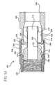
- the connector 200 includes the same three major components: a movable collar 202; an annular post 204; and a rotatable nut 206.
- the movable collar 202 is coupled to the nut 206 in a first position and is movable to a second position, wherein the collar is coupled to the post 204.
- the nut 206 in this embodiment extends further rearwardly and includes a rearward interior surface 208 having structure to engage the collar 202 in a first position.
- the post 204 again includes an axial bore 210 therein, a shoulder portion 212 defined by an outer surface 214 and a tubular extension 216 extending axially rearwardly from the shoulder portion.
- the outer surface 214 of the post shoulder portion 212 includes structure for coupling the collar 202 only in its second position.
- the forward end 218 of the collar includes structure on both its outer surface 220 and its inner surface 222 to respectively engage the inner surface 208 of the nut 206 and the outer surface 214 of the post shoulder portion 212.
- the securing means for coupling the collar 202 to the other connector components preferably takes the form of cooperating detent structure, wherein the outer surface 220 of the collar 202 includes an outwardly extending annular rib 224 formed thereon and the inner surface 222 of the collar includes an inwardly extending annular rib 226 formed thereon.
- the inner surface 208 of the nut 206 includes a first annular groove 228 formed thereon and the outer surface 214 of the post shoulder portion 212 includes a second annular groove 230 formed thereon.
- annular ribs 224 and 226 and grooves 228 and 230 may be reversed, wherein the grooves are provided on the collar and the ribs are provided on the nut and the post.
- the annular ribs 224 are preferably defined by a rearwardly facing perpendicular wall 232 and a forwardly facing chamfered wall 234 and the annular grooves 228 and 230 are preferably defined by a forwardly facing perpendicular wall 236 and a rearwardly facing chamfered wall 238 to permit only forward movement of the collar.
- the post shoulder portion 212 of this embodiment may also include a rearwardly facing chamfered wall 240 at a transition between the shoulder portion and the tubular extension 216 to facilitate attachment of the collar 202 to the post.
- the post may further include an annular sleeve portion (not shown in Figures 13 and 14) extending rearwardly from the shoulder portion 212, which defines an annular pocket between the sleeve portion and the tubular extension, as shown in Figures 6-12.
- a coaxial cable may be inserted through the rearward end 242 of the collar 202 and the collar may then be moved from its first position, as shown in Figure 13, thereby loosely retaining the cable, to an axially forward second position, as shown in Figure 14, thereby locking the cable within the connector.
Landscapes
- Coupling Device And Connection With Printed Circuit (AREA)
- Details Of Connecting Devices For Male And Female Coupling (AREA)
Abstract
Description
- This application claims the benefit of U.S. Provisional Application No. 60/562,953, filed on April 16, 2004, and U.S. Provisional Application No. 60/562,952, filed on April 16, 2004.
- The present invention relates generally to connectors for terminating coaxial cable. More particularly, the present invention relates to a coaxial cable connector having fewer connector components and providing simpler installation.
- It has long been known to use connectors to terminate coaxial cable so as to connect a cable to various electronic devices such as televisions, radios and the like.
- Conventional coaxial cables typically include a center conductor surrounded by an insulator. A conductive foil is disposed over the insulator and a braided conductive shield surrounds the foil covered insulator. An outer insulative jacket surrounds the shield. In order to prepare the coaxial cable for termination, the outer jacket is stripped back exposing an extent of the braided conductive shield which is folded back over the jacket. A portion of the insulator covered by the conductive foil extends outwardly from the jacket and an extent of the center conductor extends outwardly from within the insulator. Such a prepared cable may be terminated in a conventional coaxial connector.
- Prior art coaxial connectors generally include a connector body having an annular collar for accommodating a coaxial cable, an annular nut rotatably coupled to the collar for providing mechanical attachment of the connector to an external device and an annular post interposed between the collar and the nut. Upon assembly to a coaxial cable, the annular post is inserted between the foil covered insulator and the conductive shield of the cable. A resilient sealing O-ring may also be positioned between the collar and the nut at the rotatable juncture thereof to provide a water resistant seal thereat. The collar includes a cable receiving end for insertably receiving an inserted coaxial cable and, at the opposite end of the connector body, the nut includes an internally threaded end extent permitting screw threaded attachment of the body to an external device.
- This type of coaxial connector further includes a locking sleeve to secure the cable within the body of the coaxial connector. The locking sleeve, which is typically formed of a resilient plastic, is securable to the connector body to secure the coaxial connector thereto. Thus, the prior art coaxial cable connector included four distinct components: a rotatable nut; a connector body; an annular post; and a locking sleeve. A coaxial cable connector of this type is shown and described in commonly owned U.S. Patent No. 6,530,807.
- Such coaxial connectors are generally manufactured in large quantities at relatively low costs. One cost factor in manufacturing these connectors is the number of connector components that are required for assembly. Thus, eliminating just one component of the connector could significantly reduce the connector's manufacturing cost. Furthermore, fewer components could also simplify the cable installation process.
- It is, therefore, desirable to provide a coaxial connector having fewer components. In particular, it would be desirable to provide a coaxial connector that eliminates the need for a locking sleeve altogether. As a result, the number of components of the connector would be reduced, along with the connector's associated manufacturing costs, and the cable installation process would be simplified.
- It is an object of the present invention to provide a coaxial cable connector for terminating a coaxial cable.
- It is a further object of the present invention to provide a coaxial cable connector having fewer components and, therefore, a lower manufacturing cost.
- It is a further object of the present invention to simplify the cable installation process.
- It is another object of the present invention to provide a method of terminating a coaxial cable.
- In the efficient attainment of these and other objects, the present invention provides a coaxial cable connector. The connector of the present invention generally includes an annular post defining an axial bore therein, a cylindrical collar movably coupled to the post and a nut rotatably coupled to the post. The post has a shoulder portion defined by an outer surface and a tubular extension extending axially rearwardly from the shoulder portion and the collar has a forward end movably coupled to the outer surface of the post shoulder portion.
- In a preferred embodiment, the collar and the post tubular extension define an annular chamber therebetween. The post may further include an annular sleeve portion extending rearwardly from the shoulder portion, which, together with the tubular extension, defines an annular pocket therebetween. The connector further preferably includes a sealing ring disposed between the post, the collar and the nut to provide a water resistant seal thereat. Also, the post shoulder portion preferably includes a flanged base portion for securing the post in the nut.
- For coupling the collar to the post, the outer surface of the post shoulder portion and the forward end of the collar preferably include cooperating detent structure for permitting axial movable connection of the collar and the post. This cooperating detent structure preferably includes an annular rib formed on one of the forward end of the collar and the outer surface of the post shoulder portion and two axially spaced annular grooves formed on the other of the forward end of the collar and the outer surface of the post shoulder portion. The annular rib may be provided on the collar and is preferably defined by a rearwardly facing perpendicular wall and a forwardly facing chamfered wall. In this case, the grooves are provided on the outer surface of the post shoulder portion and are defined by a forwardly facing perpendicular wall and a rearwardly facing chamfered wall to permit only forward movement of the collar on the post from a first position for loosely retaining a coaxial cable within the connector to a forward second position for securing the cable within the connector.
- In alternative embodiments, the forward end of the collar may be press-fit on the outer surface of the post shoulder portion, or it may be threadably engaged with the outer surface of the post shoulder portion. In any event, the post shoulder portion preferably includes a rearwardly facing chamfered wall at a transition between the shoulder portion and the tubular extension to facilitate attachment of the collar to the post.
- In other alternative embodiments, the collar may be detachably coupled to the post. Additionally, the collar may include a detachable arm extending outwardly therefrom for temporarily attaching the collar to the post in an initial configuration. The detachable arm may include a ring extension extending radially outwardly from the collar and a ring disposed at an end of the ring extension for attaching the collar to the post, wherein the ring is sized to be snugly fit on the outer surface of the post shoulder portion. The ring may include a slot breaking the continuity of the ring for facilitating perpendicular attachment of the ring to the post shoulder portion and the ring extension may include a frangible portion disposed where the extension meets the collar. Moreover, the outer surface of the post shoulder portion and the ring may include cooperating detent structure for facilitating attachment of the ring to the post shoulder portion.
- In still another alternative embodiment, the collar is movably coupled to a rearward interior surface of the rotatable nut in a first position and is movable forward to a second position, wherein the collar is coupled to the outer surface of the annular post. Here too, cooperating detent structure may be provided to facilitate forward movable connection of the collar and the post. Specifically, the detent structure preferably includes an outwardly extending annular rib formed on an outer surface of the forward end of the collar, an inwardly extending annular rib formed on an inner surface of the forward end of the collar, a first annular groove formed on the inner surface of the nut and a second annular groove formed on the outer surface of the post shoulder portion.
- The present invention further involves a method for terminating a coaxial cable within a coaxial cable connector. The method generally includes the steps of inserting a prepared end of a coaxial cable into a rearward end of a cylindrical collar of the connector having a forward end movably coupled to an outer surface of an annular post of the connector and moving the collar forward on the outer surface of the annular post to a locked position wherein the cable is secured within the connector.
- In a preferred embodiment of the method, during the moving step, the cable end is compressed within an annular chamber formed between the collar and a tubular extension of the post extending axially rearward from the shoulder portion. Also, the moving step preferably involves moving the collar from a first position wherein the cable is loosely retained within the connector to the locked position wherein the cable is secured within the connector. The moving step further preferably includes the step of disengaging a rib formed on one of the forward end of the collar and the outer surface of the annular post from a first groove formed on the other of the forward end of the collar and the outer surface of the annular post and engaging the rib in a second groove formed on the other of the forward end of the collar and the outer surface of the annular post.
- The method may further include the steps of detaching an arm of the collar from the outer surface of the annular post, detaching the arm from the collar and movably coupling the forward end of the collar to the outer surface of the annular post The inserting step may also include the step of inserting a shield portion of the prepared end of the coaxial cable into an annular pocket defined between an annular sleeve portion and a tubular extension of the annular post.
- In an alternative embodiment, the prepared end of a coaxial cable is inserted into a rearward end of a cylindrical collar of the connector that is initially apart from the annular post. The collar is then movably coupling to an outer surface of the annular post and moved forward on the outer surface of the annular post to a locked position wherein the cable is compressed between the inside of the collar and the outside of the post thereby locking the cable to the connector.
- Thus, the connector may be supplied in a configuration wherein the movable collar is initially temporarily attached to the post by a detachable arm. In this case, the user would first detach the collar from the post and then frangibly detach the arm from the collar. The collar would then be attachable to the post in its installation position for receiving a coaxial cable.
- A preferred form of the coaxial connector, as well as other embodiments, objects, features and advantages of this invention, will be apparent from the following detailed description of illustrative embodiments thereof, which is to be read in conjunction with the accompanying drawings.
-
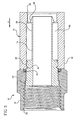
- Figure 1 is a perspective view of the coaxial cable connector of the present invention including a connector body having a movable collar, a post and a nut.
- Figure 2 is a cross-sectional view of the connector shown in Figure 1 with the movable collar in its first open position.
- Figure 3 is a cross-sectional view of the connector shown in Figure 1 with the movable collar in its second closed position.
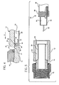
- Figure 4 is a detailed view of the cooperating detent structure shown in Figures 2 and 3.
- Figure 5 is an exploded cross-sectional view of the termination of a prepared coaxial cable with the connector of the present invention.
- Figure'6 is a perspective view of an alternative embodiment of the coaxial cable connector of the present invention shown in its initial supplied configuration including a connector body having a movable collar, a post and a nut.
- Figure 7 is a cross-sectional view of the connector shown in Figure 6.
- Figure 7a is an enlarged view of the temporary attachment of the collar to the post shown in Figure 7.
- Figure 8 is a cross-sectional view of the connector shown in Figure 6 with the movable collar in its first open position.
- Figure 9 is a cross-sectional view of the connector shown in Figure 6 with the movable collar in its second closed position.
- Figure 10 is a detailed view of the cooperating detent structure shown in Figures 7, 8 and 9.
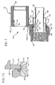
- Figure 11 is an exploded cross-sectional view of the termination of a prepared coaxial cable prior to insertion within the connector of the present invention.
- Figure 12 is an exploded cross-sectional view of the termination of a prepared coaxial cable after insertion within the connector of the present invention.
- Figure 13 is a cross-sectional view of another alternative embodiment of the present invention showing the collar in its first position.
- Figure 14 is a cross-sectional view of the alternative embodiment shown in Figure 13 showing the collar in its second or locked position.
-
- The present invention is directed to connectors for terminating coaxial cable. Coaxial connectors of this type are shown and described in commonly owned U.S. Patent No. 6,530,807 issued August 28, 2003, the disclosure of which is incorporated herein by reference.
- Referring to Figures 1-3, the
coaxial cable connector 10 of the present invention is shown. Contrary to the prior art connectors,connector 10 includes only three components: amovable collar 12; anannular post 14; and arotatable nut 16. Thecollar 12 is an elongate generally cylindrical member, which may be formed of metal or plastic, having one end movably coupled to thepost 14 and an opposite end for receiving a coaxial cable. Thenut 16 may be in any form, such as a hex nut, knurled nut, wing nut, etc., and is rotatably coupled to thepost 14 for providing mechanical attachment of the connector to an external device. A resilient sealing O-ring 18 may be positioned between thecollar 12, thepost 14 and thenut 16 at the rotatable juncture thereof to provide a water resistant seal thereat. - The
collar 12 includes acable receiving end 20 for insertably receiving a prepared end of a coaxial cable. Thenut 16 includes an internally threadedend extent 22 permitting screw threaded attachment of theconnector body 10 to the external device. Thecable receiving end 20 and the internally threadedend extension 22 define opposite ends of theconnector 10. - The
annular post 14 includes aflanged base portion 24, which provides for press-fit securement of the post within a post receiving space in thenut 16. Theannular post 14 further includes an elongatedannular shoulder portion 26 having an outer surface which provides for movable attachment of thecollar 12 to the post. Thepost 14 also includes an annulartubular extension 28 extending into the collar. The distal end of thetubular extension 28 includes a radially outwardly extending rampedflange portion 29 for compressing the outer jacket of the coaxial cable between theflange portion 29 and the internal diameter of thecollar 12 to secure the cable within the connector. As will be described in further detail hereinbelow, theextension 28 of thepost 14 and thecollar 12 define anannular chamber 30 for accommodating the jacket and shield of the inserted coaxial cable. - Opposite the
cable receiving end 20 of thecollar 12 is aforward end 32 which is movably coupled to the outer surface of theshoulder portion 26 of thepost 14. As will be described in further detail hereinbelow, theforward end 32 of thecollar 12 and theshoulder portion 26 of thepost 14 preferably include cooperative detent structure which allows for the movable connection of thecollar 12 to thepost 14 such that the collar is axially moveable along arrow A of Figures 2 and 3, towardsnut 16 from a first position shown in Figure 2, which loosely retains the cable within theconnector body 10, to a more forward second position shown in Figure 3, which secures the cable within the connector. - It is envisioned that other types of securing means may be utilized to movably couple the
collar 12 to theannular post 14. For example, thecollar 12 may be press-fit onto theshoulder portion 26 of thecollar 12 whereby the cable is locked in position by the friction fit between thepost 14 and thecollar 12 and between the post rampedflange 29 and the collar. Alternatively, thepost shoulder portion 26 and the internal diameter of thecollar 12 may be provided with mating cooperating threads for movably securing the collar to thepost 14 between its first and second position. - The
connector 10 of the present invention is constructed so as to be supplied in the assembled condition shown in Figure 2, wherein thecollar 12 is attached to thepost 14 in its first position. In such assembled condition, and as will be described in further detail hereinbelow, a coaxial cable may be inserted through therearward end 20 of thecollar 12. Thecollar 12 may then be moved from the first position loosely retaining the cable to the second position which is axially forward thereby locking the cable within the connector. - It is, however, contemplated that the
connector 10 may be provided with securing means such that thecollar 12 may be detachably coupled to thepost 14 and, in a manner which will be described in further detail hereinbelow, will allow the coaxial cable to be first inserted directly into thepost 14 unobstructed by the collar. Thereafter, thecollar 12, which has been earlier placed around the cable, may be reattached to thepost 14 where it can be moved from the first position to the second position locking the cable within the connector. - The cooperating detent structure mentioned above is but one exemplary structure employed to provide such attachment and movement of the
collar 12 to thepost 14. With additional reference to Figure 4, the cooperating detent structure is shown. Forward end 32 of thecollar 12 includes a radially inwardly directedannular rib 34 extending adjacent the distal end thereof.Rib 34 is defined by a rearwardly facingperpendicular wall 36 and a forwardly facing chamferedwall 38. The cooperating detent structure of the present invention further includes theshoulder portion 26 of thepost 14 formed to have two radially outwardly openingannular grooves rib 34 of thecollar 12. Thegrooves shoulder portion 26 of the post to define arearward groove 40 and aforward groove 41. Bothgrooves perpendicular wall 42 and a rearwardly facing chamferedwall 44, which respectively engage theperpendicular wall 36 and the chamferedwall 38 of thecollar rib 34. Where it is desired to have thecollar 12 detachable from thepost 14 when the collar is in its first position, it is preferable to eliminate theperpendicular wall 42 from therearward groove 40 and substitute a forwardly facing chamfered wall in its place. It is also contemplated to have the cooperating detent structure reversed, wherein an annular rib is provided on the outer surface of the post shoulder portion and a pair of axially spaced grooves are provided on the inner surface of the forward end of the collar. - As may be appreciated, the
post 14 may be inserted into theforward end 32 of thecollar 12 until therib 34 of the collar comes to rest within therearward groove 40 of thepost shoulder portion 26. To further facilitate initial assembly of thecollar 12 to thepost 14, the transition of the post between theshoulder portion 26 and the annulartubular extension 28 may also be provided with a rearwardly facing chamferedwall 46. Upon assembly of thecollar 12 to thepost 14, the forward chamferedwall 38 of thecollar rib 34 bears against the rearward chamferedwall 46 of the post shoulder portion transition. By its tubular shape, thecollar 12 will have some resiliency at itsforward end 32 which will allow therib 34 to ride over the rearward chamferedwall 46 of thepost shoulder portion 26 until the rib becomes lockingly resident within therearward groove 40 of the post shoulder portion. This defines the first position of thecollar 12. - As mentioned above, the cooperative detent structure of the present invention further includes a radially outwardly extending forward groove 41 formed on the
shoulder portion 26 of thepost 14 adjacent therearward groove 40. Upon continued coaxial movement of thecollar 12 along arrow A, therib 34 of the collar disengages therearward groove 40 and becomes resident within theforward groove 41 to define the second position of the collar which locks the collar in this position, thereby locking the cable within the connector. - Having described the components of the
connector 10 in detail, the use of the connector in terminating a coaxial cable may now be described with respect to Figure 5.Coaxial cable 50 includes aninner conductor 52 formed of copper or similar conductive material. Extending around theinner conductor 52 is aninsulator 54 formed of a suitably insulative plastic. Ametallic foil 53 is disposed over theinsulator 54 and ametallic shield 56 is positioned in surrounding relationship around the foil covered insulator. Covering themetallic shield 56 is anouter insulative jacket 58. -
Cable 50 is prepared in conventional fashion for termination by stripping backjacket 58 exposing an extent ofshield 56. A portion of the foil coveredinsulator 54 extends therefrom with an extent ofconductor 52 extending frominsulator 54. The preparation process includes folding back an end extent ofshield 56 aboutjacket 58. - As shown in exploded view in Figure 5,
cable 50 may be inserted into theconnector 10 with thecollar 12 coupled to thepost 14 as shown in Figure 2. In this technique, theprepared cable 50 is inserted through therearward end 20 of thecollar 12. Theextension 28 of thepost 14 is inserted between the foil coveredinsulator 54 and themetallic shield 56 such that the shield and thejacket 58 reside within theannular region 30 defined between thepost 14 and thecollar 12. When thecollar 12 is coupled to thepost 14 in the first position, as shown in Figures 2 and 5, sufficient clearance is provided between the collar and the post so thatextension 28 may be easily interposed between theinsulator 54 and theshield 56 of thecable 50. - Once the
cable 50 is properly inserted, thecollar 12 may be moved axially forward from the first position shown in Figures 2 and 5, to the second position shown in Figure 3. When thecollar 12 is moved axially forward, therib 34 formed in theforward end 32 of thecollar 12 disengages therearward groove 40 formed in theshoulder portion 26 of thepost 14. Such movement is facilitated by the forward facing chamferedwall 38 of thecollar rib 34 and the cooperating rearward facing chamferedwall 44 of therearward groove 40. Thecollar 12 is moved axially forward until thecollar rib 34 engages theforward groove 41 formed in theshoulder portion 26 of thepost 14. In this second position, thejacket 58 andshield 56 of thecable 50 begins to become compressively clamped within theannular region 30 between thepost 14 and thecollar 12. Theperpendicular walls rib 34 and theforward groove 41 help to maintain thecollar 12 in the second position with respect to thepost 14. A suitable tool may be used to effect movement of thecollar 12 from its first position to its secondposition securing cable 50 to theconnector 10. - As may be appreciated, proper insertion of the
cable 50 into theconnector body 10 requires that the cable be inserted in such a manner that theextension 28 of thepost 14 becomes resident between the foil coveredinsulator 54 and theshield 56. In certain installation settings, the installer may not have clear and convenient access when terminating thecable 50. Moreover, insertion may be rendered difficult by poor cable preparation, which may result in a frayed end. Therefore, it may be difficult for the installer to blindly insert thecable 50 through thecollar 12 and into theconnector body 10. In such situations, the present invention contemplates the ability to detachably remove thecollar 12 from thepost 14 so that the cable may be directly connected to theextension 28 of thepost 14. - In these situations, the
collar 12 is detachably removed from thepost 14 in a manner facilitated as above described. Thecollar 12 is then slipped over thecable 50 and moved to a convenient position along the cable length. The end of the foil coveredinsulator 54 may then be inserted directly into thepost extension 28 so that the extension is interposed between the foil coveredinsulator 54 and theshield 56. Thereafter, thecollar 12 may be brought up along thecable 50 and theforward end 32 of the collar may be slipped over theshoulder portion 26 of thepost 14. The respective chamferedwalls collar rib 34 and the shoulder portion transition facilitates insertion of thepost 14 into thecollar 12 so that the collar rib becomes resident within therearward groove 40 as shown in Figures 2 and 5 defining the first position. Thereafter, as described above, thecollar 12 may be moved from the first position shown in Figures 2 and 5 to a second position shown in Figure 3 where therib 34 becomes resident within theforward groove 41 of thepost 14 thereby locking thecable 50 in theconnector 10. - Alternatively, the
collar 12 may simply be removably press-fit over thepost shoulder portion 26 without the use of any detent structure. In this case, the same installation method would apply to secure the coaxial cable within the connector. - Referring now to Figures 6-12, an
alternative embodiment 110 of the coaxial cable connector formed in accordance with the present invention is shown. Figures 6, 7 and 7a show thecoaxial cable connector 110 of the alternative embodiment in its initial configuration as supplied to an installer.Connector 110 includes three major components: amovable collar 112; anannular post 114; and arotatable nut 116. Thecollar 112 is an elongate generally cylindrical member, which may be formed of metal or plastic, and having one end movably coupled to thepost 114 and an opposite end for receiving a coaxial cable. Thenut 116 may be in any form, such as a hex nut, knurled nut, wing nut, etc., and is rotatably coupled to thepost 114 for providing mechanical attachment of the connector to an external device. A resilient sealing O-ring 118 may be positioned between thecollar 112, thepost 114 and thenut 116 at the rotatable juncture thereof to provide a water resistant seal thereat. - The
collar 112 is initially temporarily attached to thepost 114 by adetachable arm 113 including aring 115 and aring extension 117. Thering 115 is sized to receive and be snugly fitted over ashoulder portion 126 of thepost 114. Thering 115 may take the form of a split-ring wherein aslot 119 breaks the continuity of the ring to facilitate easy attachment and detachment of thecollar 112 to thepost 114. With a split-ring arrangement, thecollar 112 may be attached and detached from thepost 114 in a direction perpendicular to the post axis, as opposed to being longitudinally slipped over the post shoulder section. - The
ring 115 further preferably includes a radially inwardly directedannular rib 119 defined by a rearwardly facingperpendicular wall 121 and a forwardly facing chamferedwall 123. Therib 119 of thering 115 engages a radially outwardly opening annularforward groove 141 formed in theshoulder portion 126 of thepost 114 to secure the ring to the post. With additional reference to Figure 10, theforward groove 141 preferably includes a forwardly facingperpendicular wall 142 and a rearwardly facing chamferedwall 144, which respectively engages theperpendicular wall 121 and thechamfered wall 123 of thering rib 119. - As may be appreciated, the
ring 115 may be longitudinally slipped over thepost 114 or, where the ring is a split-ring, it may be laterally snapped in place whereby therib 119 of the ring comes to rest within theforward groove 141 of thepost shoulder portion 126. To further facilitate initial assembly of thering 115 to thepost 114, thering rib 119 is provided with the forwardchamfered wall 123 which, when seated, bears against the rearward chamferedwall 144 of theforward groove 141. However, the rearward facingperpendicular wall 121 of thering rib 119 bearing against the forward facingperpendicular wall 142 of theforward groove 141 prevents inadvertent rearward axial movement of thering 115. - The
ring 115 is connected to thecollar 112 by a radially outwardly extendingring extension 117. Thering extension 117 preferably includes afrangible portion 125 disposed where the extension meets thecollar 112. Thefrangible portion 125 may include a perforation, slit, groove or other structure for permitting thering extension 117 to be easily and cleanly detached from thecollar 112. Once detached from thecollar 112, thedetachable arm 113, including thering 115 and thering extension 117, has no further use and may be discarded. Thecollar 112 is now preferably slipped over the end of a prepared coaxial cable or, alternatively, the collar may be attached first to thepost 114. - Referring additionally to Figures 8 and 9, the
collar 112 includes acable receiving end 120 for insertably receiving a prepared end of a coaxial cable. Thenut 116 includes an internally threadedend extent 122 permitting screw threaded attachment of theconnector body 110 to the external device. Thecable receiving end 120 and the internally threadedend extension 122 define opposite ends of theconnector 110. - The
annular post 114 includes aflanged base portion 124 which provides for press-fit securement of the post within a post receiving space in thenut 116. Theannular post 114 further includes an elongatedannular shoulder portion 126 having an outer surface, which provides for movable attachment of thecollar 112 to the post. However, in this embodiment, thepost 114 also includes anannular sleeve portion 127 extending rearwardly from the shoulder portion and an annulartubular extension 128 extending from within the sleeve portion into the collar. Thesleeve portion 127 and thetubular extension 128 of thepost 114 define anannular pocket 129 therebetween and thepost extension 128 and thecollar 112 define anannular chamber 130. The distal end of thetubular extension 128 includes a radially outwardly extending rampedflange portion 131 for compressing the outer jacket of the coaxial cable in theannular chamber 130 between the flange portion and the internal diameter of thecollar 112 to secure the cable within the connector. As will be described in further detail herein below, both thepocket 129 and thechamber 130 are designed for accommodating the jacket and shield of the inserted coaxial cable. - Opposite the
cable receiving end 120 of thecollar 112 is aforward end 132 which is movably coupled to the outer surface of theshoulder portion 126 of thepost 114. As discussed above, theforward end 132 of thecollar 112 and theshoulder portion 126 of thepost 114 preferably include cooperative detent structure which allows for the movable connection of thecollar 112 to thepost 114 such that the collar is axially moveable along arrow A of Figures 8-12, towardsnut 116 from a first position shown in Figure 8, which loosely retains the cable within theconnector body 110, to a more forward second position shown in Figure 9, which secures the cable within the connector. Alternatively, since the collar may first be slipped onto the cable before insertion of the cable into the post, only the second, locked position may be provided with cooperating structure to lock the collar in the closed position. - As mentioned above, the
connector 110 of the present invention is constructed so as to be supplied in the pre-assembled condition shown in Figures 6 and 7, wherein thecollar 112 is temporarily attached to thepost 114 by thedetachable arm 113. In a preferred method of installation, thecollar 112, which is still attached to thepost 114 in its pre-assembled condition, is slipped onto an end of aprepared cable 150. Once positioned on thecable 150, thecollar 112 is detached from thepost 114 via thefrangible arm 113. In this manner, there is less chance that the installer will drop or lose either of the two components of the connector assembly. After detaching thecollar 112 from such pre-assembled condition, and as will be described in further detail herein below, a coaxial cable may be inserted through therearward end 120 of thecollar 112 and connected directly to thepost 114. Thereafter, thecollar 112 may be attached to thepost 114 where it can be moved from the first position to the second position locking the cable within the connector. - With additional reference to Figure 10, the cooperating detent structure is shown. Forward end 132 of the
collar 112 includes a radially inwardly directedannular rib 134 extending adjacent the distal end thereof.Rib 134 is defined by a rearwardly facingperpendicular wall 136 and a forwardly facing chamferedwall 138. The cooperating detent structure of the present invention further includes theshoulder portion 126 of thepost 114 formed to have two radially outwardly openingannular grooves rib 134 of thecollar 112. Thegrooves shoulder portion 126 of the post to define arearward groove 140 and aforward groove 141. Bothgrooves perpendicular wall 142 and a rearwardly facing chamferedwall 144, which respectively engage theperpendicular wall 136 and thechamfered wall 138 of thecollar rib 134. Where it is desired to have thecollar 112 detachable from thepost 114 after the collar has been placed in its first position, it is preferable to eliminate theperpendicular wall 142 from therearward groove 140 and substitute a forwardly facing chamfered wall in its place. - As may be appreciated, the
forward end 132 of thecollar 112 may be fitted over thesleeve portion 127 of thepost 114 and slid forward until therib 134 of the collar comes to rest within therearward groove 140 of thepost shoulder portion 126. To facilitate such initial assembly of thecollar 112 to thepost 114, therib 134 is provided with a forward facing chamferedwall 138, as described above. By its tubular shape, thecollar 112 will have some resiliency at itsforward end 132 which will allow therib 134 to ride over thesleeve portion 127 of thepost 114 until the rib becomes lockingly resident within therearward groove 140 of thepost shoulder portion 126. This defines the first position of thecollar 112. - As mentioned above, the cooperative detent structure of the present invention further includes a radially outwardly extending forward groove 141 formed on the
shoulder portion 126 of thepost 114 adjacent therearward groove 140. Upon continued coaxial movement of thecollar 112 along arrow A, therib 134 of the collar disengages therearward groove 140 and becomes resident within theforward groove 141 to define the second position of the collar which locks the collar in this position, thereby locking the cable within the connector. - Referring to Figures 11 and 12,
coaxial cable 150 is prepared in conventional fashion for termination by stripping backjacket 158 exposing an extent ofshield 156. A portion of the foil coveredinsulator 154 extends therefrom with an extent ofconductor 152 extending frominsulator 154. The preparation process includes folding back an end extent ofshield 156 aboutjacket 158. - Again, proper insertion of the
cable 150 into theconnector body 110 requires that the cable be inserted in such a manner that theextension 128 of thepost 114 becomes resident between the foil coveredinsulator 154 and theshield 156. Thus, as shown in exploded view in Figures 11 and 12, thecollar 112 of theconnector assembly 110 is preferably slipped over the end of acoaxial cable 150 and moved to a convenient position along the cable length prior to connecting the cable to thepost 114. Thepost 114 may then be detached from thearm ring 115 and thefrangible arm extension 117 may be detached from thecollar 112. If desired, the installer may detach the collar prior to slipping the collar on the cable depending upon the installation. In either event, thecollar 112 is oriented on thecable 150 so that theforward end 132 of the collar faces the end of the cable which will be prepared and inserted into thepost 114. The end of the foil coveredinsulator 154 may then be inserted directly into thepost extension 128 so that the extension is interposed between the foil coveredinsulator 154 and theshield 156. Thecable 150 is then further pushed forward whereby the folded-over portion of theshield 156 is inserted into thepost pocket 129 defined between the post sleeve portion and thepost tubular extension 128, as shown in Figure 12. The folded-over portion of theshield 156 that becomes resident within thepost pocket 129 is now protected from damage which may occur upon further assembly of the connector. In particular, thepost pocket 129 protects the exposed portion of theshield 156 from damage that may be caused by thecollar 112 as it is moved forward on thepost 114 to lock thecable 150 within theconnector 110 as described further below. - Thereafter, the
collar 112 may be brought up along thecable 150 and theforward end 132 of the collar may be slipped forward over thesleeve portion 127 and theshoulder portion 126 of thepost 114 until thecollar rib 134 becomes resident within therearward groove 140 as shown in Figures 8 and 9 defining the first position. As previously mentioned, it is also contemplated that no structure may be necessary to hold thecollar 112 in the first position in this alternative embodiment. - Once the
cable 150 is properly inserted and thecollar 112 is set in its first position, the collar is then further moved axially forward from the first position shown in Figures 8 and 10, to the second position shown in Figure 9. When thecollar 112 is moved axially forward, therib 134 formed in theforward end 132 of thecollar 112 disengages therearward groove 140 formed in theshoulder portion 126 of thepost 114. Such movement is facilitated by the forward facing chamferedwall 138 of thecollar rib 134 and the cooperating rearward facing chamferedwall 144 of therearward groove 140. Thecollar 112 is moved axially forward until thecollar rib 134 engages theforward groove 141 formed in theshoulder portion 126 of thepost 114. A suitable tool may be used to effect movement of thecollar 112 from its first position to its second position securing thecable 150 to theconnector 110. In this second position, thejacket 158 of thecable 150 becomes compressively clamped within theannular chamber 130 between theextension 128 of thepost 114 and thecollar 112. Also, theperpendicular walls rib 134 and theforward groove 141 help to maintain thecollar 112 in the second position with respect to thepost 114 thereby locking thecable 150 within theconnector 110. - Alternatively, the
collar 112 may first be assembled to thepost 114 in its first position as shown in Figures 8 and 10 and thecable 150 may be subsequently inserted into the collar. In this scenario, theprepared cable 150 is inserted through therearward end 120 of thecollar 112 while the collar is connected to thepost 114 in its first position. Theextension 128 of thepost 114 is inserted between theinsulator 154 and themetallic shield 156 such that the folded-over portion of the shield resides within thepost pocket 129 defined between thepost sleeve portion 127 and thetube extension 128 and theuncovered jacket 158 resides within theannular region 130 defined between thepost 114 and thecollar 112. When thecollar 112 is coupled to thepost 114 in the first position, as shown in Figures 8 and 10, sufficient clearance is provided between the collar and the post so thatextension 128 may be easily interposed between theinsulator 154 and theshield 156 of thecable 150. - Thereafter, as described above, the
collar 112 may be moved from the first position shown in Figures 8 and 10 to a second position shown in Figure 9 where therib 134 becomes resident within theforward groove 141 of thepost 114 thereby locking thecable 150 within theconnector 110. - Referring now to Figures 13 and 14, still another alternative embodiment of the
coaxial cable connector 200 of the present invention is shown. Theconnector 200 includes the same three major components: amovable collar 202; anannular post 204; and arotatable nut 206. However, in this embodiment, themovable collar 202 is coupled to thenut 206 in a first position and is movable to a second position, wherein the collar is coupled to thepost 204. - In particular, the
nut 206 in this embodiment extends further rearwardly and includes a rearwardinterior surface 208 having structure to engage thecollar 202 in a first position. Thepost 204 again includes anaxial bore 210 therein, ashoulder portion 212 defined by anouter surface 214 and atubular extension 216 extending axially rearwardly from the shoulder portion. However, in this embodiment, theouter surface 214 of thepost shoulder portion 212 includes structure for coupling thecollar 202 only in its second position. To accomplish this, theforward end 218 of the collar includes structure on both itsouter surface 220 and itsinner surface 222 to respectively engage theinner surface 208 of thenut 206 and theouter surface 214 of thepost shoulder portion 212. - Again, the securing means for coupling the
collar 202 to the other connector components preferably takes the form of cooperating detent structure, wherein theouter surface 220 of thecollar 202 includes an outwardly extendingannular rib 224 formed thereon and theinner surface 222 of the collar includes an inwardly extendingannular rib 226 formed thereon. Conversely, theinner surface 208 of thenut 206 includes a firstannular groove 228 formed thereon and theouter surface 214 of thepost shoulder portion 212 includes a secondannular groove 230 formed thereon. - As described above, the
annular ribs grooves annular ribs 224 are preferably defined by a rearwardly facingperpendicular wall 232 and a forwardly facing chamferedwall 234 and theannular grooves perpendicular wall 236 and a rearwardly facing chamferedwall 238 to permit only forward movement of the collar. Moreover, thepost shoulder portion 212 of this embodiment may also include a rearwardly facing chamferedwall 240 at a transition between the shoulder portion and thetubular extension 216 to facilitate attachment of thecollar 202 to the post. Finally, the post may further include an annular sleeve portion (not shown in Figures 13 and 14) extending rearwardly from theshoulder portion 212, which defines an annular pocket between the sleeve portion and the tubular extension, as shown in Figures 6-12. - Use of the
cable connector 200 shown in Figures 13 and 14 is similar to that described above. Specifically, a coaxial cable may be inserted through therearward end 242 of thecollar 202 and the collar may then be moved from its first position, as shown in Figure 13, thereby loosely retaining the cable, to an axially forward second position, as shown in Figure 14, thereby locking the cable within the connector. - Although the illustrative embodiments of the present invention have been described herein with reference to the accompanying drawings, it is to be understood that the invention is not limited to those precise embodiments, and that various other changes and modifications may be effected therein by one skilled in the art without departing from the scope or spirit of the invention.
- Various changes to the foregoing described and shown structures will now be evident to those skilled in the art. Accordingly, the particularly disclosed scope of the invention is set forth in the following claims.
Claims (30)
- A coaxial cable connector comprising:an annular post defining an axial bore therein, said post having a shoulder portion including an outer surface and a tubular extension extending axially from said shoulder portion;a cylindrical collar having a forward end movably coupled to said outer surface of said post shoulder portion for movement between a first open position to receive a prepared coaxial cable and a second closed position to lock the cable in the connector; anda nut rotatably coupled to said post shoulder portion.
- A coaxial cable connector as defined in claim 1, further comprising a sealing ring disposed between said post, said collar and said nut.
- A coaxial cable connector as defined in claim 1 or claim 2, wherein said post shoulder portion includes a flanged base portion for securing said post in said nut.
- A coaxial cable connector as defined in any one of claims 1 to 3, wherein said outer surface of said post shoulder portion and said forward end of said collar include cooperating detent structure for permitting axial movement of said collar and said post from said first position to said second position.
- A coaxial cable connector as defined in any one of claims 1 to 4, wherein said cooperating detent structure comprises an annular rib formed on one of said forward end of said collar and said outer surface of said post shoulder portion and two axially spaced annular grooves formed on the other of said forward end of said collar and said outer surface of said post shoulder portion.
- A coaxial cable connector as defined in claim 5, wherein said annular rib is provided on said collar and is defined by rearwardly facing perpendicular wall and a forwardly facing chamfered wall and said grooves are provided on said outer surface of said post shoulder portion and are defined by a forwardly facing perpendicular wall and a rearwardly facing chamfered wall to permit only forward movement of said collar on said post.
- A coaxial cable connector as defined in any one of claims 1 to 6, wherein said collar is movable with respect to said post from a first position for loosely retaining a coaxial cable within the connector to a forward second position for securing the cable within the connector.
- A coaxial cable connector as defined in any one of claims 1 to 7, wherein said forward end of said collar is press-fit on said outer surface of said post shoulder portion.
- A coaxial cable connector as defined in any one of claims 1 to 7, wherein said forward end of said collar is threadably engaged with said outer surface of said post shoulder portion.
- A coaxial cable connector as defined in any one of claims 1 to 9, wherein said collar is detachably coupled to said post.
- A coaxial cable connector as defined in any one of claims 1 to 10, wherein said collar includes a detachable arm extending outwardly therefrom for temporarily attaching said collar to said post in an initial configuration.
- A coaxial cable connector as defined in claim 11, wherein said detachable arm comprises a ring extension extending radially outwardly from said collar and a ring disposed at an end of said ring extension for attaching said collar to said post, said ring being sized to be snugly fit on said outer surface of said post shoulder portion.
- A coaxial cable connector as defined in claim 12, wherein said ring includes a slot breaking the continuity of said ring for facilitating perpendicular attachment of said ring to said post shoulder portion.
- A coaxial cable connector as defined in claim 12, wherein said outer surface of said post shoulder portion and said ring include cooperating detent structure for facilitating attachment of said ring to said post shoulder portion.
- A coaxial cable connector as defined in claim 12, wherein said ring extension includes a frangible portion disposed where the extension meets the collar.
- A method for terminating a coaxial cable within a coaxial cable connector, the method comprising the steps of:inserting a prepared end of a coaxial cable into a rearward end of a cylindrical collar of the connector, said collar having a forward end movably coupled to an outer surface of an annular post of the connector; andmoving said collar axially forward on said outer surface of said annular post to a locked position wherein said cable is secured within said connector.
- A method as defined in claim 16, further comprising the steps of:detaching an arm of said collar from said outer surface of said annular post;detaching said arm from said collar; andmovably coupling said forward end of said collar to said outer surface of said annular post.
- A method for terminating a coaxial cable within a coaxial cable connector, the method comprising the steps of:inserting a prepared end of a coaxial cable into a rearward end of a cylindrical collar of the connector;movably coupling a forward end of said collar to an outer surface of an annular post of the connector; andmoving said collar axially forward on said outer surface of said annular post to a locked position wherein the cable is secured within the connector.
- A method as defined in claim 16 or claim 18, wherein during said moving step, the cable end is compressed within an annular chamber formed between said collar and a tubular extension of said post extending axially rearward from said shoulder portion.
- A method as defined in claim 16 or claim 18, wherein said moving step comprises moving said collar from a first position wherein said cable is loosely retained within the connector to said locked position wherein said cable is secured within the connector.
- A method as defined in claim 20, wherein said moving step further comprises the step of disengaging a rib formed on one of said forward end of said collar and said outer surface of said annular post from a first groove formed on the other said forward end of said collar and said outer surface of said annular post and engaging said rib in a second groove formed on the other of said forward end of said collar and said outer surface of said annular post.
- A method as defined in claim 18, further comprising the steps of:detaching an arm of said collar from said outer surface of said annular post prior to movably coupling said collar to said post; anddetaching said arm from said collar.
- A method as defined in claim 16 or claim 18, wherein said inserting step includes the step of inserting a shield portion of the prepared end of the coaxial cable into an annular pocket defined between an annular sleeve portion and a tubular extension of said annular post.
- A coaxial cable connector comprising:an annular post defining an axial bore therein, said post having a shoulder portion including an outer surface and a tubular extension extending axially from said shoulder portion;a nut rotatably coupled to said post shoulder portion, said nut having an interior surface; anda cylindrical collar having a forward end movably coupled to said interior surface of said rotatable nut in a first open position to receive a prepared coaxial cable, said collar being movable forward to a second closed position securing the cable in said connector, wherein said collar is coupled to said outer surface of said annular post.
- A coaxial cable connector as defined in claim 1 or claim 31, wherein said collar and said post tubular extension define an annular chamber therebetween.
- A coaxial cable connector as defined in claim 24 or claim 25, wherein said interior surface of said nut, said outer surface of said post shoulder portion and said forward end of said collar include cooperating detent structure for permitting said forward movable connection of said collar and said post.
- A coaxial cable connector as defined in claim 26, wherein said cooperating detent structure comprises an outwardly extending annular rib formed on an outer surface of said forward end of said collar, an inwardly extending annular rib formed on an inner surface of said forward end of said collar, a first annular groove formed on said inner surface of said nut and a second annular groove formed on said outer surface of said post shoulder portion.
- A coaxial cable connector as defined in claim 27, wherein said annular ribs are defined by a rearwardly facing perpendicular wall and a forwardly facing chamfered wall and said annular grooves are defined by a forwardly facing perpendicular wall and a rearwardly chamfered wall to permit only forward movement of said collar.
- A coaxial cable connector as defined in any one of claims 1 to 9 or 24 to 28, wherein said post shoulder portion includes a rearwardly facing chamfered wall at a transition between said shoulder portion and said tubular extension to facilitate attachment of said collar to said post.
- A coaxial cable connector as defined in any one of claims 1 to 17 or 24 to 29, wherein said post further includes an annular sleeve portion extending rearwardly from said shoulder portion, said sleeve portion and said tubular extension defining an annular pocket therebetween.
Applications Claiming Priority (4)
| Application Number | Priority Date | Filing Date | Title |
|---|---|---|---|
| US56295204P | 2004-04-16 | 2004-04-16 | |
| US56295304P | 2004-04-16 | 2004-04-16 | |
| US562952P | 2004-04-16 | ||
| US562953P | 2004-04-16 |
Publications (2)
| Publication Number | Publication Date |
|---|---|
| EP1587181A2 true EP1587181A2 (en) | 2005-10-19 |
| EP1587181A3 EP1587181A3 (en) | 2006-04-05 |
Family
ID=34940840
Family Applications (1)
| Application Number | Title | Priority Date | Filing Date |
|---|---|---|---|
| EP05252347A Withdrawn EP1587181A3 (en) | 2004-04-16 | 2005-04-15 | Coaxial cable connector |
Country Status (6)
| Country | Link |
|---|---|
| US (2) | US7241172B2 (en) |
| EP (1) | EP1587181A3 (en) |
| AR (2) | AR048608A1 (en) |
| BR (1) | BRPI0501318A (en) |
| CA (1) | CA2504457C (en) |
| MX (1) | MXPA05004120A (en) |
Cited By (2)
| Publication number | Priority date | Publication date | Assignee | Title |
|---|---|---|---|---|
| EP1758205A3 (en) * | 2005-08-23 | 2008-04-23 | Thomas & Betts International, Inc. | Coaxial cable connector with friction-fit sleeve |
| EP2933881A1 (en) * | 2014-04-15 | 2015-10-21 | IMS Connector Systems GmbH | Hf connector |
Families Citing this family (78)
| Publication number | Priority date | Publication date | Assignee | Title |
|---|---|---|---|---|
| US8157589B2 (en) | 2004-11-24 | 2012-04-17 | John Mezzalingua Associates, Inc. | Connector having a conductively coated member and method of use thereof |
| US7114990B2 (en) | 2005-01-25 | 2006-10-03 | Corning Gilbert Incorporated | Coaxial cable connector with grounding member |
| MX2008012578A (en) * | 2006-03-29 | 2009-04-15 | Corning Gilbert Inc | Coaxial connector and coaxial cable connector assembly and related method. |
| US7645163B2 (en) * | 2006-09-13 | 2010-01-12 | John Mezzalingua Associates, Inc. | Step up pin for coax cable connector |
| US7351099B1 (en) * | 2006-09-13 | 2008-04-01 | John Mezzalingua Associates, Inc. | Step up pin for coax cable connector |
| US7946885B2 (en) * | 2006-09-13 | 2011-05-24 | John Mezzalingua Associates, Inc. | Step up pin for coax cable connector |
| US8038471B2 (en) * | 2007-10-05 | 2011-10-18 | John Mezzalingua Associates, Inc. | Coaxial cable connector |
| USD607826S1 (en) | 2007-11-15 | 2010-01-12 | Ds Engineering, Llc | Non-compressed coaxial cable F-connector with tactile surfaces |
| USD607827S1 (en) | 2007-11-15 | 2010-01-12 | Ds Engineering, Llc | Compressed coaxial cable F-connector with tactile surfaces |
| USD607828S1 (en) | 2007-11-19 | 2010-01-12 | Ds Engineering, Llc | Ringed compressed coaxial cable F-connector |
| USD608294S1 (en) | 2007-11-19 | 2010-01-19 | Ds Engineering, Llc | Ringed non-compressed coaxial cable F-connector |
| USD607829S1 (en) | 2007-11-26 | 2010-01-12 | Ds Engineering, Llc | Ringed, compressed coaxial cable F-connector with tactile surfaces |
| USD607830S1 (en) | 2007-11-26 | 2010-01-12 | Ds Engineering, Llc | Ringed, non-composed coaxial cable F-connector with tactile surfaces |
| US8834200B2 (en) | 2007-12-17 | 2014-09-16 | Perfectvision Manufacturing, Inc. | Compression type coaxial F-connector with traveling seal and grooved post |
| US7841896B2 (en) | 2007-12-17 | 2010-11-30 | Ds Engineering, Llc | Sealed compression type coaxial cable F-connectors |
| US8371874B2 (en) | 2007-12-17 | 2013-02-12 | Ds Engineering, Llc | Compression type coaxial cable F-connectors with traveling seal and barbless post |
| US7513795B1 (en) | 2007-12-17 | 2009-04-07 | Ds Engineering, Llc | Compression type coaxial cable F-connectors |
| US7452237B1 (en) | 2008-01-31 | 2008-11-18 | John Mezzalingua Associates, Inc. | Coaxial cable compression connector |
| US7933165B2 (en) * | 2008-09-03 | 2011-04-26 | Fairfield Industries Incorporated | Connector for seismic cable |
| US8226328B2 (en) | 2008-09-03 | 2012-07-24 | Fairfield Industries Incorporated | Seismic cable with adjustable buoyancy |
| US8113875B2 (en) | 2008-09-30 | 2012-02-14 | Belden Inc. | Cable connector |
| US8025518B2 (en) | 2009-02-24 | 2011-09-27 | Corning Gilbert Inc. | Coaxial connector with dual-grip nut |
| US7824216B2 (en) | 2009-04-02 | 2010-11-02 | John Mezzalingua Associates, Inc. | Coaxial cable continuity connector |
| EP2429630B1 (en) * | 2009-04-30 | 2017-10-25 | Medtronic, Inc | A shielded implantable medical lead with reduced torsional stiffness |
| US8287320B2 (en) | 2009-05-22 | 2012-10-16 | John Mezzalingua Associates, Inc. | Coaxial cable connector having electrical continuity member |
| US9017101B2 (en) | 2011-03-30 | 2015-04-28 | Ppc Broadband, Inc. | Continuity maintaining biasing member |
| US8444445B2 (en) | 2009-05-22 | 2013-05-21 | Ppc Broadband, Inc. | Coaxial cable connector having electrical continuity member |
| US9570845B2 (en) | 2009-05-22 | 2017-02-14 | Ppc Broadband, Inc. | Connector having a continuity member operable in a radial direction |
| US8573996B2 (en) | 2009-05-22 | 2013-11-05 | Ppc Broadband, Inc. | Coaxial cable connector having electrical continuity member |
| US8016613B2 (en) * | 2009-11-12 | 2011-09-13 | Amphenol Corporation | Coaxial connector with locking sleeve for terminating cable |
| GB201006063D0 (en) * | 2010-04-12 | 2010-05-26 | Technetix Group Ltd | Cable connector |
| TWI549386B (en) * | 2010-04-13 | 2016-09-11 | 康寧吉伯特公司 | Coaxial connector with inhibited ingress and improved grounding |
| US8888526B2 (en) | 2010-08-10 | 2014-11-18 | Corning Gilbert, Inc. | Coaxial cable connector with radio frequency interference and grounding shield |
| US8556656B2 (en) | 2010-10-01 | 2013-10-15 | Belden, Inc. | Cable connector with sliding ring compression |
| US8167646B1 (en) * | 2010-10-18 | 2012-05-01 | John Mezzalingua Associates, Inc. | Connector having electrical continuity about an inner dielectric and method of use thereof |
| US8323053B2 (en) | 2010-10-18 | 2012-12-04 | John Mezzalingua Associates, Inc. | Connector having a constant contact nut |
| US8167635B1 (en) | 2010-10-18 | 2012-05-01 | John Mezzalingua Associates, Inc. | Dielectric sealing member and method of use thereof |
| US20120091249A1 (en) | 2010-10-19 | 2012-04-19 | John Mezzalingua Associates, Inc. | Cable carrying case |
| TWI558022B (en) | 2010-10-27 | 2016-11-11 | 康寧吉伯特公司 | Push-on cable connector with a coupler and retention and release mechanism |
| US8337229B2 (en) | 2010-11-11 | 2012-12-25 | John Mezzalingua Associates, Inc. | Connector having a nut-body continuity element and method of use thereof |
| US8414322B2 (en) | 2010-12-14 | 2013-04-09 | Ppc Broadband, Inc. | Push-on CATV port terminator |
| US8398421B2 (en) | 2011-02-01 | 2013-03-19 | John Mezzalingua Associates, Inc. | Connector having a dielectric seal and method of use thereof |
| US8157588B1 (en) | 2011-02-08 | 2012-04-17 | Belden Inc. | Cable connector with biasing element |
| US8342879B2 (en) | 2011-03-25 | 2013-01-01 | John Mezzalingua Associates, Inc. | Coaxial cable connector |
| US8465322B2 (en) | 2011-03-25 | 2013-06-18 | Ppc Broadband, Inc. | Coaxial cable connector |
| US8366481B2 (en) | 2011-03-30 | 2013-02-05 | John Mezzalingua Associates, Inc. | Continuity maintaining biasing member |
| US8388377B2 (en) | 2011-04-01 | 2013-03-05 | John Mezzalingua Associates, Inc. | Slide actuated coaxial cable connector |
| US8348697B2 (en) | 2011-04-22 | 2013-01-08 | John Mezzalingua Associates, Inc. | Coaxial cable connector having slotted post member |
| US9711917B2 (en) | 2011-05-26 | 2017-07-18 | Ppc Broadband, Inc. | Band spring continuity member for coaxial cable connector |
| WO2012162431A2 (en) | 2011-05-26 | 2012-11-29 | Belden Inc. | Coaxial cable connector with conductive seal |
| US8758050B2 (en) | 2011-06-10 | 2014-06-24 | Hiscock & Barclay LLP | Connector having a coupling member for locking onto a port and maintaining electrical continuity |
| US8591244B2 (en) | 2011-07-08 | 2013-11-26 | Ppc Broadband, Inc. | Cable connector |
| US9190744B2 (en) | 2011-09-14 | 2015-11-17 | Corning Optical Communications Rf Llc | Coaxial cable connector with radio frequency interference and grounding shield |
| US20130072057A1 (en) | 2011-09-15 | 2013-03-21 | Donald Andrew Burris | Coaxial cable connector with integral radio frequency interference and grounding shield |
| US9908737B2 (en) | 2011-10-07 | 2018-03-06 | Perfectvision Manufacturing, Inc. | Cable reel and reel carrying caddy |
| US9147955B2 (en) | 2011-11-02 | 2015-09-29 | Ppc Broadband, Inc. | Continuity providing port |
| US9190773B2 (en) | 2011-12-27 | 2015-11-17 | Perfectvision Manufacturing, Inc. | Socketed nut coaxial connectors with radial grounding systems for enhanced continuity |
| US9362634B2 (en) | 2011-12-27 | 2016-06-07 | Perfectvision Manufacturing, Inc. | Enhanced continuity connector |
| US9136654B2 (en) | 2012-01-05 | 2015-09-15 | Corning Gilbert, Inc. | Quick mount connector for a coaxial cable |
| US9407016B2 (en) | 2012-02-22 | 2016-08-02 | Corning Optical Communications Rf Llc | Coaxial cable connector with integral continuity contacting portion |
| US9287659B2 (en) | 2012-10-16 | 2016-03-15 | Corning Optical Communications Rf Llc | Coaxial cable connector with integral RFI protection |
| US9147963B2 (en) | 2012-11-29 | 2015-09-29 | Corning Gilbert Inc. | Hardline coaxial connector with a locking ferrule |
| US9153911B2 (en) | 2013-02-19 | 2015-10-06 | Corning Gilbert Inc. | Coaxial cable continuity connector |
| US9172154B2 (en) | 2013-03-15 | 2015-10-27 | Corning Gilbert Inc. | Coaxial cable connector with integral RFI protection |
| US10290958B2 (en) | 2013-04-29 | 2019-05-14 | Corning Optical Communications Rf Llc | Coaxial cable connector with integral RFI protection and biasing ring |
| DK3000154T3 (en) | 2013-05-20 | 2019-07-22 | Corning Optical Comm Rf Llc | COAXIAL CABLE CONNECTOR WITH INTEGRAL RFI PROTECTION |
| US9548557B2 (en) | 2013-06-26 | 2017-01-17 | Corning Optical Communications LLC | Connector assemblies and methods of manufacture |
| US9048599B2 (en) | 2013-10-28 | 2015-06-02 | Corning Gilbert Inc. | Coaxial cable connector having a gripping member with a notch and disposed inside a shell |
| US9548572B2 (en) | 2014-11-03 | 2017-01-17 | Corning Optical Communications LLC | Coaxial cable connector having a coupler and a post with a contacting portion and a shoulder |
| US9590287B2 (en) | 2015-02-20 | 2017-03-07 | Corning Optical Communications Rf Llc | Surge protected coaxial termination |
| US10033122B2 (en) | 2015-02-20 | 2018-07-24 | Corning Optical Communications Rf Llc | Cable or conduit connector with jacket retention feature |
| US9564695B2 (en) | 2015-02-24 | 2017-02-07 | Perfectvision Manufacturing, Inc. | Torque sleeve for use with coaxial cable connector |
| US10211547B2 (en) | 2015-09-03 | 2019-02-19 | Corning Optical Communications Rf Llc | Coaxial cable connector |
| US9525220B1 (en) | 2015-11-25 | 2016-12-20 | Corning Optical Communications LLC | Coaxial cable connector |
| US10135176B1 (en) * | 2018-03-23 | 2018-11-20 | Cheng Pu Electric Co., Ltd. | Coaxial cable connector |
| US12034264B2 (en) | 2021-03-31 | 2024-07-09 | Corning Optical Communications Rf Llc | Coaxial cable connector assemblies with outer conductor engagement features and methods for using the same |
| CN113511181B (en) * | 2021-06-02 | 2024-02-27 | 北京汽车集团越野车有限公司 | Brake hard tube limiting device |
| CN117220216B (en) * | 2023-11-08 | 2024-02-02 | 国网山东省电力公司阳信县供电公司 | Antitheft cable sleeve |
Citations (5)
| Publication number | Priority date | Publication date | Assignee | Title |
|---|---|---|---|---|
| US5470257A (en) * | 1994-09-12 | 1995-11-28 | John Mezzalingua Assoc. Inc. | Radial compression type coaxial cable end connector |
| US6089913A (en) * | 1996-11-12 | 2000-07-18 | Holliday; Randall A. | End connector and crimping tool for coaxial cable |
| US6217383B1 (en) * | 2000-06-21 | 2001-04-17 | Holland Electronics, Llc | Coaxial cable connector |
| WO2001086756A1 (en) * | 2000-05-10 | 2001-11-15 | Thomas & Betts International, Inc. | Coaxial connector having detachable locking sleeve |
| US6425782B1 (en) * | 2000-11-16 | 2002-07-30 | Michael Holland | End connector for coaxial cable |
Family Cites Families (153)
| Publication number | Priority date | Publication date | Assignee | Title |
|---|---|---|---|---|
| US1667485A (en) | 1927-08-25 | 1928-04-24 | Leo O Smith | Connecter |
| GB524004A (en) | 1939-01-19 | 1940-07-26 | Cecil Oswald Browne | Improvements in or relating to plug and socket connections |
| US2549647A (en) | 1946-01-22 | 1951-04-17 | Wilfred J Turenne | Conductor and compressible insert connector means therefor |
| US2544654A (en) * | 1947-05-01 | 1951-03-13 | Dancyger Mfg Company | Shield for electric plugs |
| US3076168A (en) | 1960-03-07 | 1963-01-29 | Hellermann Ltd | Sealed plug and socket assemblies |
| US3184706A (en) | 1962-09-27 | 1965-05-18 | Itt | Coaxial cable connector with internal crimping structure |
| US3292136A (en) | 1964-10-01 | 1966-12-13 | Gremar Mfg Co Inc | Coaxial connector |
| US3275913A (en) | 1964-11-20 | 1966-09-27 | Lrc Electronics Inc | Variable capacitor |
| US3350677A (en) | 1965-03-30 | 1967-10-31 | Elastic Stop Nut Corp | Telescope waterseal connector |
| US3355698A (en) | 1965-04-28 | 1967-11-28 | Amp Inc | Electrical connector |
| US3373243A (en) | 1966-06-06 | 1968-03-12 | Bendix Corp | Electrical multiconductor cable connecting assembly |
| US3475545A (en) | 1966-06-28 | 1969-10-28 | Amp Inc | Connector for metal-sheathed cable |
| NL137270C (en) | 1966-07-26 | |||
| US3537065A (en) | 1967-01-12 | 1970-10-27 | Jerrold Electronics Corp | Multiferrule cable connector |
| CH472790A (en) | 1967-01-14 | 1969-05-15 | Satra Ets | Watertight socket and method for its realization |
| US3448430A (en) | 1967-01-23 | 1969-06-03 | Thomas & Betts Corp | Ground connector |
| US3498647A (en) | 1967-12-01 | 1970-03-03 | Karl H Schroder | Connector for coaxial tubes or cables |
| US3533051A (en) | 1967-12-11 | 1970-10-06 | Amp Inc | Coaxial stake for high frequency cable termination |
| US3544705A (en) | 1968-11-18 | 1970-12-01 | Jerrold Electronics Corp | Expandable cable bushing |
| US3629792A (en) | 1969-01-28 | 1971-12-21 | Bunker Ramo | Wire seals |
| US3564487A (en) | 1969-02-03 | 1971-02-16 | Itt | Contact member for electrical connector |
| US3633150A (en) | 1970-04-08 | 1972-01-04 | Edward Swartz | Watertight electric receptacle connector |
| US3671922A (en) | 1970-08-07 | 1972-06-20 | Bunker Ramo | Push-on connector |
| US3668612A (en) | 1970-08-07 | 1972-06-06 | Lindsay Specialty Prod Ltd | Cable connector |
| US3710005A (en) | 1970-12-31 | 1973-01-09 | Mosley Electronics Inc | Electrical connector |
| US3694792A (en) | 1971-01-13 | 1972-09-26 | Wall Able Mfg Corp | Electrical terminal clamp |
| GB1348806A (en) | 1971-05-20 | 1974-03-27 | C S Antennas Ltd | Coaxial connectors |
| US3778535A (en) | 1972-05-12 | 1973-12-11 | Amp Inc | Coaxial connector |
| US3781762A (en) | 1972-06-26 | 1973-12-25 | Tidal Sales Corp | Connector assembly |
| DE2260734C3 (en) | 1972-12-12 | 1984-09-20 | Georg Dr.-Ing. 8152 Feldkirchen-Westerham Spinner | RF coaxial connector |
| CA1009719A (en) | 1973-01-29 | 1977-05-03 | Harold G. Hutter | Coaxial electrical connector |
| FR2219553B1 (en) | 1973-02-26 | 1977-07-29 | Cables De Lyon Geoffroy Delore | |
| US3845453A (en) | 1973-02-27 | 1974-10-29 | Bendix Corp | Snap-in contact assembly for plug and jack type connectors |
| US3846738A (en) | 1973-04-05 | 1974-11-05 | Lindsay Specialty Prod Ltd | Cable connector |
| DE2331610C2 (en) | 1973-06-20 | 1987-03-26 | Georg Dr.-Ing. 8152 Feldkirchen-Westerham Spinner | Cable connector for fully insulated coaxial cables |
| US3910673A (en) | 1973-09-18 | 1975-10-07 | Us Energy | Coaxial cable connectors |
| US3836700A (en) | 1973-12-06 | 1974-09-17 | Alco Standard Corp | Conduit coupling |
| US3879102A (en) | 1973-12-10 | 1975-04-22 | Gamco Ind Inc | Entrance connector having a floating internal support sleeve |
| DE2421321C3 (en) | 1974-05-02 | 1978-05-11 | Georg Dipl.-Ing. Dr.-Ing. 8152 Feldkirchen-Westerham Spinner | Sealed coaxial connector |
| US3985418A (en) | 1974-07-12 | 1976-10-12 | Georg Spinner | H.F. cable socket |
| US3980805A (en) | 1975-03-31 | 1976-09-14 | Bell Telephone Laboratories, Incorporated | Quick release sleeve fastener |
| US4168921A (en) | 1975-10-06 | 1979-09-25 | Lrc Electronics, Inc. | Cable connector or terminator |
| US4053200A (en) | 1975-11-13 | 1977-10-11 | Bunker Ramo Corporation | Cable connector |
| US4126372A (en) | 1976-06-25 | 1978-11-21 | Bunker Ramo Corporation | Outer conductor attachment apparatus for coaxial connector |
| US4046451A (en) | 1976-07-08 | 1977-09-06 | Andrew Corporation | Connector for coaxial cable with annularly corrugated outer conductor |
| US4059330A (en) | 1976-08-09 | 1977-11-22 | John Schroeder | Solderless prong connector for coaxial cable |
| US4070751A (en) | 1977-01-12 | 1978-01-31 | Amp Incorporated | Method of making a coaxial connector |
| US4093335A (en) | 1977-01-24 | 1978-06-06 | Automatic Connector, Inc. | Electrical connectors for coaxial cables |
| US4150250A (en) | 1977-07-01 | 1979-04-17 | General Signal Corporation | Strain relief fitting |
| JPS5744731Y2 (en) | 1978-01-26 | 1982-10-02 | ||
| US4156554A (en) | 1978-04-07 | 1979-05-29 | International Telephone And Telegraph Corporation | Coaxial cable assembly |
| US4165554A (en) | 1978-06-12 | 1979-08-28 | Faget Charles J | Hand-held portable calculator assembly |
| US4225162A (en) | 1978-09-20 | 1980-09-30 | Amp Incorporated | Liquid tight connector |
| US4227765A (en) | 1979-02-12 | 1980-10-14 | Raytheon Company | Coaxial electrical connector |
| US4408821A (en) | 1979-07-09 | 1983-10-11 | Amp Incorporated | Connector for semi-rigid coaxial cable |
| US4280749A (en) | 1979-10-25 | 1981-07-28 | The Bendix Corporation | Socket and pin contacts for coaxial cable |
| US4339166A (en) | 1980-06-19 | 1982-07-13 | Dayton John P | Connector |
| US4373767A (en) | 1980-09-22 | 1983-02-15 | Cairns James L | Underwater coaxial connector |
| US4408822A (en) | 1980-09-22 | 1983-10-11 | Delta Electronic Manufacturing Corp. | Coaxial connectors |
| DE3036215C2 (en) | 1980-09-25 | 1982-11-25 | Georg Dipl.-Ing. Dr.-Ing. 8152 Feldkirchen-Westerham Spinner | Cable connector for RF coaxial cables |
| US4346958A (en) | 1980-10-23 | 1982-08-31 | Lrc Electronics, Inc. | Connector for co-axial cable |
| US4354721A (en) | 1980-12-31 | 1982-10-19 | Amerace Corporation | Attachment arrangement for high voltage electrical connector |
| US4688876A (en) | 1981-01-19 | 1987-08-25 | Automatic Connector, Inc. | Connector for coaxial cable |
| US4400050A (en) | 1981-05-18 | 1983-08-23 | Gilbert Engineering Co., Inc. | Fitting for coaxial cable |
| US4444453A (en) * | 1981-10-02 | 1984-04-24 | The Bendix Corporation | Electrical connector |
| US4540231A (en) | 1981-10-05 | 1985-09-10 | Amp | Connector for semirigid coaxial cable |
| US4456323A (en) | 1981-11-09 | 1984-06-26 | Automatic Connector, Inc. | Connector for coaxial cables |
| US4484792A (en) | 1981-12-30 | 1984-11-27 | Chabin Corporation | Modular electrical connector system |
| NL8200018A (en) | 1982-01-06 | 1983-08-01 | Philips Nv | COAXIAL CABLE WITH A CONNECTOR. |
| EP0110823B1 (en) | 1982-11-24 | 1988-06-15 | HUBER & SUHNER AG KABEL-, KAUTSCHUK-, KUNSTSTOFF-WERKE | Pluggable connector and method of connecting it |
| US4596434A (en) | 1983-01-21 | 1986-06-24 | M/A-Com Omni Spectra, Inc. | Solderless connectors for semi-rigid coaxial cable |
| US4575274A (en) | 1983-03-02 | 1986-03-11 | Gilbert Engineering Company Inc. | Controlled torque connector assembly |
| US4738009A (en) | 1983-03-04 | 1988-04-19 | Lrc Electronics, Inc. | Coaxial cable tap |
| US4593964A (en) | 1983-03-15 | 1986-06-10 | Amp Incorporated | Coaxial electrical connector for multiple outer conductor coaxial cable |
| US4583811A (en) | 1983-03-29 | 1986-04-22 | Raychem Corporation | Mechanical coupling assembly for a coaxial cable and method of using same |
| US5120260A (en) * | 1983-08-22 | 1992-06-09 | Kings Electronics Co., Inc. | Connector for semi-rigid coaxial cable |
| US4650228A (en) | 1983-09-14 | 1987-03-17 | Raychem Corporation | Heat-recoverable coupling assembly |
| US4598961A (en) | 1983-10-03 | 1986-07-08 | Amp Incorporated | Coaxial jack connector |
| US4533191A (en) | 1983-11-21 | 1985-08-06 | Burndy Corporation | IDC termination having means to adapt to various conductor sizes |
| US4600263A (en) | 1984-02-17 | 1986-07-15 | Itt Corporation | Coaxial connector |
| GB8405556D0 (en) | 1984-03-02 | 1984-04-04 | Francais Isolants | Strain relief device |
| US4596435A (en) | 1984-03-26 | 1986-06-24 | Adams-Russell Co., Inc. | Captivated low VSWR high power coaxial connector |
| US4640572A (en) | 1984-08-10 | 1987-02-03 | Conlon Thomas R | Connector for structural systems |
| US4674818B1 (en) | 1984-10-22 | 1994-08-30 | Raychem Corp | Method and apparatus for sealing a coaxial cable coupling assembly |
| ID834B (en) | 1984-10-25 | 1996-07-29 | Matsushita Electric Works Ltd | COAXIAL CABLE CONNECTOR |
| GB8431301D0 (en) | 1984-12-12 | 1985-01-23 | Amp Great Britain | Lead sealing assembly |
| US4668043A (en) | 1985-01-16 | 1987-05-26 | M/A-Com Omni Spectra, Inc. | Solderless connectors for semi-rigid coaxial cable |
| US4645281A (en) | 1985-02-04 | 1987-02-24 | Lrc Electronics, Inc. | BNC security shield |
| US4688878A (en) | 1985-03-26 | 1987-08-25 | Amp Incorporated | Electrical connector for an electrical cable |
| US4676577A (en) | 1985-03-27 | 1987-06-30 | John Mezzalingua Associates, Inc. | Connector for coaxial cable |
| US4655159A (en) | 1985-09-27 | 1987-04-07 | Raychem Corp. | Compression pressure indicator |
| US4703987A (en) | 1985-09-27 | 1987-11-03 | Amphenol Corporation | Apparatus and method for retaining an insert in an electrical connector |
| US4682832A (en) | 1985-09-27 | 1987-07-28 | Allied Corporation | Retaining an insert in an electrical connector |
| US4660921A (en) | 1985-11-21 | 1987-04-28 | Lrc Electronics, Inc. | Self-terminating coaxial connector |
| US4632487A (en) | 1986-01-13 | 1986-12-30 | Brunswick Corporation | Electrical lead retainer with compression seal |
| US4691976A (en) | 1986-02-19 | 1987-09-08 | Lrc Electronics, Inc. | Coaxial cable tap connector |
| JPH0341434Y2 (en) | 1986-09-17 | 1991-08-30 | ||
| US4717355A (en) | 1986-10-24 | 1988-01-05 | Raychem Corp. | Coaxial connector moisture seal |
| US4755152A (en) | 1986-11-14 | 1988-07-05 | Tele-Communications, Inc. | End sealing system for an electrical connection |
| CA1285441C (en) * | 1987-03-17 | 1991-07-02 | Roy D. Mcnaughton | Mcnaughton syringe shield type b |
| US4813886A (en) * | 1987-04-10 | 1989-03-21 | Eip Microwave, Inc. | Microwave distribution bar |
| US4761146A (en) | 1987-04-22 | 1988-08-02 | Spm Instrument Inc. | Coaxial cable connector assembly and method for making |
| US4789355A (en) | 1987-04-24 | 1988-12-06 | Noel Lee | Electrical compression connector |
| US4772222A (en) | 1987-10-15 | 1988-09-20 | Amp Incorporated | Coaxial LMC connector |
| US4923412A (en) * | 1987-11-30 | 1990-05-08 | Pyramid Industries, Inc. | Terminal end for coaxial cable |
| US4806116A (en) * | 1988-04-04 | 1989-02-21 | Abram Ackerman | Combination locking and radio frequency interference shielding security system for a coaxial cable connector |
| US4925403A (en) * | 1988-10-11 | 1990-05-15 | Gilbert Engineering Company, Inc. | Coaxial transmission medium connector |
| US4834675A (en) * | 1988-10-13 | 1989-05-30 | Lrc Electronics, Inc. | Snap-n-seal coaxial connector |
| US4902246A (en) * | 1988-10-13 | 1990-02-20 | Lrc Electronics | Snap-n-seal coaxial connector |
| US4892275A (en) * | 1988-10-31 | 1990-01-09 | John Mezzalingua Assoc. Inc. | Trap bracket assembly |
| US4929188A (en) * | 1989-04-13 | 1990-05-29 | M/A-Com Omni Spectra, Inc. | Coaxial connector assembly |
| US5181161A (en) * | 1989-04-21 | 1993-01-19 | Nec Corporation | Signal reproducing apparatus for optical recording and reproducing equipment with compensation of crosstalk from nearby tracks and method for the same |
| US4906207A (en) * | 1989-04-24 | 1990-03-06 | W. L. Gore & Associates, Inc. | Dielectric restrainer |
| US5207602A (en) * | 1989-06-09 | 1993-05-04 | Raychem Corporation | Feedthrough coaxial cable connector |
| US5127853A (en) * | 1989-11-08 | 1992-07-07 | Raychem Corporation | Feedthrough coaxial cable connector |
| US4990106A (en) * | 1989-06-12 | 1991-02-05 | John Mezzalingua Assoc. Inc. | Coaxial cable end connector |
| US4927385A (en) * | 1989-07-17 | 1990-05-22 | Cheng Yu F | Connector jack |
| US5002503A (en) * | 1989-09-08 | 1991-03-26 | Viacom International, Inc., Cable Division | Coaxial cable connector |
| US5083943A (en) * | 1989-11-16 | 1992-01-28 | Amphenol Corporation | Catv environmental f-connector |
| US4990105A (en) * | 1990-05-31 | 1991-02-05 | Amp Incorporated | Tapered lead-in insert for a coaxial contact |
| US4990104A (en) * | 1990-05-31 | 1991-02-05 | Amp Incorporated | Snap-in retention system for coaxial contact |
| US5007861A (en) * | 1990-06-01 | 1991-04-16 | Stirling Connectors Inc. | Crimpless coaxial cable connector with pull back cable engagement |
| US5021010A (en) * | 1990-09-27 | 1991-06-04 | Gte Products Corporation | Soldered connector for a shielded coaxial cable |
| US5131862A (en) * | 1991-03-01 | 1992-07-21 | Mikhail Gershfeld | Coaxial cable connector ring |
| SE468918B (en) * | 1991-08-16 | 1993-04-05 | Molex Inc | SKARVDON SPREADING TWO COAXIAL CABLES |
| US5195906A (en) * | 1991-12-27 | 1993-03-23 | Production Products Company | Coaxial cable end connector |
| US5283853A (en) * | 1992-02-14 | 1994-02-01 | John Mezzalingua Assoc. Inc. | Fiber optic end connector |
| EP0626102B1 (en) * | 1992-02-14 | 1995-12-20 | Itt Industries Limited | Electrical connectors |
| NO175334C (en) * | 1992-03-26 | 1994-09-28 | Kaare Johnsen | Coaxial cable connector housing |
| US5217391A (en) * | 1992-06-29 | 1993-06-08 | Amp Incorporated | Matable coaxial connector assembly having impedance compensation |
| US5316494A (en) * | 1992-08-05 | 1994-05-31 | The Whitaker Corporation | Snap on plug connector for a UHF connector |
| US5217393A (en) * | 1992-09-23 | 1993-06-08 | Augat Inc. | Multi-fit coaxial cable connector |
| US5295864A (en) * | 1993-04-06 | 1994-03-22 | The Whitaker Corporation | Sealed coaxial connector |
| US5284449A (en) * | 1993-05-13 | 1994-02-08 | Amphenol Corporation | Connector for a conduit with an annularly corrugated outer casing |
| US5431583A (en) * | 1994-01-24 | 1995-07-11 | John Mezzalingua Assoc. Inc. | Weather sealed male splice adaptor |
| US5393244A (en) * | 1994-01-25 | 1995-02-28 | John Mezzalingua Assoc. Inc. | Twist-on coaxial cable end connector with internal post |
| US5501616A (en) * | 1994-03-21 | 1996-03-26 | Holliday; Randall A. | End connector for coaxial cable |
| US5525076A (en) * | 1994-11-29 | 1996-06-11 | Gilbert Engineering | Longitudinally compressible coaxial cable connector |
| US5607325A (en) * | 1995-06-15 | 1997-03-04 | Astrolab, Inc. | Connector for coaxial cable |
| US5598132A (en) * | 1996-01-25 | 1997-01-28 | Lrc Electronics, Inc. | Self-terminating coaxial connector |
| DE19734236C2 (en) * | 1996-09-14 | 2000-03-23 | Spinner Gmbh Elektrotech | Coaxial cable connector |
| US5863220A (en) * | 1996-11-12 | 1999-01-26 | Holliday; Randall A. | End connector fitting with crimping device |
| US6153830A (en) * | 1997-08-02 | 2000-11-28 | John Mezzalingua Associates, Inc. | Connector and method of operation |
| US5879191A (en) * | 1997-12-01 | 1999-03-09 | Gilbert Engineering Co, Inc. | Zip-grip coaxial cable F-connector |
| US6261126B1 (en) * | 1998-02-26 | 2001-07-17 | Cabletel Communications Corp. | Coaxial cable connector with retractable bushing that grips cable and seals to rotatable nut |
| US6210222B1 (en) * | 1999-12-13 | 2001-04-03 | Eagle Comtronics, Inc. | Coaxial cable connector |
| US6241553B1 (en) * | 2000-02-02 | 2001-06-05 | Yu-Chao Hsia | Connector for electrical cords and cables |
| USD468696S1 (en) * | 2001-09-28 | 2003-01-14 | John Mezzalingua Associates, Inc. | Co-axial cable connector |
| USD458904S1 (en) * | 2001-10-10 | 2002-06-18 | John Mezzalingua Associates, Inc. | Co-axial cable connector |
| US6790081B2 (en) * | 2002-05-08 | 2004-09-14 | Corning Gilbert Inc. | Sealed coaxial cable connector and related method |
| US6817897B2 (en) * | 2002-10-22 | 2004-11-16 | Alexander B. Chee | End connector for coaxial cable |
| TW558156U (en) * | 2003-03-04 | 2003-10-11 | Ai Ti Ya Ind Co Ltd | Structure improvement of signal connector |
| US6805584B1 (en) * | 2003-07-25 | 2004-10-19 | Chiung-Ling Chen | Signal adaptor |
-
2005
- 2005-04-12 CA CA002504457A patent/CA2504457C/en not_active Expired - Fee Related
- 2005-04-12 US US11/104,334 patent/US7241172B2/en active Active
- 2005-04-15 BR BR0501318-6A patent/BRPI0501318A/en not_active IP Right Cessation
- 2005-04-15 EP EP05252347A patent/EP1587181A3/en not_active Withdrawn
- 2005-04-15 MX MXPA05004120A patent/MXPA05004120A/en active IP Right Grant
- 2005-04-15 AR ARP050101491A patent/AR048608A1/en active IP Right Grant
-
2007
- 2007-06-06 US US11/810,650 patent/US20070243759A1/en not_active Abandoned
-
2008
- 2008-06-20 AR ARP080102655A patent/AR067099A2/en unknown
Patent Citations (5)
| Publication number | Priority date | Publication date | Assignee | Title |
|---|---|---|---|---|
| US5470257A (en) * | 1994-09-12 | 1995-11-28 | John Mezzalingua Assoc. Inc. | Radial compression type coaxial cable end connector |
| US6089913A (en) * | 1996-11-12 | 2000-07-18 | Holliday; Randall A. | End connector and crimping tool for coaxial cable |
| WO2001086756A1 (en) * | 2000-05-10 | 2001-11-15 | Thomas & Betts International, Inc. | Coaxial connector having detachable locking sleeve |
| US6217383B1 (en) * | 2000-06-21 | 2001-04-17 | Holland Electronics, Llc | Coaxial cable connector |
| US6425782B1 (en) * | 2000-11-16 | 2002-07-30 | Michael Holland | End connector for coaxial cable |
Cited By (2)
| Publication number | Priority date | Publication date | Assignee | Title |
|---|---|---|---|---|
| EP1758205A3 (en) * | 2005-08-23 | 2008-04-23 | Thomas & Betts International, Inc. | Coaxial cable connector with friction-fit sleeve |
| EP2933881A1 (en) * | 2014-04-15 | 2015-10-21 | IMS Connector Systems GmbH | Hf connector |
Also Published As
| Publication number | Publication date |
|---|---|
| EP1587181A3 (en) | 2006-04-05 |
| US20070243759A1 (en) | 2007-10-18 |
| BRPI0501318A (en) | 2006-01-10 |
| MXPA05004120A (en) | 2005-10-19 |
| CA2504457C (en) | 2009-11-03 |
| US20050233636A1 (en) | 2005-10-20 |
| AR067099A2 (en) | 2009-09-30 |
| CA2504457A1 (en) | 2005-10-16 |
| AR048608A1 (en) | 2006-05-10 |
| US7241172B2 (en) | 2007-07-10 |
Similar Documents
| Publication | Publication Date | Title |
|---|---|---|
| US7241172B2 (en) | Coaxial cable connector | |
| US10411393B2 (en) | Coaxial connector having detachable locking sleeve | |
| EP1777783B1 (en) | Prepless coaxial cable connector | |
| CA2504657C (en) | Coaxial cable connector | |
| CA2556375C (en) | Coaxial cable connector with friction-fit sleeve | |
| US7252546B1 (en) | Coaxial cable connector with replaceable compression ring | |
| US20050136735A1 (en) | Coaxial connector having improved locking sleeve | |
| US20070093128A1 (en) | Coaxial cable connector having collar with cable gripping features | |
| US20090093155A1 (en) | Coaxial cable connector |
Legal Events
| Date | Code | Title | Description |
|---|---|---|---|
| PUAI | Public reference made under article 153(3) epc to a published international application that has entered the european phase |
Free format text: ORIGINAL CODE: 0009012 |
|
| AK | Designated contracting states |
Kind code of ref document: A2 Designated state(s): AT BE BG CH CY CZ DE DK EE ES FI FR GB GR HU IE IS IT LI LT LU MC NL PL PT RO SE SI SK TR |
|
| AX | Request for extension of the european patent |
Extension state: AL BA HR LV MK YU |
|
| PUAL | Search report despatched |
Free format text: ORIGINAL CODE: 0009013 |
|
| AK | Designated contracting states |
Kind code of ref document: A3 Designated state(s): AT BE BG CH CY CZ DE DK EE ES FI FR GB GR HU IE IS IT LI LT LU MC NL PL PT RO SE SI SK TR |
|
| AX | Request for extension of the european patent |
Extension state: AL BA HR LV MK YU |
|
| 17P | Request for examination filed |
Effective date: 20060922 |
|
| AKX | Designation fees paid |
Designated state(s): AT BE BG CH CY CZ DE DK EE ES FI FR GB GR HU IE IS IT LI LT LU MC NL PL PT RO SE SI SK TR |
|
| 17Q | First examination report despatched |
Effective date: 20090204 |
|
| STAA | Information on the status of an ep patent application or granted ep patent |
Free format text: STATUS: THE APPLICATION IS DEEMED TO BE WITHDRAWN |
|
| 18D | Application deemed to be withdrawn |
Effective date: 20101101 |