EP1587117B1 - Einbaugerät - Google Patents
Einbaugerät Download PDFInfo
- Publication number
- EP1587117B1 EP1587117B1 EP04008790A EP04008790A EP1587117B1 EP 1587117 B1 EP1587117 B1 EP 1587117B1 EP 04008790 A EP04008790 A EP 04008790A EP 04008790 A EP04008790 A EP 04008790A EP 1587117 B1 EP1587117 B1 EP 1587117B1
- Authority
- EP
- European Patent Office
- Prior art keywords
- reading lamp
- built
- front face
- accordance
- electronic
- Prior art date
- Legal status (The legal status is an assumption and is not a legal conclusion. Google has not performed a legal analysis and makes no representation as to the accuracy of the status listed.)
- Expired - Lifetime
Links
- 238000005286 illumination Methods 0.000 claims description 3
- 230000004297 night vision Effects 0.000 description 2
- 239000003086 colorant Substances 0.000 description 1
- 230000004438 eyesight Effects 0.000 description 1
- 230000035939 shock Effects 0.000 description 1
Images
Classifications
-
- B—PERFORMING OPERATIONS; TRANSPORTING
- B60—VEHICLES IN GENERAL
- B60Q—ARRANGEMENT OF SIGNALLING OR LIGHTING DEVICES, THE MOUNTING OR SUPPORTING THEREOF OR CIRCUITS THEREFOR, FOR VEHICLES IN GENERAL
- B60Q3/00—Arrangement of lighting devices for vehicle interiors; Lighting devices specially adapted for vehicle interiors
- B60Q3/70—Arrangement of lighting devices for vehicle interiors; Lighting devices specially adapted for vehicle interiors characterised by the purpose
- B60Q3/76—Arrangement of lighting devices for vehicle interiors; Lighting devices specially adapted for vehicle interiors characterised by the purpose for spotlighting, e.g. reading lamps
-
- B—PERFORMING OPERATIONS; TRANSPORTING
- B60—VEHICLES IN GENERAL
- B60Q—ARRANGEMENT OF SIGNALLING OR LIGHTING DEVICES, THE MOUNTING OR SUPPORTING THEREOF OR CIRCUITS THEREFOR, FOR VEHICLES IN GENERAL
- B60Q3/00—Arrangement of lighting devices for vehicle interiors; Lighting devices specially adapted for vehicle interiors
- B60Q3/50—Mounting arrangements
- B60Q3/57—Retractable or concealable lighting devices
-
- B—PERFORMING OPERATIONS; TRANSPORTING
- B60—VEHICLES IN GENERAL
- B60Q—ARRANGEMENT OF SIGNALLING OR LIGHTING DEVICES, THE MOUNTING OR SUPPORTING THEREOF OR CIRCUITS THEREFOR, FOR VEHICLES IN GENERAL
- B60Q3/00—Arrangement of lighting devices for vehicle interiors; Lighting devices specially adapted for vehicle interiors
- B60Q3/80—Circuits; Control arrangements
- B60Q3/85—Circuits; Control arrangements for manual control of the light, e.g. of colour, orientation or intensity
-
- H—ELECTRICITY
- H01—ELECTRIC ELEMENTS
- H01H—ELECTRIC SWITCHES; RELAYS; SELECTORS; EMERGENCY PROTECTIVE DEVICES
- H01H13/00—Switches having rectilinearly-movable operating part or parts adapted for pushing or pulling in one direction only, e.g. push-button switch
- H01H13/02—Details
- H01H13/023—Light-emitting indicators
Definitions
- the present invention relates to a built-in electronic device for a motor vehicle, e.g. a car radio, a navigation system or a telematics system.
- a motor vehicle e.g. a car radio, a navigation system or a telematics system.
- a push-button switch for a motor vehicle is known, the actuating surface closes in the off position approximately with the surface of an instrument panel and protrudes in closed position from the instrument panel.
- the push-button switch is provided with a lamp and has a window from which light from the lamp can emerge. In the off position of the push-button switch, the window is covered behind a front surface of the instrument panel. In the on position of the pressure switch, light can escape through the window into the passenger compartment.
- the lamp can be used as a reading lamp.
- reading lights are integrated for drivers and / or passengers in motor vehicles in the vehicle roof.
- the driver blinded and / or his night vision can be reduced.
- the view can be further affected.
- a reading lamp is integrated into an electronic built-in device with a front panel, wherein the reading lamp generates a lying substantially only laterally and / or below the reading light field.
- Electronic built-in devices of the above type are usually arranged in motor vehicles below the windshield. Therefore, a light field lying laterally and / or below the reading lamp can not produce unwanted reflections on the windshield.
- the reading lamp and the light field emanating from it are also far below the field of vision of the driver, so that it is not dazzled.
- the driver can thus leave the reading lamp turned on while driving, without affecting his view, and then, for example, while waiting in a traffic jam or at a traffic light, can look at a map without losing time by switching on a reading light.
- the electronic built-in device according to the invention is advantageous because it can illuminate and read a map, a guide or the like while driving, without affecting the driver's view.
- the reading lamp is movable between two positions, at least in a position in the front panel of the built-in device is mostly sunk and protrudes in the other position on the front panel.
- the reading lamp can thus, in particular when it is not in operation, completely or at least predominantly sunk in the front panel of the built-in appliance, and thus disappear optically as well as mechanically in the built-in appliance. In this case, it is also protected from shocks and other external influences, and a vehicle occupant can operate the electronic built-in device without the reading lamp getting in the way.
- a switching device which switches off the reading lamp when it is sunk in the front panel and turns it on when it is moved out of this position sunk into the front panel.
- the driver or passenger must then operate a switch to turn the reading light off or on, this is already done by moving the reading lamp from one position to the other. If the driver himself operates the lamp, it is distracted as little as possible in this way.
- a mechanism may be provided to cause the reading lamp, when pressed slightly into the front panel in the front panel, to disengage from a latch, and then to move into position with the aid of a spring which it protrudes from the front panel, where it is then turned on at the same time.
- the reading lamp can be mounted pivotably on the electronic built-in device.
- the reading lamp is pivotably mounted in the position in which it protrudes beyond the front panel of the built-in appliance. This makes it possible to pivot the reading lamp either in the direction of the driver or in the direction of the passenger, so that both can use the reading light as needed.
- a mechanical guide which pivots the reading lamp when sinking into the front panel of the built-in appliance in an initial position.
- the driver or front passenger it is therefore not necessary for the driver or front passenger to first turn the reading lamp back into its starting position and then sunk into the front panel, but the pivoting is done automatically, so that the reading lamp can be sunk with a single handle in the front panel of the built-in device back.
- a mechanical guide can be provided which automatically pivots the reading lamp when extending from the sunk into the front panel position.
- the reading lamp can be automatically brought into a position which allows the driver to conveniently view a map. In this way, the driver saves time and is not unnecessarily distracted from driving the vehicle. If another position of the reading lamp is desired, for example because the passenger wishes to use it, it can be manually pivoted to that other position.
- the reading lamp is located next to controls of the built-in device and has the same shape as at least one of the controls. In the at least predominantly sunk in the front panel state, the reading lamp then inconspicuously integrated into the front panel, so that a harmonious overall picture is created.
- the control element can be, for example, a rotatable cylindrical volume control or even a button with a rectangular surface.
- the reading lamp can also have different colored lighting means, for example a multi-color LED, wherein the lighting color can be selected by the user as needed and taste.
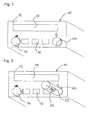
- the electronic built-in device 10 shown in FIG. 1 is, for example, a car radio with a front panel 12 into which various actuating elements 14, 16, a display 18 and a reading lamp 20 are integrated.
- the reading lamp 20 is cylindrical in the illustrated embodiment and can be sunk in a recess with a corresponding circular cross section in the front panel 12 of the electronic built-in device 10, as shown in Fig. 1.
- the actuator 14 is a rotary volume control with a circular cross-section.
- the cross section of the reading lamp 20 corresponds to the cross section of the volume control 14.
- both the reading lamp 20 in the state shown in FIG. 1 and the volume control 14 project slightly beyond the front panel 12.
- the reading lamp 20 and the volume control 14 are also arranged symmetrically right and left in the front panel 12.
- the car radio 10 is shown in FIG. 1, wherein the reading lamp 20 now projects further than the volume control 14 via the front panel 12 of the radio 10 out into the vehicle interior.
- a user can press the lamp 20 in the state shown in Fig. 1 in the manner of a button in the front panel 14, whereby it dissolves from a catch and, for example, by the tension of a spring along a guide out of the front panel slides.
- the reading lamp 20 is pivoted in Fig. 2 by about 70 ° about a perpendicular to the front panel 12 through the center of the reading lamp 20 extending axis.
- two LEDs 24 are integrated into the cylindrical body of the reading lamp 20 and covered by a rectangular, transparent window 22.
- the bulbs show down.
- the reading lamp 20 pivoted about an axis perpendicular to the front panel 12 through the center of the reading lamp 20 extending axis, so that the light emitting diodes 24 generate an obliquely right below the built-in appliance 10 light field.
- the two light-emitting diodes 24 can have different colors so that the user can select the color of the illumination by switching on only one of the diodes.
- multi-color LEDs can be used, which also allows the illumination color to be selected. In this case, the selection of the color in both cases can be made via a menu of the electrical built-in device 10.
- the reading lamp 20 may be guided so that when it is extended from the sunk in the front panel 12 position, automatically in the position shown in Fig. 2 is pivoted. It is also possible to pivot them manually in any other position anyway.
- the reading lamp 20 When the reading lamp 20 is sunk in the front panel of the built-in device 10, it is automatically turned off by a switch, not shown. Conversely, the reading lamp 20 is automatically turned on when moving out of the recessed position in the front panel 12 position.
Landscapes
- Engineering & Computer Science (AREA)
- Mechanical Engineering (AREA)
- Fittings On The Vehicle Exterior For Carrying Loads, And Devices For Holding Or Mounting Articles (AREA)
- Bipolar Transistors (AREA)
- Control Of Motors That Do Not Use Commutators (AREA)
- Noodles (AREA)
- Automobile Manufacture Line, Endless Track Vehicle, Trailer (AREA)
- Lighting Device Outwards From Vehicle And Optical Signal (AREA)
Description
- Die vorliegende Erfindung betrifft ein elektronisches Einbaugerät für ein Kraftfahrzeug wie z.B. ein Autoradio, ein Navigationssystem oder ein Telematiksystem.
- Aus der
DE 16 55 085 A ist ein Drucktastenschalter für ein Kraftfahrzeug bekannt, dessen Betätigungsfläche in Ausschaltstellung in etwa mit der Oberfläche eines Instrumentenbrettes abschließt und in Einschaltstellung aus dem Instrumentenbrett herausragt. Der Drucktastenschalter ist mit einer Lampe versehen und besitzt ein Fenster, aus dem Licht der Lampe austreten kann. In der Ausschaltstellung des Drucktastenschalters liegt das Fenster abgedeckt hinter einer Frontfläche des Instrumentenbrettes. In der Einschaltstellung des Druckschalters kann Licht durch das Fenster in den Fahrgastraum austreten. Die Lampe kann als Leselampe verwendet werden. - Üblicherweise sind Leselampen für Fahrer und/oder Beifahrer in Kraftfahrzeugen im Fahrzeughimmel integriert. Bei dem Betrieb einer solchen Leselampe kann jedoch der Fahrer geblendet und/ oder sein Nachtsichtvermögen reduziert werden. Durch unerwünschte Reflexionen auf der Windschutzscheibe kann die Sicht zusätzlich beeinträchtigt werden.
- Es ist eine Aufgabe der vorliegenden Erfindung, eine Leselampe so in einem Fahrzeug unterzubringen, dass der Fahrer bei angeschalteter Leselampe möglichst wenig geblendet wird.
- Diese Aufgabe wird durch die Merkmale des Anspruchs 1 gelöst und insbesondere dadurch, dass eine Leselampe in ein elektronisches Einbaugerät mit einer Frontblende integriert ist, wobei die Leselampe ein im Wesentlichen nur seitlich und/oder unterhalb der Leselampe liegendes Lichtfeld erzeugt.
- Elektronische Einbaugeräte der oben genannten Art sind in Kraftfahrzeugen üblicherweise unterhalb der Windschutzscheibe angeordnet. Ein seitlich und/oder unterhalb der Leselampe liegendes Lichtfeld kann daher keine unerwünschten Reflexionen an der Windschutzscheibe erzeugen.
- Die Leselampe und das von ihr ausgehende Lichtfeld befinden sich zudem weit unterhalb des Sichtfeldes des Fahrers, so dass dieser nicht geblendet wird.
- Der Fahrer kann also die Leselampe während der Fahrt eingeschaltet lassen, ohne dass seine Sicht dadurch beeinträchtigt würde, und kann dann im Stau oder an einer Ampel wartend beispielsweise eine Landkarte betrachten, ohne Zeit mit dem Einschalten einer Leselampe zu verlieren. Insbesondere für einen Beifahrer ist das erfindungsgemäße elektronische Einbaugerät von Vorteil, da er eine Landkarte, einen Reiseführer oder Ähnliches während der Fahrt beleuchten und lesen kann, ohne dass die Sicht des Fahrers dadurch beeinträchtigt wird.
- Erfindungsgemäß ist die Leselampe zwischen zwei Positionen beweglich, wobei sie in einer Position in der Frontblende des Einbaugeräts zumindest überwiegend versenkt ist und in der anderen Position über die Frontblende hinausragt. Die Leselampe kann also, insbesondere wenn sie nicht in Betrieb ist, in der Frontblende des Einbaugeräts vollständig oder zumindest überwiegend versenkt sein, und somit optisch wie auch mechanisch in dem Einbaugerät verschwinden. In diesem Fall ist sie auch vor Stößen und sonstigen äußeren Einwirkungen geschützt und ein Fahrzeuginsasse kann das elektronische Einbaugerät bedienen, ohne dass die Leselampe ihm dabei im Weg ist. In der anderen Position der Leselampe, in der diese über die Frontblende des elektronischen Einbaugeräts hinausragt, kann ein seitlich und/oder nach unten gerichtetes Lichtfeld erzeugt werden, welches seinen Mittelpunkt in einer gewissen Entfernung von dem elektronischen Einbaugerät hat. Dadurch kann eine Landkarte oder ein Buch bequem in das von der Leselampe erzeugte Lichtfeld gehalten werden.
- Erfindungsgemäß ist eine Schaltvorrichtung vorgesehen, welche die Leselampe ausschaltet, wenn sie in der Frontblende versenkt wird, und sie einschaltet, wenn sie aus dieser in die Frontblende versenkten Position herausbewegt wird. Der Fahrer bzw. Beifahrer muss dann keinen Schalter betätigen, um die Leselampe aus- oder einzuschalten, dies geschieht bereits durch das Bewegen der Leselampe von einer Position in die andere. Falls der Fahrer selbst die Lampe betätigt, wird er auf diese Weise möglichst wenig abgelenkt. Es kann beispielsweise ein Mechanismus vorgesehen sein, der dafür sorgt, dass die Leselampe, wenn sie im in die Frontblende versenkten Zustand leicht in die Frontblende hineingedrückt wird, sich aus einer Verrastung löst, und sich dann mit Hilfe einer Feder in die Position bewegt, in der sie über die Frontblende hinausragt, wobei sie dann gleichzeitig eingeschaltet wird.
- Vorteilhafte Ausführungsformen der Erfindung sind in der Beschreibung, den Figuren sowie den Unteransprüchen beschrieben.
- Die Leselampe kann an dem elektronischen Einbaugerät verschwenkbar gelagert sein. Insbesondere ist es vorteilhaft, wenn die Leselampe in der Position, in der sie über die Frontblende des Einbaugeräts hinausragt, verschwenkbar gelagert ist. Dies ermöglicht es, die Leselampe entweder in Richtung des Fahrers oder in Richtung des Beifahrers zu verschwenken, so dass je nach Bedarf beide die Leselampe benutzen können.
- Nach einer weiteren vorteilhaften Ausführungsform der Erfindung ist eine mechanische Führung vorgesehen, welche die Leselampe beim Versenken in die Frontblende des Einbaugeräts in eine Ausgangsposition verschwenkt. In diesem Fall ist es also nicht nötig, dass der Fahrer bzw. Beifahrer die Leselampe zuerst wieder in ihrer Ausgangsposition verschwenkt und dann in die Frontblende versenkt, sondern das Verschwenken geschieht automatisch, so dass die Leselampe mit einem einzigen Handgriff in die Frontblende des Einbaugeräts zurück versenkt werden kann.
- Genauso kann auch eine mechanische Führung vorgesehen sein, welche die Leselampe beim Ausfahren aus der in die Frontblende versenkten Position automatisch verschwenkt. So kann die Leselampe beispielsweise automatisch in eine Position gebracht werden, welche dem Fahrer ein bequemes Betrachten einer Landkarte ermöglicht. Auf diese Weise spart der Fahrer Zeit und wird nicht unnötig vom Führen des Fahrzeugs abgelenkt. Falls eine andere Position der Leselampe erwünscht ist, z.B., weil der Beifahrer sie verwenden möchte, kann sie manuell in diese andere Position verschwenkt werden.
- Nach einer bevorzugten Ausführungsform der Erfindung liegt die Leselampe neben Bedienelementen des Einbaugeräts und weist die gleiche Form wie zumindest eines der Bedienelemente auf. Im zumindest überwiegend in die Frontblende versenkten Zustand integriert sich die Leselampe dann unauffällig in die Frontblende, so dass ein harmonisches Gesamtbild entsteht. Bei dem Bedienelement kann es sich beispielsweise um einen drehbaren zylindrischen Lautstärkeregler oder auch um einen Knopf mit rechteckiger Oberfläche handeln.
- Als Leuchtmittel können unter anderem Leuchtdioden, Glühlampen oder eine Elektro-Lumineszenz-Folie verwendet werden. Um das Nachtsehvermögen des Fahrers nicht zu beeinträchtigen, ist es besonders vorteilhaft, eine rote Beleuchtung zu wählen. Die Leselampe kann aber auch verschiedenfarbige Leuchtmittel, beispielsweise eine Multi-Color-LED, aufweisen, wobei die Beleuchtungsfarbe vom Benutzer je nach Bedarf und Geschmack ausgewählt werden kann.
- Nachfolgend wird die vorliegende Erfindung rein beispielhaft anhand einer vorteilhaften Ausführungsform und unter Bezugnahme auf die beigefügten Zeichnungen beschrieben.
- Im Einzelnen zeigen:
- Fig. 1:
- ein elektronisches Einbaugerät mit einer Leselampe, welche in der Frontblende versenkt ist, und
- Fig. 2:
- das elektronische Einbaugerät von Fig. 1, wobei die Leselampe über die Frontblende hinausragt.
- Bei dem in Fig. 1 dargestellten elektronischen Einbaugerät 10 handelt es sich beispielsweise um ein Autoradio mit einer Frontblende 12, in die verschiedene Betätigungselemente 14, 16, ein Display 18 und eine Leselampe 20 integriert sind. Die Leselampe 20 ist im dargestellten Ausführungsbeispiel zylindrisch und kann in einer Aussparung mit korrespondierendem rundem Querschnitt in der Frontblende 12 des elektronischen Einbaugeräts 10 versenkt werden, wie in Fig. 1 dargestellt. Das Betätigungselement 14 ist ein drehbarer Lautstärkeregler mit kreisförmigem Querschnitt. Der Querschnitt der Leselampe 20 entspricht dem Querschnitt des Lautstärkereglers 14. Zudem stehen sowohl die Leselampe 20 in dem in Fig. 1 dargestellten Zustand als auch der Lautstärkeregler 14 etwas über die Frontblende 12 vor. Die Leselampe 20 und der Lautstärkeregler 14 sind außerdem symmetrisch rechts und links in der Frontblende 12 angeordnet.
- In Fig. 2 ist das Autoradio 10 aus Fig. 1 gezeigt, wobei die Leselampe 20 nun weiter als der Lautstärkeregler 14 über die Frontblende 12 des Radios 10 hinaus ins Fahrzeuginnere ragt. Um diesen Zustand herbeizuführen, kann ein Benutzer die Lampe 20 in dem in Fig. 1 gezeigten Zustand nach Art eines Tasters in die Frontblende 14 drücken, wodurch diese sich aus einer Verrastung löst und beispielsweise durch die Spannung einer Feder entlang einer Führung aus der Frontblende heraus gleitet. Im Vergleich zu der in Fig. 1 dargestellten Position ist die Leselampe 20 in Fig. 2 um etwa 70° um eine senkrecht zur Frontblende 12 durch die Mitte der Leselampe 20 verlaufende Achse verschwenkt.
- Als Leuchtmittel sind zwei Leuchtdioden 24 in den zylindrischen Korpus der Leselampe 20 integriert und von einem rechteckigen, durchsichtigen Fenster 22 verdeckt. In der in Fig. 1 dargestellten Grundposition der Leselampe 20 zeigen die Leuchtmittel nach unten. In der in Fig. 2 dargestellten Position ist die Leselampe 20, wie bereits oben erläutert, um eine senkrecht zur Frontblende 12 durch die Mitte der Leselampe 20 verlaufende Achse verschwenkt, so dass die Leuchtdioden 24 ein schräg rechts unterhalb des Einbaugeräts 10 liegendes Lichtfeld erzeugen.
- Die beiden Leuchtdioden 24 können verschieden Farben besitzen so dass der Benutzer durch Einschalten nur einer der Dioden die Farbe der Beleuchtung wählen kann. Alternativ können auch Multi-Color-Leuchtdioden verwendet werden, was ebenfalls ein Wählen der Beleuchtungsfarbe ermöglicht. Hierbei kann die Auswahl der Farbe in beiden Fällen über ein Menü des elektrischen Einbaugeräts 10 erfolgen.
- Die Leselampe 20 kann derart geführt sein, dass sie, wenn sie aus der in der Frontblende 12 versenkten Position ausgefahren wird, automatisch in die in Fig. 2 dargestellte Position verschwenkt wird. Auch ist es möglich, sie trotzdem manuell in eine beliebige andere Position zu verschwenken.
- Wenn die Leselampe 20 in die Frontblende des Einbaugeräts 10 versenkt wird, wird sie durch einen nicht dargestellten Schalter automatisch ausgeschaltet. Umgekehrt wird die Leselampe 20 beim Herausbewegen aus der in die Frontblende 12 versenkten Position automatisch eingeschaltet.
-
- 10
- elektronisches Einbaugerät
- 12
- Frontblende
- 14
- Betätigungselement
- 16
- Betätigungselement
- 18
- Display
- 20
- Leselampe
- 22
- Fenster
- 24
- Leuchtdiode
Claims (8)
- Elektronisches Einbaugerät (10) für ein Kraftfahrzeug mit einer Frontblende (12), in die eine Leselampe (20) integriert ist, welche ein im Wesentlichen nur seitlich und/oder unterhalb der Leselampe (20) liegendes Lichtfeld erzeugt und zwischen zwei Positionen beweglich ist, wobei sie in einer Position zumindest überwiegend in der Frontblende (12) des Einbaugeräts (10) versenkt ist und in der anderen Position über die Frontblende (12) hinaus ragt, wobei eine Schaltvorrichtung vorgesehen ist, welche die Leselampe (20) ausschaltet, wenn sie in der Frontblende (12) versenkt wird, und sie einschaltet, wenn sie aus dieser in die Frontblende (12) versenkten Position herausbewegt wird.
- Elektronisches Einbaugerät (10) nach Anspruch 1,
dadurch gekennzeichnet,
dass eine mechanische Führung vorgesehen ist, welche die Leselampe (20) beim Versenken in die Frontblende (12) des Einbaugeräts (10) in eine Ausgangsposition verschwenkt. - Elektronisches Einbaugerät (10) nach Anspruch 2 oder 3,
dadurch gekennzeichnet,
dass eine mechanische Führung vorgesehen ist, welche die Leselampe (20) beim Ausfahren aus der in der Frontblende (12) versenkten Position automatisch verschwenkt. - Elektronisches Einbaugerät (10) nach einem der vorstehenden Ansprüche,
dadurch gekennzeichnet,
dass die Leselampe (20) verschwenkbar gelagert ist. - Elektronisches Einbaugerät (10) nach einem der vorstehenden Ansprüche,
dadurch gekennzeichnet,
dass die Leselampe (20) in der Position, in der sie über die Frontblende (12) des Einbaugeräts (10) hinausragt, verschwenkbar ist. - Elektronisches Einbaugerät (10) nach einem der vorhergehenden Ansprüche,
dadurch gekennzeichnet,
dass die Leselampe (20) Bedienelementen (14, 16) des Einbaugeräts (10) benachbart ist und die gleiche Form wie zumindest eines der Bedienelemente (14) aufweist. - Elektronisches Einbaugerät (10) nach einem der vorhergehenden Ansprüche,
dadurch gekennzeichnet,
dass die Leselampe (20) zumindest ein verschiedenfarbiges Leuchtmittel (24) aufweist und eine Beleuchtungsfarbe vom Benutzer auswählbar ist. - Kraftfahrzeug mit einem elektronischen Einbaugerät (10) nach zumindest einem der vorstehenden Ansprüche, wobei das Einbaugerät (10) im Querschnitt gesehen unterhalb einer Horizontalebene angeordnet ist, die durch die Mitte eines Lenkrads des Kraftfahrzeugs verläuft.
Priority Applications (3)
| Application Number | Priority Date | Filing Date | Title |
|---|---|---|---|
| AT04008790T ATE377254T1 (de) | 2004-04-13 | 2004-04-13 | Einbaugerät |
| EP04008790A EP1587117B1 (de) | 2004-04-13 | 2004-04-13 | Einbaugerät |
| DE502004005357T DE502004005357D1 (de) | 2004-04-13 | 2004-04-13 | Einbaugerät |
Applications Claiming Priority (1)
| Application Number | Priority Date | Filing Date | Title |
|---|---|---|---|
| EP04008790A EP1587117B1 (de) | 2004-04-13 | 2004-04-13 | Einbaugerät |
Publications (2)
| Publication Number | Publication Date |
|---|---|
| EP1587117A1 EP1587117A1 (de) | 2005-10-19 |
| EP1587117B1 true EP1587117B1 (de) | 2007-10-31 |
Family
ID=34924585
Family Applications (1)
| Application Number | Title | Priority Date | Filing Date |
|---|---|---|---|
| EP04008790A Expired - Lifetime EP1587117B1 (de) | 2004-04-13 | 2004-04-13 | Einbaugerät |
Country Status (3)
| Country | Link |
|---|---|
| EP (1) | EP1587117B1 (de) |
| AT (1) | ATE377254T1 (de) |
| DE (1) | DE502004005357D1 (de) |
Families Citing this family (3)
| Publication number | Priority date | Publication date | Assignee | Title |
|---|---|---|---|---|
| DE102006021612A1 (de) * | 2006-05-09 | 2007-11-15 | Siemens Ag | Fahrzeuginnenleuchte |
| KR102292549B1 (ko) * | 2020-04-13 | 2021-08-20 | 이하성 | 여닫이작동 효율성이 있는 차량 실내용 출몰형 독서등 |
| IT202200022737A1 (it) * | 2022-11-04 | 2024-05-04 | Ferrari Spa | Veicolo stradale provvisto di un comando manuale per l'attivazione delle luci di emergenza lampeggianti |
Family Cites Families (5)
| Publication number | Priority date | Publication date | Assignee | Title |
|---|---|---|---|---|
| DE1655085C3 (de) * | 1967-09-16 | 1974-01-10 | Swf-Spezialfabrik Fuer Autozubehoer Gustav Rau Gmbh, 7120 Bietigheim | Drucktastenschalter für Fahrzeuge |
| JPS5215032A (en) * | 1975-10-06 | 1977-02-04 | Toyota Motor Corp | Light device for car |
| US5264670A (en) * | 1992-04-17 | 1993-11-23 | Aeroquip Corporation | Switch and light assembly |
| DE9205969U1 (de) * | 1992-05-02 | 1992-09-17 | Blaupunkt-Werke Gmbh, 31139 Hildesheim | Tastenanordnung für einen Tippschalter |
| DE10147254A1 (de) * | 2001-09-26 | 2003-04-24 | Kastriot Merlaku | Leseleuchte für Fahrzeuge |
-
2004
- 2004-04-13 DE DE502004005357T patent/DE502004005357D1/de not_active Expired - Fee Related
- 2004-04-13 EP EP04008790A patent/EP1587117B1/de not_active Expired - Lifetime
- 2004-04-13 AT AT04008790T patent/ATE377254T1/de not_active IP Right Cessation
Also Published As
| Publication number | Publication date |
|---|---|
| DE502004005357D1 (de) | 2007-12-13 |
| ATE377254T1 (de) | 2007-11-15 |
| EP1587117A1 (de) | 2005-10-19 |
Similar Documents
| Publication | Publication Date | Title |
|---|---|---|
| DE102013018784B4 (de) | Fahrzeug mit Beleuchtungsvorrichtung mit einer längsförmigen Beleuchtungseinrichtung | |
| DE19741377B4 (de) | Fahrzeug-Scheinwerfer mit einer bewegbaren Lichtquelle | |
| DE102011083915A1 (de) | Multifunktionsschalter für ein Fahrzeug mit einem Lichtmodul | |
| DE102008007930A1 (de) | Lichtschalter für Kraftfahrzeuge | |
| DE102009011710A1 (de) | Anordnung zur Luftverteilung im Innenraum eines Kraftfahrzeuges | |
| DE102005014816A1 (de) | Hochgesetzte Beleuchtungseinrichtung für Fahrzeuge, insbesondere Kraftfahrzeuge | |
| WO2017144042A1 (de) | Kraftfahrzeugschloss | |
| DE2357496A1 (de) | Einstellvorrichtung fuer kraftfahrzeuge | |
| DE19529533C2 (de) | Betätigungseinheit zum Betätigen von Einrichtungen eines Kraftfahrzeugs | |
| DE3737087A1 (de) | Elektrische schalter-kombination | |
| EP1959189A1 (de) | Scheinwerferanordnung, Verfahren zum Betreiben einer Scheinwerferanordnung und Kraftfahrzeug | |
| EP1587117B1 (de) | Einbaugerät | |
| DE3436391A1 (de) | Verfahren zur betaetigung der frontseitigen beleuchtungsanlage eines kraftfahrzeuges und schaltungsanordnung zur durchfuehrung des verfahrens | |
| DE102005001122A1 (de) | Anzeigesystem für Fahrzeuge | |
| EP1101654A2 (de) | Beleuchtungsvorrichtung für Gerätegruppen in Kraftfahrzeugen | |
| DE3545495A1 (de) | Frontseitige beleuchtungsanlage eines kraftfahrzeugs | |
| EP1074429A2 (de) | Lichtschaltereinheit | |
| DE10042442A1 (de) | Elektrisches Schaltgerät zur Betätigung unterschiedlicher elektrischer Funktionen in einem Kraftfahrzeug | |
| EP0818352B1 (de) | Lenkstockschalter für ein Kraftfahrzeug | |
| DE19530633A1 (de) | Optische Warnsignalanlage für Sonderfahrzeuge, insbesondere Fahrzeuge der Polizei, der Nothilfe, der Feuerwehr o. dgl. | |
| DE3730284A1 (de) | Innenleuchteneinheit fuer kraftfahrzeuge | |
| DE29818264U1 (de) | Beleuchtungsanlage für ein Kraftfahrzeug sowie Glühlampe für einen Richtungsanzeiger einer derartigen Beleuchtungsanlage | |
| DE202013102002U1 (de) | Beleuchteter Haltegriff mit Beleuchtungsmodi | |
| DE102005058502A1 (de) | Funktionseinheit für Kraftfahrzeuge | |
| DE10249817A1 (de) | Schaltanordnung zur Betätigung von Beleuchtungssystemen an einem Kraftfahrzeug |
Legal Events
| Date | Code | Title | Description |
|---|---|---|---|
| PUAI | Public reference made under article 153(3) epc to a published international application that has entered the european phase |
Free format text: ORIGINAL CODE: 0009012 |
|
| AK | Designated contracting states |
Kind code of ref document: A1 Designated state(s): AT BE BG CH CY CZ DE DK EE ES FI FR GB GR HU IE IT LI LU MC NL PL PT RO SE SI SK TR |
|
| AX | Request for extension of the european patent |
Extension state: AL HR LT LV MK |
|
| 17P | Request for examination filed |
Effective date: 20051117 |
|
| AKX | Designation fees paid |
Designated state(s): AT BE BG CH CY CZ DE DK EE ES FI FR GB GR HU IE IT LI LU MC NL PL PT RO SE SI SK TR |
|
| GRAP | Despatch of communication of intention to grant a patent |
Free format text: ORIGINAL CODE: EPIDOSNIGR1 |
|
| GRAS | Grant fee paid |
Free format text: ORIGINAL CODE: EPIDOSNIGR3 |
|
| GRAA | (expected) grant |
Free format text: ORIGINAL CODE: 0009210 |
|
| AK | Designated contracting states |
Kind code of ref document: B1 Designated state(s): AT BE BG CH CY CZ DE DK EE ES FI FR GB GR HU IE IT LI LU MC NL PL PT RO SE SI SK TR |
|
| REG | Reference to a national code |
Ref country code: GB Ref legal event code: FG4D Free format text: NOT ENGLISH |
|
| REG | Reference to a national code |
Ref country code: IE Ref legal event code: FG4D Free format text: LANGUAGE OF EP DOCUMENT: GERMAN |
|
| REG | Reference to a national code |
Ref country code: CH Ref legal event code: EP |
|
| REF | Corresponds to: |
Ref document number: 502004005357 Country of ref document: DE Date of ref document: 20071213 Kind code of ref document: P |
|
| ET | Fr: translation filed | ||
| NLV1 | Nl: lapsed or annulled due to failure to fulfill the requirements of art. 29p and 29m of the patents act | ||
| PG25 | Lapsed in a contracting state [announced via postgrant information from national office to epo] |
Ref country code: NL Free format text: LAPSE BECAUSE OF FAILURE TO SUBMIT A TRANSLATION OF THE DESCRIPTION OR TO PAY THE FEE WITHIN THE PRESCRIBED TIME-LIMIT Effective date: 20071031 Ref country code: ES Free format text: LAPSE BECAUSE OF FAILURE TO SUBMIT A TRANSLATION OF THE DESCRIPTION OR TO PAY THE FEE WITHIN THE PRESCRIBED TIME-LIMIT Effective date: 20080211 Ref country code: SE Free format text: LAPSE BECAUSE OF FAILURE TO SUBMIT A TRANSLATION OF THE DESCRIPTION OR TO PAY THE FEE WITHIN THE PRESCRIBED TIME-LIMIT Effective date: 20080131 |
|
| GBV | Gb: ep patent (uk) treated as always having been void in accordance with gb section 77(7)/1977 [no translation filed] | ||
| PG25 | Lapsed in a contracting state [announced via postgrant information from national office to epo] |
Ref country code: PL Free format text: LAPSE BECAUSE OF FAILURE TO SUBMIT A TRANSLATION OF THE DESCRIPTION OR TO PAY THE FEE WITHIN THE PRESCRIBED TIME-LIMIT Effective date: 20071031 Ref country code: PT Free format text: LAPSE BECAUSE OF FAILURE TO SUBMIT A TRANSLATION OF THE DESCRIPTION OR TO PAY THE FEE WITHIN THE PRESCRIBED TIME-LIMIT Effective date: 20080331 Ref country code: SI Free format text: LAPSE BECAUSE OF FAILURE TO SUBMIT A TRANSLATION OF THE DESCRIPTION OR TO PAY THE FEE WITHIN THE PRESCRIBED TIME-LIMIT Effective date: 20071031 Ref country code: BG Free format text: LAPSE BECAUSE OF FAILURE TO SUBMIT A TRANSLATION OF THE DESCRIPTION OR TO PAY THE FEE WITHIN THE PRESCRIBED TIME-LIMIT Effective date: 20080131 |
|
| REG | Reference to a national code |
Ref country code: IE Ref legal event code: FD4D |
|
| PG25 | Lapsed in a contracting state [announced via postgrant information from national office to epo] |
Ref country code: CZ Free format text: LAPSE BECAUSE OF FAILURE TO SUBMIT A TRANSLATION OF THE DESCRIPTION OR TO PAY THE FEE WITHIN THE PRESCRIBED TIME-LIMIT Effective date: 20071031 Ref country code: DK Free format text: LAPSE BECAUSE OF FAILURE TO SUBMIT A TRANSLATION OF THE DESCRIPTION OR TO PAY THE FEE WITHIN THE PRESCRIBED TIME-LIMIT Effective date: 20071031 |
|
| PG25 | Lapsed in a contracting state [announced via postgrant information from national office to epo] |
Ref country code: SK Free format text: LAPSE BECAUSE OF FAILURE TO SUBMIT A TRANSLATION OF THE DESCRIPTION OR TO PAY THE FEE WITHIN THE PRESCRIBED TIME-LIMIT Effective date: 20071031 Ref country code: RO Free format text: LAPSE BECAUSE OF FAILURE TO SUBMIT A TRANSLATION OF THE DESCRIPTION OR TO PAY THE FEE WITHIN THE PRESCRIBED TIME-LIMIT Effective date: 20071031 |
|
| PLBE | No opposition filed within time limit |
Free format text: ORIGINAL CODE: 0009261 |
|
| STAA | Information on the status of an ep patent application or granted ep patent |
Free format text: STATUS: NO OPPOSITION FILED WITHIN TIME LIMIT |
|
| 26N | No opposition filed |
Effective date: 20080801 |
|
| BERE | Be: lapsed |
Owner name: DELPHI TECHNOLOGIES, INC. Effective date: 20080430 |
|
| PG25 | Lapsed in a contracting state [announced via postgrant information from national office to epo] |
Ref country code: IE Free format text: LAPSE BECAUSE OF FAILURE TO SUBMIT A TRANSLATION OF THE DESCRIPTION OR TO PAY THE FEE WITHIN THE PRESCRIBED TIME-LIMIT Effective date: 20071031 |
|
| PG25 | Lapsed in a contracting state [announced via postgrant information from national office to epo] |
Ref country code: GB Free format text: LAPSE BECAUSE OF FAILURE TO SUBMIT A TRANSLATION OF THE DESCRIPTION OR TO PAY THE FEE WITHIN THE PRESCRIBED TIME-LIMIT Effective date: 20071031 Ref country code: MC Free format text: LAPSE BECAUSE OF NON-PAYMENT OF DUE FEES Effective date: 20080430 |
|
| REG | Reference to a national code |
Ref country code: CH Ref legal event code: PL |
|
| PG25 | Lapsed in a contracting state [announced via postgrant information from national office to epo] |
Ref country code: GR Free format text: LAPSE BECAUSE OF FAILURE TO SUBMIT A TRANSLATION OF THE DESCRIPTION OR TO PAY THE FEE WITHIN THE PRESCRIBED TIME-LIMIT Effective date: 20080201 Ref country code: LI Free format text: LAPSE BECAUSE OF NON-PAYMENT OF DUE FEES Effective date: 20080430 Ref country code: CH Free format text: LAPSE BECAUSE OF NON-PAYMENT OF DUE FEES Effective date: 20080430 Ref country code: EE Free format text: LAPSE BECAUSE OF FAILURE TO SUBMIT A TRANSLATION OF THE DESCRIPTION OR TO PAY THE FEE WITHIN THE PRESCRIBED TIME-LIMIT Effective date: 20071031 |
|
| PG25 | Lapsed in a contracting state [announced via postgrant information from national office to epo] |
Ref country code: FI Free format text: LAPSE BECAUSE OF FAILURE TO SUBMIT A TRANSLATION OF THE DESCRIPTION OR TO PAY THE FEE WITHIN THE PRESCRIBED TIME-LIMIT Effective date: 20071031 |
|
| PG25 | Lapsed in a contracting state [announced via postgrant information from national office to epo] |
Ref country code: BE Free format text: LAPSE BECAUSE OF NON-PAYMENT OF DUE FEES Effective date: 20080430 |
|
| PG25 | Lapsed in a contracting state [announced via postgrant information from national office to epo] |
Ref country code: CY Free format text: LAPSE BECAUSE OF FAILURE TO SUBMIT A TRANSLATION OF THE DESCRIPTION OR TO PAY THE FEE WITHIN THE PRESCRIBED TIME-LIMIT Effective date: 20071031 |
|
| PG25 | Lapsed in a contracting state [announced via postgrant information from national office to epo] |
Ref country code: AT Free format text: LAPSE BECAUSE OF NON-PAYMENT OF DUE FEES Effective date: 20080413 |
|
| PGFP | Annual fee paid to national office [announced via postgrant information from national office to epo] |
Ref country code: DE Payment date: 20090409 Year of fee payment: 6 Ref country code: FR Payment date: 20090417 Year of fee payment: 6 |
|
| PG25 | Lapsed in a contracting state [announced via postgrant information from national office to epo] |
Ref country code: HU Free format text: LAPSE BECAUSE OF FAILURE TO SUBMIT A TRANSLATION OF THE DESCRIPTION OR TO PAY THE FEE WITHIN THE PRESCRIBED TIME-LIMIT Effective date: 20080501 Ref country code: LU Free format text: LAPSE BECAUSE OF NON-PAYMENT OF DUE FEES Effective date: 20080413 |
|
| PG25 | Lapsed in a contracting state [announced via postgrant information from national office to epo] |
Ref country code: TR Free format text: LAPSE BECAUSE OF FAILURE TO SUBMIT A TRANSLATION OF THE DESCRIPTION OR TO PAY THE FEE WITHIN THE PRESCRIBED TIME-LIMIT Effective date: 20071031 |
|
| REG | Reference to a national code |
Ref country code: FR Ref legal event code: ST Effective date: 20101230 |
|
| PG25 | Lapsed in a contracting state [announced via postgrant information from national office to epo] |
Ref country code: FR Free format text: LAPSE BECAUSE OF NON-PAYMENT OF DUE FEES Effective date: 20100430 |
|
| PG25 | Lapsed in a contracting state [announced via postgrant information from national office to epo] |
Ref country code: IT Free format text: LAPSE BECAUSE OF NON-PAYMENT OF DUE FEES Effective date: 20080430 Ref country code: DE Free format text: LAPSE BECAUSE OF NON-PAYMENT OF DUE FEES Effective date: 20101103 |