EP1586914A2 - Digitale Filter für NMR- und MRI-Anwendungen - Google Patents
Digitale Filter für NMR- und MRI-Anwendungen Download PDFInfo
- Publication number
- EP1586914A2 EP1586914A2 EP05007504A EP05007504A EP1586914A2 EP 1586914 A2 EP1586914 A2 EP 1586914A2 EP 05007504 A EP05007504 A EP 05007504A EP 05007504 A EP05007504 A EP 05007504A EP 1586914 A2 EP1586914 A2 EP 1586914A2
- Authority
- EP
- European Patent Office
- Prior art keywords
- signal
- nmr
- signal component
- copies
- transient
- Prior art date
- Legal status (The legal status is an assumption and is not a legal conclusion. Google has not performed a legal analysis and makes no representation as to the accuracy of the status listed.)
- Granted
Links
Images



Classifications
-
- G—PHYSICS
- G01—MEASURING; TESTING
- G01R—MEASURING ELECTRIC VARIABLES; MEASURING MAGNETIC VARIABLES
- G01R33/00—Arrangements or instruments for measuring magnetic variables
- G01R33/20—Arrangements or instruments for measuring magnetic variables involving magnetic resonance
- G01R33/44—Arrangements or instruments for measuring magnetic variables involving magnetic resonance using nuclear magnetic resonance [NMR]
- G01R33/46—NMR spectroscopy
- G01R33/4625—Processing of acquired signals, e.g. elimination of phase errors, baseline fitting, chemometric analysis
Definitions
- Digital filters have become more modern in the receiving system for some time now NMR and MRI spectrometers used. They are usually called low-pass filters be designed simultaneously with the oversampling and the Decimation method applied and because the receiving system normally contains a quadrature detector, each receiving system two digital Filter needed.
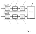
- FIG. 6 shows the last functional blocks of a modern NMR receiving system shown. You can see the two quadrature channels A and B with the two digital filters 3a and 3b and the two digitizers 2a and 2b, with which the both analog NMR signals of channels A and B are digitized.
- the sampling rate of the digitizers is usually chosen as high as possible in order to give more freedom to the design of the analogue anti-aliasing filters and, on the other hand, to profit from the resolution gain of the oversampling method .
- the digital filter makes it possible to limit the frequency bandwidth of the filtered NMR signal, and thus also to reduce the maximum frequency that can occur in the filtered NMR signal, much more data arrives than the Nyquist theorem requires. For this reason, a decimation of the data rate is also carried out after the digital filter (decimation method).
- analog low-pass filters In front of the two digitizers are analog low-pass filters, so-called anti-aliasing filters whose cut-off frequency must be lower than half the oversampling rate, so that the Nyquist criterion is not violated.
- the output signals of the two digital filters are fed to a computer, where they are subjected to a computing operation RV and transformed by means of a subsequent Fourier transformation to the desired NMR spectrum or MRI image.
- IIR Infinite Impulse Response
- FIR Finite Impulse Response
- the NMR signal F ' is shown at the output of the FIR filter. It is composed of the transient region B 1 of length T B , the actual NMR signal [F] 'of length T A , as well as the decay process B 2 of length T B. However, the entry and exit processes do not only consist of the shares B 1 resp. B 2 together, but also still have the shares [B 1 ] resp. [B 2 ], both within [F] '. Note also that the detection time T ERF of the NMR signal after the FIR filter is greater than that before the FIR filter, namely (T B + T A + T B ) versus T A.
- the group delay T B of the digital filter it is expedient to select the group delay T B of the digital filter so that an exact separation of the three signal ranges B 1 , [F] 'and B 2 is possible. This is achieved by selecting the group delay T B equal to an integer multiple of the period of the decimated sampling rate . Although this condition is not absolutely necessary, it leads to a much simplified signal processing.
- the task RV has the task of matching the detection time (T B + T A + T B ) of the filtered NMR signal F 'to the detection time T A of the NMR signal F at the input of the filter, ie to reduce it to T A , if possible without creating additional distortions in the frequency spectrum. In this way, the condition that the NMR spectra of the filtered and the unfiltered NMR signal correspond to each other as closely as possible to the filter function, can be met.
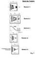
- the computing operation RV which is normally used today in high-resolution NMR spectroscopy, consists in the first step of filtering the filtered NMR signal with a window function W1 (t) provided specifically for this arithmetic operation (see FIG. 7, area 3). is multiplied, so that a NMR signal of length T A is left (see Figure 7, area 4). This is accomplished by choosing W1 (t) to multiply a range of 2xT B at zero at the end of the NMR signal and therefore allow it to be cut away. In this way, an NMR signal of length T A remains as desired.
- the steep phase response resulting from the digital filter is compensated by means of a large linear phase correction. This can firstly be achieved by a corresponding phase correction in the frequency domain, or secondly by cyclic rotation of the NMR signal in the time domain. In the second case, the transient B 1 "shifts to the end of F" (see Figure 7, area 5).
- the digital NMR signal F 'at the output of the digital filter contains usually unwanted spurious components that depend on the quality of the used receiving electronics.
- a disturbing DC component Be sure to be present before the application Window function W1 (t) and the Fourier transform must be eliminated because otherwise additional interfering components in the NMR spectrum can arise.
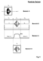
- FIG. 8 show an NMR signal with an exaggerated DC component S DC .
- Area 1 shows the DC component before filtering and area 2 after filtering, but both times without the settling and decaying processes.
- Area 3 shows only the DC component, but this time with the on and off swinging processes.
- a DC component is formed which consists of a step function of the height S DC delayed by T B , with rising and falling processes at the jump point (see FIG Fig.8, area 4).
- the value S DC can easily be determined from the function F 'by selecting the end region of the function F' and determining the value S DC from this by means of a mean value formation. Now that S DC is known, the pure jump function can be unambiguously defined without in-and-out processes. However, it is not enough to use this function to compensate for the DC component of F 'because the' on and off 'processes of F' would still be left over and cause disturbances in the NMR spectrum.
- the group delay T B can be approximately equal to or greater than T A , so that the computing process RV described for high-resolution NMR spectroscopy would completely fail here.
- area 1 since in the MRI normally with echo signals (see Figure 9, area 1) is worked, and these sound with a small value, reach a maximum value, then fall off again and ultimately reach a small value, is still a simple solution possible.
- the echo signal is shown at the output of the digital filter, and it is easy to see that T B > T A.
- the settling and decay processes B 1 and B 2 are normally negligibly small and can therefore be set equal to zero and cut away with the aid of the window function W1 (t) (see FIG. 9, area 3). In this case too, an echo signal of length T A is obtained as desired (see FIG. 9, area 4).
- the echo signal may also have a DC component, but as in high-resolution NMR spectroscopy.
- the aim of the method according to the invention is to define a new arithmetic operation RV which mathematically precisely compensates the influence of the group delay of digital, linear-phase filters.
- RV a new arithmetic operation
- the central idea in the derivation of the new computation RV is to that the implicit property of the Fourier transform, namely that they automatically a periodization of the NMR signal to be transformed is taken into account, consistently and mathematically accurately.
- the infinite chain of signal parts F which we want to call F1 is passed through the digital filter, and since a digital filter is a linear time-invariant system (LTI system), the superposition principle may be used , that is, the individual signal components F of F1 may be separated and individually passed through the digital filter and there added as a single filtered signal components F 'to each other again.
- the individual signal components of F2 should be denoted by F "Note that the Fourier transformation of F" must necessarily be identical to the Fourier transformation of F except for the influence of the filter function. This means, however, that the NMR spectrum of the two functions F and F "must also be identical except for the filter function, and this corresponds exactly to the desired target.
- the above process can also be described as follows.
- the filtered NMR signal F ' is imaginary copied in infinite number and the individual copies at intervals of T A before and after the signal F' positioned. This inevitably creates overlaps because the signal F 'and its copies are longer than T A as a result of their input and decay processes. If these copies are then added to the signal F ', the periodic signal F2 described above is formed, which is composed of all signal components F ".
- the signal F " may additionally with a window function W2 (t) are multiplied, which can be useful if the original one NMR signal F at the end of the NMR signal as already described, an abrupt Waste, which is inevitably also transferred to F. Such wastes generally generate distortions of the NMR lines, and these as much as possible To keep it small, F "is first multiplied by a window function written in the End region has a monotonous drop to zero, and only then the Fourier transform fed.
- FIG. 1 shows how first only the NMR signal [F] 'is selected and stored as value A (range 2). Subsequently, the decay B 2 of C ' -1 and the transient B 1 of C' +1 are selected and stored as value B (area 3). At the end, A and B are added, resulting in the desired signal F "of length T A (area 4).
- T A ⁇ T B more than three consecutive signals F 'must be taken into account.
- the minimum number of consecutive signals F 'which must be taken into account must be equal to 1 + 2 ⁇ N, where N is initially determined by the quotient value (T B / T A ), but subsequently to the the next higher integer must be rounded up.
- the DC component normally present in the calculated NMR signal F “must first be compensated before further computational manipulations on F" are carried out.
- the DC component consists only of a constant value S DC with no in-or out-of-cycles, and it is therefore sufficient to determine this by means of an averaging of the end region of F "and subtract it from the signal F".
- this compensation thus requires no knowledge of the filter parameters, and therefore the manufacturer of NMR spectrometer is not forced to pass these filter parameters to third party application software.
- the filtered NMR signal with the DC component S DC is shown in FIG. 2.
- region 3 the entire profile of the DC component of DC is shown in FIG It still has in-and-out processes, but after the two copies of the DC component have been positioned to the left and right of the original DC component (see Section 4) and all three DC components have been added together, this results in a DC component without in-and out-of-the-way oscillations (see section 5)
- the settling and deceleration processes have compensated each other, showing that the DC component of the signal F "only consists of a constant value S DC .
- N T B / T A , which is then rounded up to the next higher whole number.
Landscapes
- Physics & Mathematics (AREA)
- Engineering & Computer Science (AREA)
- Signal Processing (AREA)
- Spectroscopy & Molecular Physics (AREA)
- High Energy & Nuclear Physics (AREA)
- Condensed Matter Physics & Semiconductors (AREA)
- General Physics & Mathematics (AREA)
- Magnetic Resonance Imaging Apparatus (AREA)
Abstract
Description
- Am Ausgang des Filters entstehen mehr Datenpunkte als am Eingang eingegeben wurden. Durch geeignete Massnahmen kann jedoch dieses Merkmal kompensiert werden.
- Bei einer allfälligen Anwendung von Fensterfunktionen (Window Functions) und/oder von "Backward Linear Prediction" Methoden (BLP) muss der Einfluss der Gruppenlaufzeit berücksichtigt werden.
- Bei der Kompensation eines möglicherweise vorhandenen DC-Anteils im gefilterten NMR-Signal muss ebenfalls der Einfluss der Gruppenlaufzeit berücksichtigt werden.
- Fig.1
- Erfindungsgemässer Rechenvorgang RV, dargestellt für den Fall, dass die Gruppenlaufzeit TB kleiner oder gleich der Aquisitionszeit TA ist. Zu diesem Fall gehört z.B. die hochauflösende NMR-Spektroskopie. Das resultierende Signal F" enthält die beiden Ein- und Ausschwingvorgänge B1 resp. B2.
- Fig.2
- Bestimmung des DC-Anteils de Signals F" gemäss dem erfindungsgemässen Verfahren. Der resultierende DC-Anteil besteht nur aus einem konstanten Wert SDC. ohne irgendwelche Ein- oder Ausschwingvorgänge.
- Fig.3
- Erfindungsgemässer Rechenvorgang RV, dargestellt für den Fall, dass die Gruppenlaufzeit TB grösser als die Aquisitionszeit TA ist. Zu diesem Fall gehört z.B. die MRI. Das resultierende Signal F" enthält eine Mehrzahl von überlagerten Ein- und Ausschwingvorgängen B1 resp. B2.
- Fig.4
- Erfindungsgemässer Rechenvorgang RV für den allgemeinen Fall. Das resultierende Signal F" enthält eine Mehrzahl von überlagerten Ein- und Ausschwingvorgängen B1 resp. B2.
- Fig.5
- Detaillierte Darstellung des gefilterten NMR-Signals F' (siehe Bereich 2) sowie eine vereinfachte, symbolische Darstellung des gleichen NMR-Signals F' (siehe Bereich 3).
- Fig.6
- Aufbau des NF-Teils eines NMR- oder MRI-Empfangssystems. Dargestellt ist ein System, das typischerweise mit einer Quadratur Detektion arbeitet und deshalb zwei Kanäle A und B enthält.
- Fig.7
- Rechenvorgang RV für die hochauflösende NMR-Spektroskopie gemäss dem Stand der Technik. Die gewünschte Länge TA des resultierenden NMR-Signals konnte nur durch Wegschneiden von Signalanteilen und mit Hilfe einer Fensterfunktion W1(t) erreicht werden.
- Fig.8
- DC-Anteil der Funktion F" gemäss dem Stand der Technik. Dieser besteht aus einer Einheitssprungfunktion skaliert mit dem Wert SDC mit dem Einschwingvorgang am Sprungpunkt. Die Kompensation dieses DC-Anteils samt Einschwingvorgang benötigt Kenntnisse über die Filterparameter.
- Fig.9
- Rechenvorgang RV für die bildgebende MRI gemäss dem Stand der Technik. Die gewünschte Länge TA des resultierenden Echo-Signals wird durch Wegschneiden der Signalanteile B1 und B2 erreicht. Letztere sind im Allgemeinen zwar verschwindend klein, in gewissen Fällen jedoch können sie trotzdem zu einer nicht übersehbaren Verschlechterung der Qualität der MRI Bilderführen.
- MRI
- "Magnetic Resonance Imaging".
Bildgebendes NMR-Verfahren, bei dem geschaltete magnetische Gradientenfelder benutzt werden. - Passband
- Frequenzbereich, der vom digitalen Filter vollständig übertragen wird
- Transitionsband
- Bereich innerhalb des Frequenzganges des digitalen Filters, der den Übergang vom Pass- zum Stopband darstellt. Hier werden die Frequenzanteile weder vollständig unterdrückt, noch vollständig übertragen.
- Stopband
- Frequenzbereich, der vom digitalen Filter unterdrückt wird
- Anti-Aliasing-Filter
- Analoges Tiefpassfilter, das noch vor dem Digitizer liegt und für die Erfüllung des Nyquist-Kriteriums verantwortlich ist.
- Dezimation
- Reduktion der Samplingrate, die nach einer Begrenzung des Frequenzumfanges des NMR-Signals ausgeführt werden darf.
- Rechenvorgang
- RV Dient der rechnerischen Transformation des gefilterten NMR-Signals, so dass dieses die Länge TA erhält
- Kanal A
- Erster Kanal der Quadratur-Detektion
- Kanal B
- Zweiter Kanal der Quadratur-Detektion
- FID
- "Free Induction Decay". Typisches, in der Regel exponentiell abklingendes NMR-Signal, das z.B. nach einem 90° Anregungspuls entstehen kann.
- Echo
- Typisches, in der Regel exponentiell ansteigendes und anschliessend exponentiell abklingendes NMR-Signal, das z.B. nach einem 90° gefolgt von einem 180° Anregungspuls entstehen kann.
- DC-Anteil
- Unerwünschter Gleichstromanteil im NMR-Signal; in der Regel ein Restsignal der Elektronik, das sich dem FID- oder Echo-Signal überlagert (DC = Direct Current).
- SDC
- Betrag des DC-Anteils
- W1(t)
- Fensterfunktion, mit der das gefilterte NMR-Signal nach dem bisherigen Rechenverfahren RV modifiziert werden musste.
- W2(t)
- Fensterfunktion, mit der das NMR-Signal noch vor der Fourier-Transformation multipliziert wird, um die Qualität des NMR-Spektrums zu verbessern. (z.B. Reduktion des Truncation-Effektes)
- Truncation-Effekt
- Linienverzerrungen im NMR-Spektrum, die z.B. durch nicht abgeklungene NMR-Signale entstehen können.
- F
- NMR-Signal am Eingang des digitalen Filters
- F'
- NMR-Signal am Ausgang des digitalen Filters
- [F]'
- Anteil des NMR-Signals F' am Ausgang des digitalen Filters, der direkt in Bezug zum NMR-Signal F am Eingang des digitalen Filters steht.
- F"
- NMR-Signal nach erfolgtem Rechenvorgang RV und ohne explizite Kompensation des Phasenganges.
- F"'
- NMR-Signal nach erfolgtem Rechenvorgang RV und inkl. einer expliziten Kompensation des Phasenganges.
- Terf
- Erfassungszeit des gesamten NMR-Signals nach der digitalen Filterung
- TA
- Länge des NMR-Signals F (= Aquisitionszeit)
- TB
- Gruppenlaufzeit des digitalen Filters. Die Ein- und Ausschwingvorgänge B1 und B2 im gefilterten NMR-Signal besitzen beide diese Länge TB.
- B1
- Bereich vor der Funktion [F]', der einen Einschwingvorgang enthält.
- B2
- Bereich nach der Funktion [F]', der einen Ausschwingvorgang enthält
- [B1]
- Anfangsbereich innerhalb des Signals [F]', der einen Einschwingvorgang enthält
- [B2]
- Endbereich innerhalb des Signals [F]', der einen Ausschwingvorgang enthält
- N
- Anzahl der Kopien von F', die vor und nach dem Signal F' positioniert werden müssen, um daraus das Signal F" gemäss dem erfindungsgemässen Verfahren zu berechnen.
- 1a, 1b
- Analoge Tiefpass Filter, sogenannte Anti-Aliasing-Filter, die für die Einhaltung des Nyquist-Kriteriums verantwortlich sind.
- 2a, 2b
- Digitizer, mit denen die beiden analogen NMR-Signale, die in Quadratur zu einander stehen, digitalisiert werden.
- 3a, 3b
- Digitale Filter, um den Frequenzbereich des NMR-Signals einzuschränken und danach eine Dezimation einleiten zu können.
- 4
- Rechner, der den Rechenvorgang RV und die Fourier-Transformation ausführt.
Claims (5)
- Verfahren zum Betrieb eines Kernspinresonanz(=NMR)- oder eines bildgebenden Magnetresonanz(=MRI)-Spektrometers mit einem im Niederfrequenzbereich eines Empfangssystems eingebauten digitalen Filter, in dessen Eingang ein NMR-Signal der zeitlichen Länge TA eingespeist wird, und dessen Ausgangssignal aus einem Einschwingvorgang B1 der zeitlichen Länge TB, einem Signalanteil [F]' bestehend aus einem gefilterten FID- oder Echo-Signal der zeitlichen Länge TA sowie einem Ausschwingvorgang B2 der zeitlichen Länge TB besteht, wobei dieses Ausgangssignal zuerst mit Hilfe eines Rechenvorganges RV modifiziert und anschließend durch eine Fourier-Transformation zu einem gewünschten NMR-Spektrum transformiert wird,
dadurch gekennzeichnet, dass beim Rechenvorgang RV zuerst nur der Signalanteil [F]' erfasst wird, dass anschließend mindestens N Kopien des Einschwingvorganges B1 in positiven zeitlichen Abständen TA zueinander erzeugt und auf dem Signalanteil [F]' zeitlich so positioniert werden, dass das Ende des ersten Einschwingvorganges auf das Ende des Signalanteils [F]' zu liegen kommt, dass zudem mindestens N Kopien des Ausschwingvorganges B2 in negativen zeitlichen Abständen TA zueinander erzeugt und auf dem Signalanteil [F]' zeitlich so positioniert werden, dass der Anfang des ersten Ausschwingvorganges auf den Anfang des Signalanteils [F]' zu liegen kommt, und dass am Ende alle so definierten N Kopien des Einschwingvorganges B1 und N Kopien des Ausschwingvorganges B2 zum Signalanteil [F]' addiert werden, und davon nur der Bereich TA, der den Signalanteil [F]' enthält, als resultierendes Signal F" des Rechenvorganges RV gewählt wird, wobei die Zahl N mit Hilfe der Formel N = TB / TA zu berechnen und auf die nächst höhere ganze Zahl aufzurunden ist. - Verfahren nach Anspruch 1, dadurch gekennzeichnet, dass der DC-Anteil im resultierenden Signal F" durch eine simple Subtraktion eines konstanten Wertes SDC kompensiert wird und zum gewünschten DC-kompensierten Signal F" führt, wobei der Wert SDC durch eine Mittelwert-Bildung des Endbereichs des resultierenden Signals F" bestimmt wird.
- Verfahren nach Anspruch 2, dadurch gekennzeichnet, dass das DCkompensierte Signal F" mit einer Fensterfunktion W2(t) multipliziert wird, bevor sie anschließend der Fourier-Transformation zugeführt wird.
- Verfahren nach Anspruch 2, dadurch gekennzeichnet, dass am Ende des DC-kompensierten Signals F" ein Bereich aus lauter Nullwerten angehängt wird (=Zero Filling), und das so entstandene Signal anschließend der Fourier-Transformation zugeführt wird.
- Kernspinresonanz(=NMR)-Spektrometer oder bildgebendes Magnetresonanz(=MRI)-Spektrometer mit einem im Niederfrequenzbereich eines Empfangssystems eingebauten digitalen Filter, der nach dem Verfahren gemäß einem der vorhergehenden Ansprüche arbeitet.
Applications Claiming Priority (2)
| Application Number | Priority Date | Filing Date | Title |
|---|---|---|---|
| DE102004017667A DE102004017667B4 (de) | 2004-04-10 | 2004-04-10 | Digitale Filter für NMR- und MRI-Anwendungen |
| DE102004017667 | 2004-04-10 |
Publications (3)
| Publication Number | Publication Date |
|---|---|
| EP1586914A2 true EP1586914A2 (de) | 2005-10-19 |
| EP1586914A3 EP1586914A3 (de) | 2006-01-11 |
| EP1586914B1 EP1586914B1 (de) | 2010-03-03 |
Family
ID=34934799
Family Applications (1)
| Application Number | Title | Priority Date | Filing Date |
|---|---|---|---|
| EP05007504A Expired - Lifetime EP1586914B1 (de) | 2004-04-10 | 2005-04-06 | Digitale Filter für NMR- und MRI-Anwendungen |
Country Status (4)
| Country | Link |
|---|---|
| US (1) | US7071691B2 (de) |
| EP (1) | EP1586914B1 (de) |
| JP (1) | JP4157538B2 (de) |
| DE (2) | DE102004017667B4 (de) |
Families Citing this family (4)
| Publication number | Priority date | Publication date | Assignee | Title |
|---|---|---|---|---|
| DE102006001194B4 (de) * | 2006-01-10 | 2008-12-11 | Bruker Biospin Gmbh | Verfahren zur Ansteuerung eines Netzgeräts einer Magnetspule mittels automatischer digitaler Preemphasis für dynamische NMR-Magnetfelder durch digitale IIR-Filter |
| US8155466B2 (en) * | 2008-03-11 | 2012-04-10 | General Electric Company | Methods and apparatus for reducing noise in images |
| JP5355044B2 (ja) * | 2008-11-11 | 2013-11-27 | 株式会社東芝 | 磁気共鳴映像装置 |
| EP4502636B1 (de) * | 2023-08-04 | 2025-10-01 | Bruker Biospin GmbH & Co. KG | Systeme und verfahren zur schnellen quantitativen nmr-spektrumserfassung |
Family Cites Families (5)
| Publication number | Priority date | Publication date | Assignee | Title |
|---|---|---|---|---|
| US4992736A (en) * | 1989-08-04 | 1991-02-12 | General Electric Company | Radio frequency receiver for a NMR instrument |
| US5170123A (en) | 1989-08-11 | 1992-12-08 | Picker International, Inc. | Magnetic resonance imager with digital transmitter/receiver |
| US5560361A (en) * | 1994-01-31 | 1996-10-01 | General Electric Company | MRI system with time varying gradient during signal acquisition |
| US5652518A (en) * | 1996-06-11 | 1997-07-29 | Varian Associates, Inc. | Digital filter pre-charging |
| US6633162B2 (en) * | 2001-08-22 | 2003-10-14 | Ge Medical Systems Global Technology Company, Llc | System and method for filtering frequency encoded imaging signals |
-
2004
- 2004-04-10 DE DE102004017667A patent/DE102004017667B4/de not_active Expired - Fee Related
-
2005
- 2005-03-11 US US11/077,570 patent/US7071691B2/en not_active Expired - Lifetime
- 2005-04-06 EP EP05007504A patent/EP1586914B1/de not_active Expired - Lifetime
- 2005-04-06 DE DE502005009116T patent/DE502005009116D1/de not_active Expired - Lifetime
- 2005-04-08 JP JP2005112559A patent/JP4157538B2/ja not_active Expired - Lifetime
Also Published As
| Publication number | Publication date |
|---|---|
| EP1586914B1 (de) | 2010-03-03 |
| DE102004017667A1 (de) | 2005-11-17 |
| US7071691B2 (en) | 2006-07-04 |
| JP2005305153A (ja) | 2005-11-04 |
| DE102004017667B4 (de) | 2006-11-30 |
| DE502005009116D1 (de) | 2010-04-15 |
| US20050225324A1 (en) | 2005-10-13 |
| JP4157538B2 (ja) | 2008-10-01 |
| EP1586914A3 (de) | 2006-01-11 |
Similar Documents
| Publication | Publication Date | Title |
|---|---|---|
| DE2705386C3 (de) | Verfahren zum Gewinnen von von Rauschsignalen weitgehend freien Impulssignalen sowie Signalverarbeitungsvorrichtung zur Durchführung des Verfahrens | |
| DE10235062B4 (de) | Filterverfahren und A/D-Wandlergerät mit einer Filterfunktion | |
| DE3121972C2 (de) | ||
| DE69520524T2 (de) | Filter zur Entfernung von Vielwegverzerrungen | |
| DE3720382A1 (de) | Bandpass-filtervorrichtung fuer abgetastete signalwerte | |
| DE19802568A1 (de) | Hörhilfe mit Kompensation von akustischer und/oder mechanischer Rückkopplung | |
| DE69224625T2 (de) | Verfahren zum detektieren eines disable-tonsignals eines echokompensators | |
| DE3333984A1 (de) | Unterteiltes transversalfilter | |
| DE112011105183T5 (de) | Block und Verfahren zur gemeinsamen Kanalimpulsantwort/DC-Offset (CIR)/(DCO) -Bestimmung | |
| DE69118372T2 (de) | Dezimationsfilter für Sigma Delta Konverter und Datenendeinrichtung mit einem solchen Filter | |
| DE69321011T2 (de) | Verfahren und Gerät zur Rauschmessung | |
| DE10255687B4 (de) | Verfahren zur Verringerung des Crestfaktors eines Multiträgersignals | |
| EP0777326B1 (de) | Verfahren und Vorrichtung zur Filterung eines Audiosignals | |
| EP1586914B1 (de) | Digitale Filter für NMR- und MRI-Anwendungen | |
| EP1458216B1 (de) | Vorrichtung und Verfahren zur Adaption von Hörgerätemikrofonen | |
| DE102005018858B4 (de) | Digitales Filter und Verfahren zur Bestimmung seiner Koeffizienten | |
| DE69524331T2 (de) | Schaltung zur automatischen Verstärkungsregelung und Vorrichtung mit einer solchen Schaltung | |
| DE4020643A1 (de) | Verfahren zur tiefpassfilterung und anordnung zur durchfuehrung des verfahrens | |
| EP2667509B1 (de) | Digitales Filter | |
| DE102018129062B3 (de) | Filterverfahren und filter | |
| EP1290791A1 (de) | Digitales interpolationsfilter | |
| DE69015193T2 (de) | Schaltung zur audiosignalverarbeitung. | |
| DE10302234A1 (de) | Flexibler Dezimator | |
| EP1091214B1 (de) | Verfahren und Vorrichtung zur Aufbereitung von Messsignalen | |
| DE102019124285A1 (de) | Dekorrelation von eingangssignalen |
Legal Events
| Date | Code | Title | Description |
|---|---|---|---|
| PUAI | Public reference made under article 153(3) epc to a published international application that has entered the european phase |
Free format text: ORIGINAL CODE: 0009012 |
|
| AK | Designated contracting states |
Kind code of ref document: A2 Designated state(s): AT BE BG CH CY CZ DE DK EE ES FI FR GB GR HU IE IS IT LI LT LU MC NL PL PT RO SE SI SK TR |
|
| AX | Request for extension of the european patent |
Extension state: AL BA HR LV MK YU |
|
| PUAL | Search report despatched |
Free format text: ORIGINAL CODE: 0009013 |
|
| AK | Designated contracting states |
Kind code of ref document: A3 Designated state(s): AT BE BG CH CY CZ DE DK EE ES FI FR GB GR HU IE IS IT LI LT LU MC NL PL PT RO SE SI SK TR |
|
| AX | Request for extension of the european patent |
Extension state: AL BA HR LV MK YU |
|
| 17P | Request for examination filed |
Effective date: 20051215 |
|
| AKX | Designation fees paid |
Designated state(s): CH DE FR GB LI |
|
| GRAP | Despatch of communication of intention to grant a patent |
Free format text: ORIGINAL CODE: EPIDOSNIGR1 |
|
| GRAS | Grant fee paid |
Free format text: ORIGINAL CODE: EPIDOSNIGR3 |
|
| GRAA | (expected) grant |
Free format text: ORIGINAL CODE: 0009210 |
|
| AK | Designated contracting states |
Kind code of ref document: B1 Designated state(s): CH DE FR GB LI |
|
| REG | Reference to a national code |
Ref country code: GB Ref legal event code: FG4D Free format text: NOT ENGLISH |
|
| REG | Reference to a national code |
Ref country code: CH Ref legal event code: EP |
|
| REF | Corresponds to: |
Ref document number: 502005009116 Country of ref document: DE Date of ref document: 20100415 Kind code of ref document: P |
|
| PLBE | No opposition filed within time limit |
Free format text: ORIGINAL CODE: 0009261 |
|
| STAA | Information on the status of an ep patent application or granted ep patent |
Free format text: STATUS: NO OPPOSITION FILED WITHIN TIME LIMIT |
|
| 26N | No opposition filed |
Effective date: 20101206 |
|
| REG | Reference to a national code |
Ref country code: FR Ref legal event code: PLFP Year of fee payment: 12 |
|
| REG | Reference to a national code |
Ref country code: FR Ref legal event code: PLFP Year of fee payment: 13 |
|
| REG | Reference to a national code |
Ref country code: FR Ref legal event code: PLFP Year of fee payment: 14 |
|
| REG | Reference to a national code |
Ref country code: DE Ref legal event code: R082 Ref document number: 502005009116 Country of ref document: DE Representative=s name: KOHLER SCHMID MOEBUS PATENTANWAELTE PARTNERSCH, DE Ref country code: DE Ref legal event code: R081 Ref document number: 502005009116 Country of ref document: DE Owner name: BRUKER SWITZERLAND AG, CH Free format text: FORMER OWNER: BRUKER BIOSPIN AG, FAELLANDEN, CH |
|
| REG | Reference to a national code |
Ref country code: CH Ref legal event code: PFA Owner name: BRUKER SWITZERLAND AG, CH Free format text: FORMER OWNER: BRUKER BIOSPIN AG, CH |
|
| P01 | Opt-out of the competence of the unified patent court (upc) registered |
Effective date: 20231220 |
|
| PGFP | Annual fee paid to national office [announced via postgrant information from national office to epo] |
Ref country code: GB Payment date: 20240423 Year of fee payment: 20 |
|
| PGFP | Annual fee paid to national office [announced via postgrant information from national office to epo] |
Ref country code: DE Payment date: 20240418 Year of fee payment: 20 |
|
| PGFP | Annual fee paid to national office [announced via postgrant information from national office to epo] |
Ref country code: CH Payment date: 20240501 Year of fee payment: 20 |
|
| PGFP | Annual fee paid to national office [announced via postgrant information from national office to epo] |
Ref country code: FR Payment date: 20240419 Year of fee payment: 20 |
|
| REG | Reference to a national code |
Ref country code: DE Ref legal event code: R071 Ref document number: 502005009116 Country of ref document: DE |
|
| REG | Reference to a national code |
Ref country code: CH Ref legal event code: PL |
|
| REG | Reference to a national code |
Ref country code: GB Ref legal event code: PE20 Expiry date: 20250405 |
|
| PG25 | Lapsed in a contracting state [announced via postgrant information from national office to epo] |
Ref country code: GB Free format text: LAPSE BECAUSE OF EXPIRATION OF PROTECTION Effective date: 20250405 |