EP1586396B1 - Kompaktierpresse - Google Patents
Kompaktierpresse Download PDFInfo
- Publication number
- EP1586396B1 EP1586396B1 EP20050102126 EP05102126A EP1586396B1 EP 1586396 B1 EP1586396 B1 EP 1586396B1 EP 20050102126 EP20050102126 EP 20050102126 EP 05102126 A EP05102126 A EP 05102126A EP 1586396 B1 EP1586396 B1 EP 1586396B1
- Authority
- EP
- European Patent Office
- Prior art keywords
- cross
- press
- supporting table
- rim
- lamina
- Prior art date
- Legal status (The legal status is an assumption and is not a legal conclusion. Google has not performed a legal analysis and makes no representation as to the accuracy of the status listed.)
- Expired - Lifetime
Links
Images
Classifications
-
- B—PERFORMING OPERATIONS; TRANSPORTING
- B22—CASTING; POWDER METALLURGY
- B22F—WORKING METALLIC POWDER; MANUFACTURE OF ARTICLES FROM METALLIC POWDER; MAKING METALLIC POWDER; APPARATUS OR DEVICES SPECIALLY ADAPTED FOR METALLIC POWDER
- B22F3/00—Manufacture of workpieces or articles from metallic powder characterised by the manner of compacting or sintering; Apparatus specially adapted therefor ; Presses and furnaces
- B22F3/02—Compacting only
- B22F3/03—Press-moulding apparatus therefor
-
- B—PERFORMING OPERATIONS; TRANSPORTING
- B30—PRESSES
- B30B—PRESSES IN GENERAL
- B30B15/00—Details of, or accessories for, presses; Auxiliary measures in connection with pressing
- B30B15/02—Dies; Inserts therefor; Mounting thereof; Moulds
- B30B15/026—Mounting of dies, platens or press rams
-
- B—PERFORMING OPERATIONS; TRANSPORTING
- B30—PRESSES
- B30B—PRESSES IN GENERAL
- B30B15/00—Details of, or accessories for, presses; Auxiliary measures in connection with pressing
- B30B15/04—Frames; Guides
- B30B15/041—Guides
Definitions
- the present invention relates to a press for compacting metallic powders within a die of a particular shape, which is suitable to manufacture mechanical components.
- the machining processes for which the compaction of metallic powders is used are casting (pressure die-casting) and sintering.
- Casting requires the powders compacted inside the die to be brought to a temperature that is higher than their melting point for a time that is sufficient to ensure complete melting of the compacted mass.
- Sintering is the operation by means of which metallic (or ceramic) powders are agglomerated, at temperatures lower than the melting point, by virtue of diffusion phenomena. It is performed by heating the powders (usually precompressed when cold) in furnaces that are generally of the tunnel type. During sintering, extremely low shrinkage is observed and the density of the resulting parts is always lower than the density that can be obtained by casting; with respect to casting, sintering has the advantage, which is substantial especially in the case of high-melting materials, of working at lower temperatures and of obtaining parts that have their finished dimensions.
- presses have a certain number of guiding bars, on which a containment rim supporting cross-member is fitted so that it can slide. Below the containment rim there is a lower plug, which is aligned with the lower opening of said containment rim, and an upper plug is arranged in an upper region.
- Replacing the containment rim and the lower plug for example to change the size of the mechanical part being made, entails extracting from the machine the entire die supporting assembly with the adapter that comprises the cross-member, the containment rim and a corresponding footing.
- the aim of the present invention is to obviate the described drawbacks and to meet the mentioned requirements, by providing a compaction press in which the operations for removing and replacing the die supporting assembly (known as "adapter" in the jargon) are simplified and in which the alignment between the containment rim of the die and the upper plug is ensured at each assembly.
- a compaction press in which the operations for removing and replacing the die supporting assembly (known as "adapter” in the jargon) are simplified and in which the alignment between the containment rim of the die and the upper plug is ensured at each assembly.
- an object of the present invention is to provide a structure that is compact and does not require the provision of receptacles in the flooring or other foundation work.
- Another object of the present invention is to provide a press that has a simple structure, is relatively easy to provide in practice, safe in use, effective in operation, and has a relatively low cost.
- the present compacting press of the type that comprises one or more pairs of upper and lower plugs, a die supporting assembly, constituted by a cross-member that can perform a translational motion along appropriately provided guides fixed to the structure of the press, a die supporting containment rim and a footing, and the corresponding movement means, characterized in that guiding columns are distributed substantially along the external perimeter of the press and are fixed to the same structure, said columns guiding both said cross-member and an upper plate for accommodating the upper plug, and in that said cross-member has a frustum-shaped receptacle, whose shape and dimensions are complementary to those of the die supporting containment rim, the containment rim and the receptacle being mutually associable, in coaxiality conditions imposed by the taper, by virtue of removable coupling elements when they are forced one inside the other.
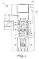
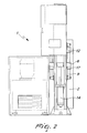
- the reference numeral 1 generally designates a compaction press.
- the press 1 comprises a supporting structure 2, which rests (and is optionally also fixed) on the floor; a movable arm 3 for supporting a management and control unit 4 is associated with the structure 2.
- the press 1 is provided with one or more pairs of plugs, an upper plug 5 and a lower plug 6, and a die supporting assembly 7 constituted by a cross-member 8, which can perform a translational motion along four guiding columns 9, which are fixed to the structure 1 and are distributed substantially along the external perimeter of the cross-member 8 proximate to the corners, by a containment rim supporting table 10, and by a footing 11.
- a plate 12 for accommodating the upper plug 5 is also guided along the columns 9.
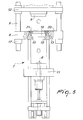
- the cross-member 8 is provided with a frustum-shaped receptacle 13, whose shape and dimensions are complementary to the containment rim supporting table 10, said containment rim supporting table and said receptacle being mutually associable, in coaxial conditions imposed by the taper, by bolting when they are forced one inside to the other.
- the frustum-shaped receptacle 13 and the containment rim supporting table 10 have an angle comprised between two diametrically opposite generatrices that span substantially 30°.
- the cross-member 8 can perform a vertical translational motion by means of two hydraulic pistons 14, which are arranged in diametrically opposite positions with respect to the receptacle 13 and have an upper movable end that is rigidly coupled to the lower face of the cross-member 8 and a lower end that is rigidly coupled to the supporting structure 2.
- the pistons 14 are actuated simultaneously and are mutually controlled, in terms of position and speed, for the correct translational motion of the cross-member 8: any advancement of one with respect to the other would in fact entail the tilting of the cross-member, with consequent malfunction of the press 1 and misalignment between the containment rim 18 and the plugs 5 and 6.
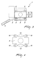
- the cross-member 8 is constituted by a metallic element, which has a substantially rectangular cross-section with four external arms 15, which protrude substantially from the corners along the directions of the diagonals, each arm 15 having an end hole 16 which accommodates, even indirectly, a respective column 9; each end hole can in fact accommodate stably a bush 17, which can slide on the respective column 9.
- the plate 12 is shaped like the cross-member 9 and has respective arms with end holes with which the bushes are associated, said bushes being able to slide on the respective columns 9.
- the containment rim 18 is mounted on the containment rim supporting table 10 so that the upper end protrudes slightly from the upper face of the containment rim supporting table 10.
- the cross-member 8 supports a fixed lamina 20, which is mounted on top, and a removable lamina 21, which is fixed above the upper end of the containment rim 18 and protrudes from the containment rim supporting table 10: the fixed lamina 20 and the movable lamina 21 have the same thickness.
- a cup 22 for feeding the powders to the die receives the powders from a hopper 23 through a duct 24; the cup 22 can slide on the upper surface of the laminas 20 and 21, and in the inactive position rests exclusively on the fixed lamina 20 and can move by way of the action of a motor 25 from said inactive position to the position for releasing the powders that corresponds to its overlap on the upper opening of the containment rim 18.
- the cup 22 has scrapers, which ensure that in sliding on the surface of the laminas 20 and 21 it does not scatter metallic powders thereon; gliding of the cup 22 on the laminas 20 and 21 is ensured by the fact that the laminas have the same thickness and therefore there are no discontinuities in the transition from one to the other.
- the die supporting assembly with the new containment rim 18 mounted thereon, can then be arranged again below the cross-member 8, making the cross-member 8 descend until the seat 13 is forced onto the rim supporting table 10, so that their taper forces their mutual alignment. At this point, it is possible to fix the containment rim supporting table 10 by bolting to the cross-member 8.
- the cross-member 8 and the plate 12 are constantly guided on the fixed columns 9 and are therefore perfectly aligned, and by ensuring, by way of the conical coupling, a perfect alignment between the receptacle 13 and the rim supporting table 10, the containment rim 18 is perfectly aligned with the upper plug 5 and with the lower plug 6. This ensures that the pressing operations are performed with maximum efficiency, obtaining correctly formed products and avoiding the risk of damaging the mating parts due to incorrect alignments.
- the cup for feeding the powders 22 to the containment rim 18 continues to rest on the fixed lamina 20 in the inactive position: advantageously with respect to conventional presses, it is not necessary to disassemble the cup 22 as well, an operation which requires interrupting the duct 24 to prevent the outflow of the powders.
Landscapes
- Engineering & Computer Science (AREA)
- Mechanical Engineering (AREA)
- Manufacturing & Machinery (AREA)
- Press Drives And Press Lines (AREA)
- Powder Metallurgy (AREA)
- Presses And Accessory Devices Thereof (AREA)
Claims (11)
- Verdichtungspresse der Art, die mindestens ein Paar von Stopfen, einen oberen (5) und einen unteren (6), eine Matrizenträgeranordnung (7), bestehend aus einer Traverse (8), die eine Verschiebebewegung entlang entsprechend bereitgestellter Führungen ausführen kann und die an der Struktur der Presse (1) befestigt ist, einen Einhausungsrandträgertisch (10) und eine Basis (11) sowie die entsprechenden Bewegungsmittel umfasst, dadurch gekennzeichnet, dass an der Struktur (1) befestigte Führungssäulen (9) im Wesentlichen entlang des äußeren Umfangs der Traverse (8) verteilt sind, wobei die Säulen (9) sowohl die Traverse (8) als auch eine obere Platte (12) zur Aufnahme des oberen Stopfens (5) führen, und dadurch, dass die Traverse (8) eine kegelstumpfförmige Aufnahme (13) aufweist, deren Form und Abmessungen zu denen des Einhausungsrandträgertisches (10) komplementär sind, wobei der Tisch (10) und die Aufnahme (13) in von dem Kegel erzwungenen Koaxialitätszuständen mit Hilfe abnehmbarer Kopplungselemente miteinander verbunden werden können, wenn sie ineinander gedrückt sind.
- Presse nach Anspruch 1, dadurch gekennzeichnet, dass die Mittel zum Bewegen der Traverse (8) zwei hydraulische Kolben (14) umfassen, bei denen das obere Ende starr mit der Unterseite der Traverse (8) gekoppelt ist und das untere Ende starr mit der Trägerstruktur (2) gekoppelt ist.
- Presse nach Anspruch 1, dadurch gekennzeichnet, dass die Führungssäulen (9) vier an der Zahl sind, sie an der Presse (1) befestigt und in der Nähe der Ecken der Traverse (8) angeordnet sind.
- Presse nach Anspruch 1 und 3, dadurch gekennzeichnet, dass die Traverse (8) aus einem Metallelement besteht, das einen im Wesentlichen rechteckigen Querschnitt mit vier äußeren Armen (15) aufweist, die in Bezug auf den Mittelpunkt des Rechtecks in symmetrischen Richtungen abzweigen, wobei jeder Arm (15) mit einem Endloch (16) versehen ist, in das jeweils eine Säule (9), auch indirekt, aufgenommen ist.
- Presse nach Anspruch 4, dadurch gekennzeichnet, dass jedes der Endlöcher (16) eine Buchse (17) aufnimmt, die starr gekoppelt ist und die formschlüssig an der Säule (9) liegt, sodass sie gleiten kann.
- Presse nach Anspruch 1 und 3, dadurch gekennzeichnet, dass die obere Platte (12) zur Aufnahme des oberen Stopfens (5) einen im Wesentlichen rechteckigen Querschnitt aufweist, mit vier äußeren Armen, die in Bezug auf den Mittelpunkt des Rechtecks in symmetrischen Richtungen hervorstehen, wobei jeder Arm mit einem Endloch versehen ist, innerhalb dessen jeweils eine Säule (9), auch indirekt, aufgenommen ist.
- Presse nach Anspruch 6, dadurch gekennzeichnet, dass jedes der Endlöcher eine starr gekoppelte Buchse aufnimmt, in der die Säule (9) gleiten kann.
- Presse nach Anspruch 7, dadurch gekennzeichnet, dass die Traverse (8) in einem oberen Bereich starr ein befestigtes Blättchen (20) und ein abnehmbares Blättchen (21), das über dem oberen Ende des Einhausungsrandes (18) befestigt ist und über den Einhausungsrandträgertisch (10) hinausragt, trägt, wobei das befestigte Blättchen (20) und das bewegliche Blättchen (21) die gleiche Dicke aufweisen.
- Presse nach Anspruch 8, dadurch gekennzeichnet, dass ein Napf (22) zum Einfüllen der Pulver in die Matrize auf der Oberseite der Blättchen (20, 21) gleiten kann und in der inaktiven Position ausschließlich auf dem befestigten Blättchen (20) aufliegt.
- Verfahren zum Auswechseln einer Matrizenträgeranordnung in einer Presse (1) nach einem oder mehreren der vorhergehenden Ansprüche, folgende Schritte umfassend:Anheben der Traverse (8) in Bezug auf das obere Ende des unteren Stopfens (6), bis sie von diesem Ende mit einer Länge beabstandet ist, die größer als die Höhe des Randträgertisches (10) ist, Lösen des Randträgertisches (10) von der Traverse (8) über die Kopplungselemente, Abnehmen der gesamten Matrizenträgeranordnung von der Presse (1), Austauschen des Einhausungsrandes (18) im Einhausungsrandträgertisch (10), erneutes Einsetzen der Matrizenträgeranordnung (7) in die Presse (1), erneutes Anordnen des Randträgertisches (10) unterhalb der Traverse (8),Herbeiführen des Absenkens der Traverse (8), bis die Aufnahme (13) auf den Randträgertisch (10) gedrückt wird, Sicherstellen der Ausrichtung mit Hilfe des konischen Formschlusses und Befestigen des Einhausungsrandträgertisches (10) mit Hilfe der Elemente zum Koppeln mit der Traverse (8).
- Verfahren nach Anspruch 12, dadurch gekennzeichnet, dass während all der Vorgänge der Napf zum Einfüllen der Pulver (22) in die Matrize in der inaktiven Position in Kontakt mit dem befestigten Blättchen (20) bleibt.
Applications Claiming Priority (2)
| Application Number | Priority Date | Filing Date | Title |
|---|---|---|---|
| ITBO20040163 | 2004-03-19 | ||
| ITBO20040163 ITBO20040163A1 (it) | 2004-03-19 | 2004-03-19 | Pressa per compattazione |
Publications (3)
| Publication Number | Publication Date |
|---|---|
| EP1586396A2 EP1586396A2 (de) | 2005-10-19 |
| EP1586396A3 EP1586396A3 (de) | 2006-12-20 |
| EP1586396B1 true EP1586396B1 (de) | 2012-10-31 |
Family
ID=34939008
Family Applications (1)
| Application Number | Title | Priority Date | Filing Date |
|---|---|---|---|
| EP20050102126 Expired - Lifetime EP1586396B1 (de) | 2004-03-19 | 2005-03-17 | Kompaktierpresse |
Country Status (2)
| Country | Link |
|---|---|
| EP (1) | EP1586396B1 (de) |
| IT (1) | ITBO20040163A1 (de) |
Cited By (1)
| Publication number | Priority date | Publication date | Assignee | Title |
|---|---|---|---|---|
| CN106925780A (zh) * | 2017-04-18 | 2017-07-07 | 扬州鼎隆机械有限公司 | 一种多层模架与压机一体化机构 |
Families Citing this family (5)
| Publication number | Priority date | Publication date | Assignee | Title |
|---|---|---|---|---|
| GB2462454B (en) * | 2008-08-06 | 2012-06-06 | Patheon Uk Ltd | Rapid low-cost manufacture of tablets using disposable equipment |
| CN101676096B (zh) * | 2008-09-16 | 2012-11-21 | 许维群 | 一种全自动粉末液压成型机及其压制工艺 |
| CN101961929B (zh) * | 2010-06-18 | 2012-07-25 | 东莞市飞新达精密机械科技有限公司 | 精密热压力机上模起落架 |
| CN102294837A (zh) * | 2011-08-04 | 2011-12-28 | 安徽中人科技有限责任公司 | 一种制备小直径颗粒状植入剂的压药机 |
| CN106694875B (zh) * | 2016-11-18 | 2019-02-05 | 扬州源智造科技有限公司 | 一种应用于粉末冶金压制成形加工的伺服压力机 |
Family Cites Families (3)
| Publication number | Priority date | Publication date | Assignee | Title |
|---|---|---|---|---|
| US2800684A (en) * | 1953-07-28 | 1957-07-30 | Ncr Co | Apparatus for forming powdered metal parts |
| US2867844A (en) * | 1954-01-18 | 1959-01-13 | Baldwin Lima Hamilton Corp | Press for molding powdered material |
| DK1296784T3 (da) * | 2000-04-28 | 2005-10-31 | Morphic Technologies Ab | Fremgangsmåde og slagmaskine til formning af et legeme |
-
2004
- 2004-03-19 IT ITBO20040163 patent/ITBO20040163A1/it unknown
-
2005
- 2005-03-17 EP EP20050102126 patent/EP1586396B1/de not_active Expired - Lifetime
Cited By (2)
| Publication number | Priority date | Publication date | Assignee | Title |
|---|---|---|---|---|
| CN106925780A (zh) * | 2017-04-18 | 2017-07-07 | 扬州鼎隆机械有限公司 | 一种多层模架与压机一体化机构 |
| CN106925780B (zh) * | 2017-04-18 | 2020-06-09 | 扬州鼎隆机械有限公司 | 一种多层模架与压机一体化机构 |
Also Published As
| Publication number | Publication date |
|---|---|
| EP1586396A3 (de) | 2006-12-20 |
| EP1586396A2 (de) | 2005-10-19 |
| ITBO20040163A1 (it) | 2004-06-19 |
Similar Documents
| Publication | Publication Date | Title |
|---|---|---|
| EP2135695B1 (de) | Giessmaschine mit dauerform und verfahren zu ihrer verwednung | |
| EP2022624B1 (de) | Maschine zum formpressen von pulver und vorrichtung zur kontinuierlichen herstellung eines unter verwendung der maschine pulverformgepressten gegenstands | |
| EP3153252B1 (de) | Giessvorrichtung und formaustauschverfahren für eine giessvorrichtung | |
| EP1586396B1 (de) | Kompaktierpresse | |
| JPH02274398A (ja) | ツールマウントを装入したプレス | |
| KR20170012382A (ko) | 제한되고 유해한 환경에서 펠릿을 성형하기 위한 프레스 및 프레스를 조립하는 방법 | |
| US20230019683A1 (en) | Device for producing concrete slabs | |
| CA2982724C (en) | Comminuting plant with a comminuting machine | |
| EP0035568B1 (de) | Ziegelsteinformmaschine | |
| RU2371310C2 (ru) | Устройство для изготовления фасонных деталей и конструктивный узел для такого устройства | |
| US4389183A (en) | External frame injection molding apparatus | |
| CN214977023U (zh) | 一种磷铜杆高精准冲剪装置 | |
| KR102242102B1 (ko) | 연탄 제조 장치 | |
| EP0211449A1 (de) | Presse, insbesondere zum Herstellen von Dachziegeln | |
| EP0916461B1 (de) | Pressvorrichtung | |
| EP0753396B2 (de) | Vorrichtung geeignet zur Anwendung in einem Pressgerät | |
| CN216801370U (zh) | 一种连续冲压的连接器模具 | |
| KR100297192B1 (ko) | 가동 프레임식 프레스 | |
| CN214290305U (zh) | 一种压铸件水口冲压模具 | |
| US4368020A (en) | Mold box wedging assembly | |
| JP4759417B2 (ja) | 回転式粉末圧縮成型装置 | |
| KR20170001787U (ko) | 몰드용 다각 기둥형 부시와 그 몰드 | |
| CN111923482A (zh) | 一种高吸附性颗粒活性炭制备加工系统及制备加工方法 | |
| CN116889906B (zh) | 称重仓的内缓冲装置 | |
| JP2009018318A (ja) | 粉末成形装置 |
Legal Events
| Date | Code | Title | Description |
|---|---|---|---|
| PUAI | Public reference made under article 153(3) epc to a published international application that has entered the european phase |
Free format text: ORIGINAL CODE: 0009012 |
|
| AK | Designated contracting states |
Kind code of ref document: A2 Designated state(s): AT BE BG CH CY CZ DE DK EE ES FI FR GB GR HU IE IS IT LI LT LU MC NL PL PT RO SE SI SK TR |
|
| AX | Request for extension of the european patent |
Extension state: AL BA HR LV MK YU |
|
| PUAL | Search report despatched |
Free format text: ORIGINAL CODE: 0009013 |
|
| RIN1 | Information on inventor provided before grant (corrected) |
Inventor name: BELLUZZI, DANTE |
|
| AK | Designated contracting states |
Kind code of ref document: A3 Designated state(s): AT BE BG CH CY CZ DE DK EE ES FI FR GB GR HU IE IS IT LI LT LU MC NL PL PT RO SE SI SK TR |
|
| AX | Request for extension of the european patent |
Extension state: AL BA HR LV MK YU |
|
| RIC1 | Information provided on ipc code assigned before grant |
Ipc: B30B 15/02 20060101ALI20061110BHEP Ipc: B30B 15/30 20060101ALI20061110BHEP Ipc: B30B 15/04 20060101ALI20061110BHEP Ipc: B30B 11/02 20060101ALI20061110BHEP Ipc: B22F 3/03 20060101AFI20050713BHEP |
|
| 17P | Request for examination filed |
Effective date: 20070601 |
|
| AKX | Designation fees paid |
Designated state(s): AT BE BG CH CY CZ DE DK EE ES FI FR GB GR HU IE IS IT LI LT LU MC NL PL PT RO SE SI SK TR |
|
| 17Q | First examination report despatched |
Effective date: 20081118 |
|
| RAP1 | Party data changed (applicant data changed or rights of an application transferred) |
Owner name: SACMI COOPERATIVA MECCANICI IMOLA SOCIETA' COOPERA |
|
| GRAP | Despatch of communication of intention to grant a patent |
Free format text: ORIGINAL CODE: EPIDOSNIGR1 |
|
| GRAS | Grant fee paid |
Free format text: ORIGINAL CODE: EPIDOSNIGR3 |
|
| GRAA | (expected) grant |
Free format text: ORIGINAL CODE: 0009210 |
|
| AK | Designated contracting states |
Kind code of ref document: B1 Designated state(s): AT BE BG CH CY CZ DE DK EE ES FI FR GB GR HU IE IS IT LI LT LU MC NL PL PT RO SE SI SK TR |
|
| REG | Reference to a national code |
Ref country code: GB Ref legal event code: FG4D Ref country code: CH Ref legal event code: EP |
|
| REG | Reference to a national code |
Ref country code: AT Ref legal event code: REF Ref document number: 581704 Country of ref document: AT Kind code of ref document: T Effective date: 20121115 |
|
| REG | Reference to a national code |
Ref country code: IE Ref legal event code: FG4D |
|
| REG | Reference to a national code |
Ref country code: DE Ref legal event code: R096 Ref document number: 602005036762 Country of ref document: DE Effective date: 20121227 |
|
| REG | Reference to a national code |
Ref country code: LT Ref legal event code: MG4D |
|
| REG | Reference to a national code |
Ref country code: NL Ref legal event code: VDEP Effective date: 20121031 |
|
| PG25 | Lapsed in a contracting state [announced via postgrant information from national office to epo] |
Ref country code: IS Free format text: LAPSE BECAUSE OF FAILURE TO SUBMIT A TRANSLATION OF THE DESCRIPTION OR TO PAY THE FEE WITHIN THE PRESCRIBED TIME-LIMIT Effective date: 20130228 Ref country code: SE Free format text: LAPSE BECAUSE OF FAILURE TO SUBMIT A TRANSLATION OF THE DESCRIPTION OR TO PAY THE FEE WITHIN THE PRESCRIBED TIME-LIMIT Effective date: 20121031 Ref country code: FI Free format text: LAPSE BECAUSE OF FAILURE TO SUBMIT A TRANSLATION OF THE DESCRIPTION OR TO PAY THE FEE WITHIN THE PRESCRIBED TIME-LIMIT Effective date: 20121031 Ref country code: NL Free format text: LAPSE BECAUSE OF FAILURE TO SUBMIT A TRANSLATION OF THE DESCRIPTION OR TO PAY THE FEE WITHIN THE PRESCRIBED TIME-LIMIT Effective date: 20121031 Ref country code: ES Free format text: LAPSE BECAUSE OF FAILURE TO SUBMIT A TRANSLATION OF THE DESCRIPTION OR TO PAY THE FEE WITHIN THE PRESCRIBED TIME-LIMIT Effective date: 20130211 Ref country code: LT Free format text: LAPSE BECAUSE OF FAILURE TO SUBMIT A TRANSLATION OF THE DESCRIPTION OR TO PAY THE FEE WITHIN THE PRESCRIBED TIME-LIMIT Effective date: 20121031 |
|
| PG25 | Lapsed in a contracting state [announced via postgrant information from national office to epo] |
Ref country code: SI Free format text: LAPSE BECAUSE OF FAILURE TO SUBMIT A TRANSLATION OF THE DESCRIPTION OR TO PAY THE FEE WITHIN THE PRESCRIBED TIME-LIMIT Effective date: 20121031 Ref country code: BE Free format text: LAPSE BECAUSE OF FAILURE TO SUBMIT A TRANSLATION OF THE DESCRIPTION OR TO PAY THE FEE WITHIN THE PRESCRIBED TIME-LIMIT Effective date: 20121031 Ref country code: CY Free format text: LAPSE BECAUSE OF FAILURE TO SUBMIT A TRANSLATION OF THE DESCRIPTION OR TO PAY THE FEE WITHIN THE PRESCRIBED TIME-LIMIT Effective date: 20121031 Ref country code: PL Free format text: LAPSE BECAUSE OF FAILURE TO SUBMIT A TRANSLATION OF THE DESCRIPTION OR TO PAY THE FEE WITHIN THE PRESCRIBED TIME-LIMIT Effective date: 20121031 Ref country code: PT Free format text: LAPSE BECAUSE OF FAILURE TO SUBMIT A TRANSLATION OF THE DESCRIPTION OR TO PAY THE FEE WITHIN THE PRESCRIBED TIME-LIMIT Effective date: 20130228 Ref country code: GR Free format text: LAPSE BECAUSE OF FAILURE TO SUBMIT A TRANSLATION OF THE DESCRIPTION OR TO PAY THE FEE WITHIN THE PRESCRIBED TIME-LIMIT Effective date: 20130201 |
|
| PG25 | Lapsed in a contracting state [announced via postgrant information from national office to epo] |
Ref country code: CZ Free format text: LAPSE BECAUSE OF FAILURE TO SUBMIT A TRANSLATION OF THE DESCRIPTION OR TO PAY THE FEE WITHIN THE PRESCRIBED TIME-LIMIT Effective date: 20121031 Ref country code: SK Free format text: LAPSE BECAUSE OF FAILURE TO SUBMIT A TRANSLATION OF THE DESCRIPTION OR TO PAY THE FEE WITHIN THE PRESCRIBED TIME-LIMIT Effective date: 20121031 Ref country code: BG Free format text: LAPSE BECAUSE OF FAILURE TO SUBMIT A TRANSLATION OF THE DESCRIPTION OR TO PAY THE FEE WITHIN THE PRESCRIBED TIME-LIMIT Effective date: 20130131 Ref country code: DK Free format text: LAPSE BECAUSE OF FAILURE TO SUBMIT A TRANSLATION OF THE DESCRIPTION OR TO PAY THE FEE WITHIN THE PRESCRIBED TIME-LIMIT Effective date: 20121031 Ref country code: EE Free format text: LAPSE BECAUSE OF FAILURE TO SUBMIT A TRANSLATION OF THE DESCRIPTION OR TO PAY THE FEE WITHIN THE PRESCRIBED TIME-LIMIT Effective date: 20121031 |
|
| PG25 | Lapsed in a contracting state [announced via postgrant information from national office to epo] |
Ref country code: RO Free format text: LAPSE BECAUSE OF FAILURE TO SUBMIT A TRANSLATION OF THE DESCRIPTION OR TO PAY THE FEE WITHIN THE PRESCRIBED TIME-LIMIT Effective date: 20121031 |
|
| PLBE | No opposition filed within time limit |
Free format text: ORIGINAL CODE: 0009261 |
|
| STAA | Information on the status of an ep patent application or granted ep patent |
Free format text: STATUS: NO OPPOSITION FILED WITHIN TIME LIMIT |
|
| 26N | No opposition filed |
Effective date: 20130801 |
|
| PG25 | Lapsed in a contracting state [announced via postgrant information from national office to epo] |
Ref country code: MC Free format text: LAPSE BECAUSE OF NON-PAYMENT OF DUE FEES Effective date: 20130331 |
|
| REG | Reference to a national code |
Ref country code: CH Ref legal event code: PL |
|
| GBPC | Gb: european patent ceased through non-payment of renewal fee |
Effective date: 20130317 |
|
| REG | Reference to a national code |
Ref country code: DE Ref legal event code: R097 Ref document number: 602005036762 Country of ref document: DE Effective date: 20130801 |
|
| REG | Reference to a national code |
Ref country code: FR Ref legal event code: ST Effective date: 20131129 |
|
| REG | Reference to a national code |
Ref country code: IE Ref legal event code: MM4A |
|
| PG25 | Lapsed in a contracting state [announced via postgrant information from national office to epo] |
Ref country code: LI Free format text: LAPSE BECAUSE OF NON-PAYMENT OF DUE FEES Effective date: 20130331 Ref country code: FR Free format text: LAPSE BECAUSE OF NON-PAYMENT OF DUE FEES Effective date: 20130402 Ref country code: CH Free format text: LAPSE BECAUSE OF NON-PAYMENT OF DUE FEES Effective date: 20130331 Ref country code: GB Free format text: LAPSE BECAUSE OF NON-PAYMENT OF DUE FEES Effective date: 20130317 Ref country code: IE Free format text: LAPSE BECAUSE OF NON-PAYMENT OF DUE FEES Effective date: 20130317 |
|
| PG25 | Lapsed in a contracting state [announced via postgrant information from national office to epo] |
Ref country code: TR Free format text: LAPSE BECAUSE OF FAILURE TO SUBMIT A TRANSLATION OF THE DESCRIPTION OR TO PAY THE FEE WITHIN THE PRESCRIBED TIME-LIMIT Effective date: 20121031 |
|
| PG25 | Lapsed in a contracting state [announced via postgrant information from national office to epo] |
Ref country code: LU Free format text: LAPSE BECAUSE OF NON-PAYMENT OF DUE FEES Effective date: 20130317 Ref country code: HU Free format text: LAPSE BECAUSE OF FAILURE TO SUBMIT A TRANSLATION OF THE DESCRIPTION OR TO PAY THE FEE WITHIN THE PRESCRIBED TIME-LIMIT; INVALID AB INITIO Effective date: 20050317 |
|
| PGFP | Annual fee paid to national office [announced via postgrant information from national office to epo] |
Ref country code: IT Payment date: 20190219 Year of fee payment: 15 Ref country code: DE Payment date: 20190219 Year of fee payment: 15 |
|
| PGFP | Annual fee paid to national office [announced via postgrant information from national office to epo] |
Ref country code: AT Payment date: 20190221 Year of fee payment: 15 |
|
| REG | Reference to a national code |
Ref country code: DE Ref legal event code: R119 Ref document number: 602005036762 Country of ref document: DE |
|
| REG | Reference to a national code |
Ref country code: AT Ref legal event code: MM01 Ref document number: 581704 Country of ref document: AT Kind code of ref document: T Effective date: 20200317 |
|
| PG25 | Lapsed in a contracting state [announced via postgrant information from national office to epo] |
Ref country code: AT Free format text: LAPSE BECAUSE OF NON-PAYMENT OF DUE FEES Effective date: 20200317 Ref country code: DE Free format text: LAPSE BECAUSE OF NON-PAYMENT OF DUE FEES Effective date: 20201001 |
|
| PG25 | Lapsed in a contracting state [announced via postgrant information from national office to epo] |
Ref country code: IT Free format text: LAPSE BECAUSE OF NON-PAYMENT OF DUE FEES Effective date: 20200317 |