EP1586391A1 - Rohrförmiger Rohling und Verfahren zu seiner Herstellung - Google Patents
Rohrförmiger Rohling und Verfahren zu seiner Herstellung Download PDFInfo
- Publication number
- EP1586391A1 EP1586391A1 EP05075850A EP05075850A EP1586391A1 EP 1586391 A1 EP1586391 A1 EP 1586391A1 EP 05075850 A EP05075850 A EP 05075850A EP 05075850 A EP05075850 A EP 05075850A EP 1586391 A1 EP1586391 A1 EP 1586391A1
- Authority
- EP
- European Patent Office
- Prior art keywords
- blank
- tubular blank
- tubular
- flange
- planar
- Prior art date
- Legal status (The legal status is an assumption and is not a legal conclusion. Google has not performed a legal analysis and makes no representation as to the accuracy of the status listed.)
- Withdrawn
Links
Images

Classifications
-
- B—PERFORMING OPERATIONS; TRANSPORTING
- B21—MECHANICAL METAL-WORKING WITHOUT ESSENTIALLY REMOVING MATERIAL; PUNCHING METAL
- B21D—WORKING OR PROCESSING OF SHEET METAL OR METAL TUBES, RODS OR PROFILES WITHOUT ESSENTIALLY REMOVING MATERIAL; PUNCHING METAL
- B21D26/00—Shaping without cutting otherwise than using rigid devices or tools or yieldable or resilient pads, i.e. applying fluid pressure or magnetic forces
- B21D26/02—Shaping without cutting otherwise than using rigid devices or tools or yieldable or resilient pads, i.e. applying fluid pressure or magnetic forces by applying fluid pressure
- B21D26/033—Deforming tubular bodies
-
- B—PERFORMING OPERATIONS; TRANSPORTING
- B21—MECHANICAL METAL-WORKING WITHOUT ESSENTIALLY REMOVING MATERIAL; PUNCHING METAL
- B21C—MANUFACTURE OF METAL SHEETS, WIRE, RODS, TUBES, PROFILES OR LIKE SEMI-MANUFACTURED PRODUCTS OTHERWISE THAN BY ROLLING; AUXILIARY OPERATIONS USED IN CONNECTION WITH METAL-WORKING WITHOUT ESSENTIALLY REMOVING MATERIAL
- B21C37/00—Manufacture of metal sheets, rods, wire, tubes, profiles or like semi-manufactured products, not otherwise provided for; Manufacture of tubes of special shape
- B21C37/06—Manufacture of metal sheets, rods, wire, tubes, profiles or like semi-manufactured products, not otherwise provided for; Manufacture of tubes of special shape of tubes or metal hoses; Combined procedures for making tubes, e.g. for making multi-wall tubes
- B21C37/065—Manufacture of metal sheets, rods, wire, tubes, profiles or like semi-manufactured products, not otherwise provided for; Manufacture of tubes of special shape of tubes or metal hoses; Combined procedures for making tubes, e.g. for making multi-wall tubes starting from a specific blank, e.g. tailored blank
-
- B—PERFORMING OPERATIONS; TRANSPORTING
- B21—MECHANICAL METAL-WORKING WITHOUT ESSENTIALLY REMOVING MATERIAL; PUNCHING METAL
- B21C—MANUFACTURE OF METAL SHEETS, WIRE, RODS, TUBES, PROFILES OR LIKE SEMI-MANUFACTURED PRODUCTS OTHERWISE THAN BY ROLLING; AUXILIARY OPERATIONS USED IN CONNECTION WITH METAL-WORKING WITHOUT ESSENTIALLY REMOVING MATERIAL
- B21C37/00—Manufacture of metal sheets, rods, wire, tubes, profiles or like semi-manufactured products, not otherwise provided for; Manufacture of tubes of special shape
- B21C37/06—Manufacture of metal sheets, rods, wire, tubes, profiles or like semi-manufactured products, not otherwise provided for; Manufacture of tubes of special shape of tubes or metal hoses; Combined procedures for making tubes, e.g. for making multi-wall tubes
- B21C37/08—Making tubes with welded or soldered seams
- B21C37/0803—Making tubes with welded or soldered seams the tubes having a special shape, e.g. polygonal tubes
-
- B—PERFORMING OPERATIONS; TRANSPORTING
- B21—MECHANICAL METAL-WORKING WITHOUT ESSENTIALLY REMOVING MATERIAL; PUNCHING METAL
- B21C—MANUFACTURE OF METAL SHEETS, WIRE, RODS, TUBES, PROFILES OR LIKE SEMI-MANUFACTURED PRODUCTS OTHERWISE THAN BY ROLLING; AUXILIARY OPERATIONS USED IN CONNECTION WITH METAL-WORKING WITHOUT ESSENTIALLY REMOVING MATERIAL
- B21C37/00—Manufacture of metal sheets, rods, wire, tubes, profiles or like semi-manufactured products, not otherwise provided for; Manufacture of tubes of special shape
- B21C37/06—Manufacture of metal sheets, rods, wire, tubes, profiles or like semi-manufactured products, not otherwise provided for; Manufacture of tubes of special shape of tubes or metal hoses; Combined procedures for making tubes, e.g. for making multi-wall tubes
- B21C37/15—Making tubes of special shape; Making tube fittings
- B21C37/155—Making tubes with non-circular section
-
- B—PERFORMING OPERATIONS; TRANSPORTING
- B21—MECHANICAL METAL-WORKING WITHOUT ESSENTIALLY REMOVING MATERIAL; PUNCHING METAL
- B21D—WORKING OR PROCESSING OF SHEET METAL OR METAL TUBES, RODS OR PROFILES WITHOUT ESSENTIALLY REMOVING MATERIAL; PUNCHING METAL
- B21D26/00—Shaping without cutting otherwise than using rigid devices or tools or yieldable or resilient pads, i.e. applying fluid pressure or magnetic forces
- B21D26/02—Shaping without cutting otherwise than using rigid devices or tools or yieldable or resilient pads, i.e. applying fluid pressure or magnetic forces by applying fluid pressure
- B21D26/053—Shaping without cutting otherwise than using rigid devices or tools or yieldable or resilient pads, i.e. applying fluid pressure or magnetic forces by applying fluid pressure characterised by the material of the blanks
- B21D26/057—Tailored blanks
Definitions
- the invention relates to a tubular blank and a process for producing a tubular blank.
- the invention further relates to an automotive structural component comprising such a tubular blank.
- Tubular blanks are known and are regularly applied in various products, e.g. for structures in the automotive industry.
- Such tubular blanks can be produced from substantially planar sheets or blanks of metal, e.g. steel that is formed to arrive at the tubular blank.
- the tubular blanks may comprise tubes with a circular cross-section, but these tubular blanks may have other cross-sections as well, such triangular or square.
- the cross-section of the tubular blank may vary along its length, such as in a conical tube.
- Tubular blanks are often used when the shape of the tube has to be changed, which is often done by using a method known as hydro-forming.
- hydro-forming the wall of a section of tube is pressed against a shaped part or die under the influence of, for example, water pressure inside the tube.
- the hydro-forming technique is generally known and therefore requires no further explanation here. In this way, it is possible to make numerous very complicated shapes, which are used in engineering, for example in the automotive industry.
- Hydro-formed tubular blanks are typically attached to other parts to obtain a particular construction, such as the body of a car.
- the tubular blanks are (spot) welded to such other parts.
- tubular blank formed from a substantially planar blank, welded along a seam, wherein the tubular blank has one single flange that extends in a direction away from said tubular blank, the flange being integral part of the planar blank, the tubular blank being suitable for mechanical or hydraulic deformation, such as bending or hydro-forming.
- the planar blank can be formed such that the flange is obtained, extending from the welded seam.
- the forming of the planar blank in this way results in a flange with a thickness of only once the thickness of the planar blank.
- the flange can be used to facilitate attachment of the tubular blank to other parts, such as construction parts of a car.
- the seam has been laser welded.
- the laser-welded seam provides a strong connection at the seam, such that the tubular blank can be changed in shape afterwards.
- the length and/or the direction of the flange varies along the length of the tubular blank.
- the flange can be present where it is needed.
- the substantially planar blank can be a tailored blank when this is desired for the construction part to be formed.
- tubular blank with flange has been mechanically or hydraulically deformed, such as by bending or hydro-forming.
- the invention can be described in a different way as a tubular blank having a closed wall in cross section, the tubular blank being welded along a seam, characterised in that the tubular blank has one single flange extending from the closed wall, the flange and the tubular blank being formed from one planar blank, the tubular blank being suitable for mechanical or hydraulic deformation, such as bending or hydro-forming.
- the wall and the flange are not composed of two or more parts that are welded or otherwise connected, but that the wall and the flange one and undivided.
- the invention also relates to a formed tubular blank, wherein the tubular blank as described above has been subjected to mechanical or hydraulic deformation, such as bending or hydro-forming.
- This formed tubular blank is very easy to connect to other parts thanks to the flange, which flange is formed in an economical way according the invention.
- Normal tubes to which a flange has been welded are not suitable for hydro-forming and suchlike forming operations, since a normal weld will not be able to withstand the deformation.
- the invention further relates to an automotive structural blank comprising a tubular blank as described above.
- the tubular blank may e.g. form the A-pillar of a cabriolet, wherein the flange is applied to attach construction parts and/or sealing rubbers.
- the invention also relates to a process for producing a tubular blank as described above wherein said process comprises the steps of:
- the tubular blank comprises the extended part or flange prior to hydro-forming or other forming. Further a relatively thin flange is obtained. This is a relatively simple and cost-effective way to provide a tubular blank with a flange, since the flange is formed while the tubular blank is formed, and the flange does not have to be attached to the tube afterwards.
- a substantially planar blank or sheet 1 of metal e.g. steel, comprises a first edge 2 and a second edge 3 is shown.
- the blank 1 is drawn in two dimensions only, it should be appreciated that the blank 1 has a thickness suitable for the process of the invention.
- the thickness of the blank 1 may e.g. be in the range of 0,5 - 5,0 mm, e.g. 1,5 mm.
- the planar blank 1 is formed, indicated by the arrow A, such that the first edge 2 is brought in proximity to the blank at an imaginary line I at a distance D from the second edge 3.
- the second edge 3 should not necessarily run parallel to the line I, making the distance D variable for a single blank 1.
- the distance D can be chosen freely over the length of the edge 3.
- Figs. 2A - 2C respectively illustrate possible cross-sections along line C - C of a circle-cylindrical tubular blank 6, a square tubular blank 6 and a triangular tubular blank 6, each having a flange 5 at a seam 4 in a direction P away from the tubular blank 6. It should be appreciated that the flange 5 may build an angle with (the surface of) the tubular blank 6, that is different from that shown in Figs. 2A - 2C.
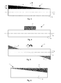
- Figs. 3, 4 and 5 show the tubular blank 6 of Fig. 2A in cross-section along the axis 8, with several variations for the flange 5. It should be appreciated that such variations can also be applied for other tubular blanks 6, such as those illustrated in Figs. 2B and 2C.
- the length L of the flange 5 varies along the length of the tubular blank 6. In this way the flange 5 can be provided only on locations on the tubular blank 6 where other parts are to be attached. Accordingly the flange 5 is omitted at other locations on the blank 6 where it is not required.
- Fig. 4 the flange 5 is only present along a part of the length of the tubular blank.
- the planar blank 1 of Fig. 1 may be pre-formed to obtain the flange 5 at a pre-determined location.
- Fig. 5 the direction P of the flange 5 varies along the length of the tubular blank, wherein the flange 5 spirals over the surface of the tubular blank 6.
- This embodiment may e.g. be obtained by forming the substantially planar blank 1 in a spiral wise fashion.
- the planar blank 1 may e.g. be formed to obtain a tubular blank 6 enclosing a volume with a varying diameter, such as a conical volume.
- the length L of the flange 5 may vary contrary to the diameter of the tubular blank 6. This is shown in Fig. 6.
- tubular blanks produced by the process described above are preferably modified by hydro-formation to arrive at a blank with a suitable shape that comprises a flange 5.
- Such tubular blanks may e.g. be used in the automotive industry, such as the A-pillar of a cabriolet.
- the flange 5 of the tubular blank can be used to attach further components to the blank, such as strengthening parts or sealing rubbers.
Landscapes
- Engineering & Computer Science (AREA)
- Mechanical Engineering (AREA)
- Physics & Mathematics (AREA)
- Fluid Mechanics (AREA)
- Shaping Metal By Deep-Drawing, Or The Like (AREA)
- Body Structure For Vehicles (AREA)
Priority Applications (1)
| Application Number | Priority Date | Filing Date | Title |
|---|---|---|---|
| EP05075850A EP1586391A1 (de) | 2004-04-13 | 2005-04-13 | Rohrförmiger Rohling und Verfahren zu seiner Herstellung |
Applications Claiming Priority (3)
| Application Number | Priority Date | Filing Date | Title |
|---|---|---|---|
| EP04076101A EP1586390A1 (de) | 2004-04-13 | 2004-04-13 | Rohrförmiger Rohling und Verfahren zu seiner Herstellung |
| EP04076101 | 2004-04-13 | ||
| EP05075850A EP1586391A1 (de) | 2004-04-13 | 2005-04-13 | Rohrförmiger Rohling und Verfahren zu seiner Herstellung |
Publications (1)
| Publication Number | Publication Date |
|---|---|
| EP1586391A1 true EP1586391A1 (de) | 2005-10-19 |
Family
ID=35058234
Family Applications (1)
| Application Number | Title | Priority Date | Filing Date |
|---|---|---|---|
| EP05075850A Withdrawn EP1586391A1 (de) | 2004-04-13 | 2005-04-13 | Rohrförmiger Rohling und Verfahren zu seiner Herstellung |
Country Status (1)
| Country | Link |
|---|---|
| EP (1) | EP1586391A1 (de) |
Cited By (4)
| Publication number | Priority date | Publication date | Assignee | Title |
|---|---|---|---|---|
| DE102008033114A1 (de) * | 2008-07-15 | 2010-01-21 | Bayerische Motoren Werke Aktiengesellschaft | Verfahren zur Herstellung eines Rohrs |
| CN103317312A (zh) * | 2013-07-09 | 2013-09-25 | 武汉钢铁(集团)公司 | 一种带翅方矩形钢管的制造方法 |
| CN104180152A (zh) * | 2014-08-21 | 2014-12-03 | 宋宇光 | 异型支撑用om形管 |
| CN104180153A (zh) * | 2014-08-21 | 2014-12-03 | 杜伟 | 异型支撑用9字形管 |
Citations (6)
| Publication number | Priority date | Publication date | Assignee | Title |
|---|---|---|---|---|
| US1608905A (en) * | 1924-06-18 | 1926-11-30 | Joseph B Murray | Heat-conducting tube and method of making the same |
| US4732819A (en) * | 1983-05-07 | 1988-03-22 | Honda Giken Kogyo Kabushiki Kaisha | Light-weight vehicle frame structure |
| DE4141867A1 (de) * | 1991-12-18 | 1993-06-24 | Welser Ohg Josef | Verfahren zum herstellen eines hohlprofils aus metallband |
| WO1998024569A1 (de) * | 1996-12-03 | 1998-06-11 | Elpatronic Ag | Verfahren zur herstellung eines formteiles sowie nach diesem hergestelltes formteil |
| US5836189A (en) * | 1996-02-07 | 1998-11-17 | Benteler Ag | Method of manufacturing a pipe having sections with different cross-sectional configurations |
| EP1172281A1 (de) * | 2000-07-14 | 2002-01-16 | Benteler Ag | A-Säulengestaltung eines Personenkraftwagens und Verfahren zur Herstellung einer A-Säule |
-
2005
- 2005-04-13 EP EP05075850A patent/EP1586391A1/de not_active Withdrawn
Patent Citations (6)
| Publication number | Priority date | Publication date | Assignee | Title |
|---|---|---|---|---|
| US1608905A (en) * | 1924-06-18 | 1926-11-30 | Joseph B Murray | Heat-conducting tube and method of making the same |
| US4732819A (en) * | 1983-05-07 | 1988-03-22 | Honda Giken Kogyo Kabushiki Kaisha | Light-weight vehicle frame structure |
| DE4141867A1 (de) * | 1991-12-18 | 1993-06-24 | Welser Ohg Josef | Verfahren zum herstellen eines hohlprofils aus metallband |
| US5836189A (en) * | 1996-02-07 | 1998-11-17 | Benteler Ag | Method of manufacturing a pipe having sections with different cross-sectional configurations |
| WO1998024569A1 (de) * | 1996-12-03 | 1998-06-11 | Elpatronic Ag | Verfahren zur herstellung eines formteiles sowie nach diesem hergestelltes formteil |
| EP1172281A1 (de) * | 2000-07-14 | 2002-01-16 | Benteler Ag | A-Säulengestaltung eines Personenkraftwagens und Verfahren zur Herstellung einer A-Säule |
Cited By (4)
| Publication number | Priority date | Publication date | Assignee | Title |
|---|---|---|---|---|
| DE102008033114A1 (de) * | 2008-07-15 | 2010-01-21 | Bayerische Motoren Werke Aktiengesellschaft | Verfahren zur Herstellung eines Rohrs |
| CN103317312A (zh) * | 2013-07-09 | 2013-09-25 | 武汉钢铁(集团)公司 | 一种带翅方矩形钢管的制造方法 |
| CN104180152A (zh) * | 2014-08-21 | 2014-12-03 | 宋宇光 | 异型支撑用om形管 |
| CN104180153A (zh) * | 2014-08-21 | 2014-12-03 | 杜伟 | 异型支撑用9字形管 |
Similar Documents
| Publication | Publication Date | Title |
|---|---|---|
| US6842957B2 (en) | Process for producing a tubular component | |
| EP0620056B1 (de) | Verfahren zum Formen eines rohrförmigen Konstruktionsteils | |
| US6302478B1 (en) | Hydroformed space frame joints therefor | |
| US8171769B2 (en) | Method of forming a flanged tubular member in hydroforming | |
| EP1210189B1 (de) | Verstärkter durch innenhochdruck geformter gegenstand und verfahren zur herstellung | |
| US6817382B2 (en) | Pile member | |
| US20020162224A1 (en) | Hydroformed vehicle frame assembly and method | |
| US9033398B2 (en) | Multi-thickness tube for hydroformed members | |
| KR20100097055A (ko) | 비틀림 프로파일 형상의 자동차부품을 제조하기 위한 방법 | |
| CN1418136A (zh) | 具有液压成形互连件的管状组件及其制造方法 | |
| US20110162431A1 (en) | Partially reinforced hollow profile | |
| US7484298B2 (en) | Method for forming a complex-shaped tubular structure | |
| US20060096099A1 (en) | Automotive crush tip and method of manufacturing | |
| US6941786B1 (en) | Component specific tube blanks for hydroforming body structure components | |
| EP1586391A1 (de) | Rohrförmiger Rohling und Verfahren zu seiner Herstellung | |
| JP5530168B2 (ja) | パイプ部材の成形方法 | |
| EP1586390A1 (de) | Rohrförmiger Rohling und Verfahren zu seiner Herstellung | |
| US6112567A (en) | Method and apparatus for manufacturing a hollow body from a tubular blank by internal high-pressure shaping | |
| JP2006143198A (ja) | 車両用ハイドロフォーム・カウル構造、ハイドロフォーム・カウルを持つ車体及びその組立方法 | |
| US20050244666A1 (en) | Tubular blank | |
| EP1814771A2 (de) | Knautschspitze für auto und herstellungsverfahren | |
| JP2010101008A (ja) | 円形鋼管用金属製中空ジョイント、金属製中空ジョイントの製造方法及びこれを用いた円形鋼管部材 | |
| EP1698410B1 (de) | Rohr zum Innenhochdruckumformen sowie Verfahren zum Innenhochdruckumformen eines Rohres | |
| EP1595611A2 (de) | Rohrförmiger rohling | |
| US20050223768A1 (en) | Method for manufacturing a metal tubular blank, a tubular blank, and a product produced from said tubular blank |
Legal Events
| Date | Code | Title | Description |
|---|---|---|---|
| PUAI | Public reference made under article 153(3) epc to a published international application that has entered the european phase |
Free format text: ORIGINAL CODE: 0009012 |
|
| AK | Designated contracting states |
Kind code of ref document: A1 Designated state(s): AT BE BG CH CY CZ DE DK EE ES FI FR GB GR HU IE IS IT LI LT LU MC NL PL PT RO SE SI SK TR |
|
| AX | Request for extension of the european patent |
Extension state: AL BA HR LV MK YU |
|
| AKX | Designation fees paid | ||
| REG | Reference to a national code |
Ref country code: DE Ref legal event code: 8566 |
|
| STAA | Information on the status of an ep patent application or granted ep patent |
Free format text: STATUS: THE APPLICATION IS DEEMED TO BE WITHDRAWN |
|
| 18D | Application deemed to be withdrawn |
Effective date: 20060420 |