EP1585359B1 - Remote control of phantom power supplied microphones - Google Patents
Remote control of phantom power supplied microphones Download PDFInfo
- Publication number
- EP1585359B1 EP1585359B1 EP04450074.2A EP04450074A EP1585359B1 EP 1585359 B1 EP1585359 B1 EP 1585359B1 EP 04450074 A EP04450074 A EP 04450074A EP 1585359 B1 EP1585359 B1 EP 1585359B1
- Authority
- EP
- European Patent Office
- Prior art keywords
- microphone
- voltage
- frequency
- power supply
- audio
- Prior art date
- Legal status (The legal status is an assumption and is not a legal conclusion. Google has not performed a legal analysis and makes no representation as to the accuracy of the status listed.)
- Expired - Lifetime
Links
Images

Classifications
-
- H—ELECTRICITY
- H04—ELECTRIC COMMUNICATION TECHNIQUE
- H04R—LOUDSPEAKERS, MICROPHONES, GRAMOPHONE PICK-UPS OR LIKE ACOUSTIC ELECTROMECHANICAL TRANSDUCERS; ELECTRIC HEARING AIDS; PUBLIC ADDRESS SYSTEMS
- H04R1/00—Details of transducers, loudspeakers or microphones
- H04R1/02—Casings; Cabinets ; Supports therefor; Mountings therein
- H04R1/04—Structural association of microphone with electric circuitry therefor
Definitions
- the invention relates to a circuit for the remote control of microphones.
- the power supply of microphones is conventionally provided by a power supply source, for example, using a mixer.
- a power supply source for example, using a mixer.
- the positive pole of the feed voltage is applied through two identical feeder resistances through two cable conductors of the audio cable.
- the return of the current occurs through a third conductor connected to pin 1 of an XLR plug.
- the current consumption of the microphone should be as small as possible to prevent an excessively large voltage drop at the feeder resistances.
- the maximum current consumption with 48-V capacitor microphones is 10 mA.
- the phantom power supply is here standardized according to DIN EN 61938 (formerly IEC 268).
- the microphone membrane To generate the polarization voltage on the microphone membrane, whose value is usually in the range of 20-100 volts dc, one uses primarily combinatorial circuit parts or voltage converters.
- the remaining microphone electronics are usually supplied with power by a linear regulation, which maintains either the supply feed voltage or the supply current at a predetermined value.
- this type of power supply is appropriate.
- the linear regulation becomes problematic when the power consumption in the microphone increases, for example, by the use of processors, A/D converters, LED displays, etc. In this case, a large portion of the energy that is made available by the phantom power supply is destroyed in the linear regulation elements.
- the phantom power supply since, according to the standard, the phantom power supply is limited in its current by the feeder resistances, the maximum supply voltage for the audio amplifier immediately decreases due to the linear regulation in the microphone, which results in a reduction of the maximal audio output voltage of the microphone.
- microphones there is an increasing need to be able to regulate or to change important microphone parameters via remote control. These parameters include the polarization voltage on the membrane and the associated sensitivity of the capacitor microphone, the directional characteristic of the microphone, the type of the phantom power supply (12 V, 24 V or 48 V), a series number, calibration data from the manufacturer, as well as a weakening of the signal and a connectable filter for the audio signal.
- DE 3 933 870 A1 discloses a method for the remote control of microphone parameters, such as directional characteristic, step sound filter, or preliminary damning.
- the supply voltage transferred to the cable conductor is regulated via a remote control unit, for example, in the mixing table, in such a manner that its amount represents control information for the microphone.
- the supply voltage is uncoupled and applied to an evaluation circuit, which generates a control signal as a function of the amount of the supply voltage.
- the power made available by the phantom power supply is optimally used and converted into the operational voltages required for the individual output receives, such as audio amplifier, microphone capsule, processors, controller, A/D converter, LED displays, etc.
- the goal is to be able to use as large as possible a proportion of the power made available by the phantom power supply for supplying the audio amplifier.
- a microphone comprising a power supply circuit for the individual power receivers, which microphone is characterized in that the power supply circuit comprises a control unit that converts the direct current transmitted via the cable conductors of the audio cable into an alternating current, a transformer connected to the control unit, and supply loops for the individual power receivers, where supply loops are inductively coupled by means of separate windings on the transformer to the alternating current generated by the control unit and to each other.
- a power supply circuit for example, a DC/DC converter, which has the following properties.
- the power supply circuit is regulated or operated in such a manner that there is a power adaptation to the phantom power unit. Therefore, the maximum possible power that the phantom power unit makes available can always be consumed by the power supply circuit of the microphone.
- the primary current consumption of the power supply circuit is constant. The power supply circuit therefore behaves, with the respect to the phantom power unit, as a constant-current sink.
- the individual supply loops for the individual power receivers are uncoupled in the power supply circuit by means of a transformer, to satisfy the different requirements of the individual power receivers: high voltages and small currents for polarization voltage, moderate voltage, and moderate current consumption for the audio amplifier, as well as small voltages and large currents for the digital electronics, with as little power loss as possible.
- a capacitor microphone according to the invention uses the presented power supply concept, the electrical power made available by the phantom power unit is optimally used.
- microphones can be fitted with new functions (for example, remote control, new operating concept, automatic compensation possibilities, etc.) while the maximal audio output voltage of the microphone remains the same.
- the generation of the essentially power-free polarization voltage occurs practically as a secondary product by a simple additional winding on the transformer.
- An additional advantage is that as a result of the use of as high an ohm level as possible, with a constant power source at the input of the power supply circuit, the switch ripple of the power supply circuit or of the DC/DC converter can very easily be filtered out.
- a frequency-modulated voltage is overlaid on the supply voltage of the phantom power supply.
- a data transfer occurs from a transmitter, which is arranged, for example, in the mixing table or in a device before the mixing table, via the audio lines to the microphone.
- the carrier frequency for the FSK modulation here is higher than the audio frequency range to be transmitted by the microphone.
- the carrier frequencies for the modulation are preferably approximately 100 kHz, and they can be separated from the audio signal using filters.
- a capacitor microphone characterized in that the capacitor microphone comprises at least one circuit for regulating the polarization voltage, where the circuit for the regulation of the polarization voltage comprises an analog regulation loop supplied with an unregulated voltage, and a digital regulation loop, in that the digital regulation loop comprises a control electronics, for example a microcontroller or a CPLD, that provides, to the analog regulation loop, a desired value for the polarization voltage, which is calculated using correction factors, and in that, for the purpose of feedback, the output of the analog regulation loop is connected with a control electronics.
- the capacitor microphone comprises at least one circuit for regulating the polarization voltage
- the circuit for the regulation of the polarization voltage comprises an analog regulation loop supplied with an unregulated voltage
- a digital regulation loop in that the digital regulation loop comprises a control electronics, for example a microcontroller or a CPLD, that provides, to the analog regulation loop, a desired value for the polarization voltage, which is calculated using correction factors, and in that, for the purpose of feedback, the output of the analog regulation loop is
- the polarization voltage is adjusted by a voltage regulation loop that is integrated in the microphone.
- the desired value of the polarization voltage is preestablished in this circuit via a D/A converter by a control electronics.
- the desired value of the polarization voltage can also be transmitted by remote control to the control electronics.
- the tolerance of the obtained polarization voltage now depends on the tolerance and the thermal behavior of a reference voltage source.
- the regulation of the polarization voltage via a digitally controlled regulation loop in the microphone allows a very precise, interference-resistant, and remote-controllable adjustment of the polarization voltage of capacitor microphones.
- the remote-controllable adjustment of the polarization voltage has the advantage that readjustments by fixed resistances or trim resistances are no longer necessary; this fact has a positive effect with respect to cost.
- the different microphone sensitivities can be compensated for and the required correction factors needed to compensate the polarization voltage can be stored.
- the polarization voltage can be calibrated during an acoustical measurement with closed microphone, and correction factors can again be stored.
- the microphone can acoustically follow moving actors, for example, in the performance of an opera.
- a capacitor microphone according to the invention allows an aging-caused recalibration of the microphone sensitivity, without having to disassemble the microphone, which again means a cost saving for the customer.
- the original sensitivity of the microphone can thus be readjusted later, that is, after the incorporation, by remote control.
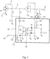
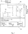
- Fig. 1 is a block diagram that shows the principal components of a microphone according to the invention.
- the phantom power supply of the microphone shown in Fig. 5 , is carried out by a phantom supply unit 31 through feeder resistances 32, 33 of identical magnitude, which are arranged behind the 3-pole plug 4, for example, an XLR plug, in or before the mixing table.
- a phantom power supply is shown in Fig. 5 .
- the associated values of the feeder resistances for a 12-V, 24-V, or 48-V supply are 680 S2, 1.2 kS2, or 6.8 k ⁇ , respectively.
- the lines 1 and 2 here represent cable conductors supplied by the phantom supply unit; line 3 represents the ground line that is usually connected to the grounded cable shielding.
- line 3 represents the ground line that is usually connected to the grounded cable shielding.
- the resistances 5 and 6 are the feeder resistances in the microphone. They are used for decoupling the power supply of the microphone from the output of the audio amplifier 10.
- the feeder resistances of the microphones 5 and 6 are assigned as additional internal resistances of the phantom power supply 31. Power adaptation exists when the internal resistance of the phantom power unit is identical to the internal resistance of the power supply circuit 11 in the microphone.
- the power supply circuit 11 comprises a power source 13, a control unit 12, and a transformer 14 connected to the control unit 12.
- the control unit 12 with the transformer 14 forms a circuit unit, where the DC voltage is converted into AC voltage.
- the transformer is a part of the oscillation generating circuit.
- alternating current can also be generated by the control unit 12 independently of the transformer.
- the control unit 12 then consists of an oscillating circle that is independent of the transformer, and which generates alternating current.
- the transformer only serves the function of converting the alternating current into the individual output voltages.
- the AC signal has a frequency in the range of 100-130 kHz.
- the AC signal can also be freely oscillating; this represents the simplest embodiment possibility for such a circuit.
- the only important factor is that the frequency range of the AC signal must lie outside of the audio frequency range in order to not produce any interferences with the audio signal, which interferences cannot be eliminated by simple filtering.
- the frequency should also not be too high, because otherwise the degree of efficiency of the circuit decreases and transmission interferences can be expected.
- An additional advantage of using a frequency of 100-130 kHz is that this frequency can also be used as cycle pulse for a control electronics 39 that is provided in the microphone. As a result, the interfering signals generated by digital technology are minimized, because no additional mixed products are produced between the digital cycle time and the oscillation frequency of the DC/DC converter.
- the produced AC signal is applied to a transformer 14.
- a transformer 14 As a result of the individually separated windings on the transformer, separate current loops 15, 16, 17 are produced for supplying the individual energy-consuming parts.
- This uncoupling allows, with as small as possible a power loss, the simultaneous supply of consumers that require high voltages but low current, as well as consumers with high current consumption and low voltage.
- the diodes 18, 19, 20 and the capacitors 21, 22, 23 in the individual supply loops 15, 16, 17 represent a rectifier circuit for converting AC voltage into DC voltage.
- Supply loop 16 serves to supply the microphone capsule 9 with the polarization voltage, which is applied via a resistance 8 to the microphone capsule 9.
- the invention is of course not restricted to capacitor microphones, since any kind of microphones, in particular dynamic microphones, can be connected to a phantom power supply.
- the individual power receivers are supplied by the phantom power unit in the same way as shown in Figs. 1 and 2 . But in the case of dynamic microphones a polarisation voltage is not necessary, therefore supply loop 16 is not needed.
- a constant-current generator 13 at the input of the DC/DC converter ensures a constant primary current uptake.
- the constant-current generator 13, with respect to the phantom power unit 31, behaves like a constant-current sink and it represents a constant-current generator for the power supply circuit 11.
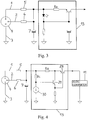
- An electrical component of this type is very well known to a person skilled in the art who is familiar with the state of the art. Circuit examples for constant-current generators from the state of the art are shown in Figs. 3 and 4. Fig.
- FIG. 3 shows a "transistor LED” constant-current generator with a bipolar transistor.
- the LED With this current generator, the LED is operated in the flow direction. As a result, a constant voltage is applied to the LED, with such a voltage also being applied to the series connection of the base emitter diode of the transistor with the emitter resistance.
- the circuit in Fig. 4 contains a constant-current generator with two counter coupled degenerated transistors 28, 29 with an additional integrated constant-current generator 30.
- This circuit is preferred because of better properties in view of a constant-current and a higher starting resistance.
- the current generator 30, at the preliminary resistance Rc generates a voltage drop that is equal to the voltage drop U Rc at the emitter resistance Re of the transistor 28.
- the transistor 29 forms, with transistor 28, a counter coupled degenerate system that ensures identical voltage drops at the resistances Rc and Re. As a result, the current I of the current generator is also kept constant.
- the current of the current generator 30 is therefore smaller by a factor of 100 than the constant-current that finally flows into the DC/DC converter 11.
- constant-current generators can also be provided, for example, a current generator with an inverted operation amplifier, Howland current generators, etc.
- the supply voltage generated by the power supply circuit 11 for the audio amplifier 10 is not regulated in a preferred embodiment.
- a regulation circuit 47, 48 is provided between diode 18 and resistance 8, comprising of a digital regulation loop 47 and an analog regulation loop 48, provided for the polarization voltage applied to the microphone capsule 9.
- Fig. 6 in combination with Fig. 7 illustrates such a preferably remote controllable, regulation circuit 47, 48.
- the control signals required for the regulation of the polarization voltage can be transmitted through at least one of the two cable conductors 1, 2.
- the detailed structure and the method of operation of such a regulation circuit 47, 48 are described further below.
- no regulation circuit is provided in the supply loop 15 for the audio amplifier 10.
- the entire power - which is not used for other circuit parts, such as processors, control electronics 39, polarization voltage at the microphone capsule 9, A/D or D/A converter 44, 46, LED displays 25 - is available for the audio amplifier 10.
- a high maximal audio output voltage can be achieved in a current-saving design of the audio amplifier 10, to achieve a high maximal audio output voltage.
- the supply voltage for the audio amplifier 10 as a result can also exceed the voltage made available by the phantom power supply. Because of the method of action of the power supply circuit 11, it is also possible to produce very simple positive and negative supply voltages for the audio amplifier 10. As a result, the audio amplifier 10 can also use grounding as the rest potential. The supply feed voltage of the audio amplifier (10) can therefore be symmetrically with respect to the grounding.
- the DC/DC converter 11 of the above described type works with a degree of efficiency of approximately 82%. Because, even in the most advantageous case, power is lost at DC/DC converters, it is advantageous to series-connect, if possible, the consumers to the DC/DC converter. As a result of the use of a constant-current generator 13, it is easily possible to connect consumers with constant-current consumption, for example, a logic supply 24, to make available a fixed direct current, for example, for a control electronics 39, or LED display 25, A/D or D/A converter 44, 46, etc., in series to the DC/DC converter 11.
- constant-current generator 13 it is easily possible to connect consumers with constant-current consumption, for example, a logic supply 24, to make available a fixed direct current, for example, for a control electronics 39, or LED display 25, A/D or D/A converter 44, 46, etc., in series to the DC/DC converter 11.
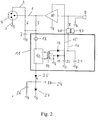
- FIG. 2 A corresponding embodiment of the power supply circuit 11 is shown in Fig. 2 .
- the difference, compared to Fig. 1 is that only the polarization voltage and the voltage for the audio amplifier 10 are generated through the DC/DC converter.
- the other consumers like the logic supply 24 for making available a fixed predetermined direct current, for example, for a control electronics 39, or LED displays 25, are series-connected to the DC/DC converter.
- the series-connected DC/DC converter 11 for the digital supply acts as an active load resistance, where the energy used at this resistance is not converted into heat but, in a majority proportion, is converted to a usable supply power for the audio amplifier 10 and the polarization voltage on the microphone capsule 9.
- a Zener diode 27 is provided, which is particularly well suited for stabilizing the voltage. Through this diode 27, any current that is not consumed, but delivered by the constant-current generator 13, is released to the grounding. In principle, one can use, instead of the Zener diode 27, any other constant-current generator or a shunt regulator.
- the released power is the product of the current of the constant-current generator 13 and the voltage applied to the power supply circuit 11.
- the entire voltage is applied to the DC/DC converter 11 and all the voltages are generated through the DC/DC converter.
- the voltage is divided into a portion that is applied to the DC/DC converter 11 and a second portion that is applied to the LEDs 25 and the digital supply.
- the DC/DC converter represents an active preliminary resistance for the LEDs 25 or the digital supply. Since the current consumption of the digital supply is not constant, but the current I is kept constant by the current generator 13, the excess current that exists, depending on the state of operation of the digital electronics, has to be bled off through the Zener diode 27.
- the power P I x voltage available at the DC/DC converter x degree of efficiency of the DC/DC converter is available.
- the power P I x voltage at the digital electronics and LEDs is available.
- the current consumption of the audio amplifier 10, in the uncontrolled state is approximately 0.8 mA
- the current consumption of the digital electronics is approximately 4.2 mA.
- the current generator 13 delivers a constant-current of approximately 4.7 mA.
- This voltage is much higher than the voltage of 24 V delivered by the phantom power supply unit 31 during power adaptation.
- the polarization voltage is also generated on the membrane of the capsule 9, the value of the supply voltage of the audio amplifier 10, which is actually reached, is slightly lower than this value, but still much higher than the 24 V available without the DC/DC converter.
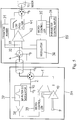
- Fig. 5 shows a microphone 54, which is connected with a transmitter or a remote control unit 55.
- the remote control of important microphone parameters here occurs directly through the audio cable, that is, through the lines 1, 2.
- the control unit 55 is preferably on the mixer, or arranged in front of it.
- a microcontroller 35 with a parameter control input 34 controls a frequency modulator 36, which feeds a frequency-modulated signal with the same level into the two cable conductors 1, 2 of the audio cable.
- the frequency-modulated signal can then be suppressed as a common mode signal in the input-difference amplifier 42.
- a supply voltage of a phantom power unit 31 is applied through the feeder resistances 32, 33 to the two cable conductors 1, 2.
- the frequency-modulated signal is applied to only one of the conductors of the audio cable, namely, to the conductor 2, which is not intended for the audio signal.
- the frequency-modulated signal is generated by FSK (frequency shift keying) or CPFSK (continuous phase FSK). Both modulations are procedures that are known from digital data transfer technology. In principle, it also possible to use ASK (amplitude shifting keying) or PSK (phase shift keying) modulation. However, ASK is much more likely to be subject to interferences, and PSK modulation is more difficult to carry out from the point of view of circuit technology. In contrast to the known applications of the above-mentioned methods, in the case of use in microphones, the crucial factor is that the modulated signal has to be separated from an analog signal, the audio signal.
- FSK frequency shift keying
- CPFSK continuous phase FSK
- the frequency-modulated voltage is separated by means of a filter 37, for example, a band pass filter, from the audio signals, and the control information contained therein is evaluated by means of a control electronics 39, for example a microcontroller or a CPLD (Complex Programmable Logic Device). Cable conductor 2 is uncoupled through a capacitance 43 from the grounding.
- the control electronics 39 is connected in front of a comparator 38 which functions as a voltage comparator. Commands through the outputs of the control electronics 39, for example, reach a power supply circuit 11, as can be seen in Figs. 1 and 2 , the audio amplifier 10, processors, control electronics 39, A/D or D/A converters 44, 46, etc.
- the frequency modulation on the two audio lines 1, 2 is carried out in the remote control unit 55, which is preferably located close to the mixing table.
- the remote control unit 55 on the one hand, the carrier frequency has to be applied in the direction toward the microphone 54, and, on the other hand, in the direction of the mixing table, all modulation frequencies have to be suppressed. Only the audio signals that come from the microphone 54 must be transmitted. To make the suppression of the modulation frequencies simpler, the modulation is carried out on both audio lines 1, 2 with the same level.
- the frequency-modulated signal appears as a common mode signal for the input-difference amplifier 42 and thus it can, as a common mode signal, be appropriately suppressed.
- the frequency modulation occurs only in the line that does not transit an audio signal, that is, line 2.
- the frequency-modulated signals can be eliminated by filtering through a low-pass filter 41.
- the data-acknowledge message can also be a frequency-modulated signal.
- the data-acknowledge message for the function of the remote control is not absolutely necessary; however, it increases the reliability of the system at the cost of additional electronics.
- Fig. 6 shows a capacitor microphone according to the invention, in which the regulation of the polarization voltage occurs by means of a two-step control regulation loop.
- a second digital regulation loop 47 is overlain above an internal analog regulation loop 48.
- a preferably frequency-modulated signal with control information which is transmitted through the cable conductors, which are also connected to the phantom power unit 31, reaches the control electronics 39 through a filter 37 and a comparator 38.
- the control of the control electronics 39 can also occur via regulating devices or operating elements on the microphone itself. It is also possible, that the control electronics is connected to a radio or an infrared interface for the purpose wireless transmission or to a cable interface.
- the desired value obtained in the control signal for the polarization voltage is delivered to the analog regulation 48 via a D/A converter 46 by the control electronics 39.
- Fig. 7 is an embodiment example, showing how the control electronics 39, which is for example a microcontroller or a CPLD, plus D/A converter or PWM 46 acts on an analog regulation loop 48.
- the analog regulation loop 48 comprises a regulation circuit 56 and a voltage divider 49, 50. The details of the regulation circuit 56 or of the overall analog regulation loop 48 are shown in Fig. 7 .
- the analog regulation loop 48 is preferably supplied by a power supply circuit 11 with an unregulated voltage of approximately 100-120 V.
- the DC/DC converter can be of the same type as described above, or represented in Figs 1 and 2 .
- the resistances 5 and 6 are the feeder resistances in the microphone. They are used for uncoupling the power supply of the microphone from the output of the audio amplifier 10.
- the resistances 5 and 6 are identical in size to preserve the symmetry of the lines 1 and 2.
- the invention is of course not restricted to phantom power supplied capacitor microphones.
- the energy supply for the individual power receivers of the capacitor microphone can, for example, also be carried out by a battery located in the microphone.
- the desired value provided by the D/A converter or the PWM 46, or, more precisely, the correction value for the polarization voltage, is compared with the actual value via the operation amplifier 52.
- the desired value is calculated from calibration data measured during the manufacture of the microphone and programmed into the control electronics.
- As a reference value for this calculation one uses either an exact reference voltage 45 on the conductor or a reference voltage programmed during the print measurement into the control electronics.
- the reference voltage 45 can be made available, for example, by a logic supply 24.
- Such a logic supply 24, which is preferably fed by a DC/DC converter 11, not shown in Fig. 7 is shown in Figs. 1 and 2 .
- a preferred embodiment provides a low pass filter 51 between D/A converter or PWM 46 and the input of the analog regulation loop 48, as represented in Fig. 7 .
- the actual value generated by the analog regulation loop 48 is taken up through a voltage divider 49, 50 and applied via an impedance converter 53 to the inverted input of the operation amplifier 52.
- the feedback line plus impedance converter is not included in the schematic drawing of Fig. 6 .
- this voltage is also applied to the input of an A/C converter 44 of the digital regulation loop 47.
- the resulting digital signal is made available to the control electronics 39 as feedback. As a result, the outer digital regulation loop 47 is closed.
- the voltage divider through which the actual value is taken up, is represented by the resistances 49, 50.
- A/D converter 44, control electronics 39, as well as D/A converter 46 can also be integrated in a single component.
- the correction voltages or the corresponding correction factors that are required to calculate a regulated and interference-free polarization voltage can correspond to different settings, which reflect certain sensitivities, guide characteristics, and aging parameters; they can be stored in a memory provided in the control electronics 39, and called up at any time.
- the invention is not limited to the individual embodiment examples. Naturally, it is also conceivable to use microphones in which all or at least some of the above-described circuits are combined.
- a remote control for all remote-controllable components can be provided in the microphone; also, the power supply circuit 11 can supply all conceivable power receivers in the microphone.
Landscapes
- Physics & Mathematics (AREA)
- Engineering & Computer Science (AREA)
- Acoustics & Sound (AREA)
- Signal Processing (AREA)
- Circuit For Audible Band Transducer (AREA)
- Electrostatic, Electromagnetic, Magneto- Strictive, And Variable-Resistance Transducers (AREA)
- Selective Calling Equipment (AREA)
Description
- The invention relates to a circuit for the remote control of microphones.
- The power supply of microphones is conventionally provided by a power supply source, for example, using a mixer. During phantom power supply, the positive pole of the feed voltage is applied through two identical feeder resistances through two cable conductors of the audio cable. The return of the current occurs through a third conductor connected to
pin 1 of an XLR plug. To be able to efficiently use the voltage supplied by the phantom power supply for the power supply of capacitor microphones, the current consumption of the microphone should be as small as possible to prevent an excessively large voltage drop at the feeder resistances. The maximum current consumption with 48-V capacitor microphones is 10 mA. The phantom power supply is here standardized according to DIN EN 61938 (formerly IEC 268). - To generate the polarization voltage on the microphone membrane, whose value is usually in the range of 20-100 volts dc, one uses primarily combinatorial circuit parts or voltage converters. The remaining microphone electronics are usually supplied with power by a linear regulation, which maintains either the supply feed voltage or the supply current at a predetermined value. For microphones with little power consumption, this type of power supply is appropriate. The linear regulation becomes problematic when the power consumption in the microphone increases, for example, by the use of processors, A/D converters, LED displays, etc. In this case, a large portion of the energy that is made available by the phantom power supply is destroyed in the linear regulation elements. However, since, according to the standard, the phantom power supply is limited in its current by the feeder resistances, the maximum supply voltage for the audio amplifier immediately decreases due to the linear regulation in the microphone, which results in a reduction of the maximal audio output voltage of the microphone.
- An additional problem consists of the generation of the polarization voltage. This voltage is usually applied through a high-ohm resistance to the microphone membrane. Here, the required power is very low. Voltage regulators with high efficiency for the generation of this practically powerless polarization voltage are also difficult to construct.
- An additional problem concerns the remote control of microphones. With microphones, there is an increasing need to be able to regulate or to change important microphone parameters via remote control. These parameters include the polarization voltage on the membrane and the associated sensitivity of the capacitor microphone, the directional characteristic of the microphone, the type of the phantom power supply (12 V, 24 V or 48 V), a series number, calibration data from the manufacturer, as well as a weakening of the signal and a connectable filter for the audio signal.
-
DE 3 933 870 A1 discloses a method for the remote control of microphone parameters, such as directional characteristic, step sound filter, or preliminary damning. In the process, the supply voltage transferred to the cable conductor is regulated via a remote control unit, for example, in the mixing table, in such a manner that its amount represents control information for the microphone. On the side of the microphone, the supply voltage is uncoupled and applied to an evaluation circuit, which generates a control signal as a function of the amount of the supply voltage. By this method of data transfer, only a small quantity of control information can be transmitted to the microphone, and therefore also only a few parameters can be remote-controlled in the microphone. - An additional, so far not optimally solved, problem concerns the polarization voltage generation on the membrane of a capacitor microphone. The level of the polarization voltage is incorporated directly in the level of sensitivity of the microphone capsule. As a result, it is also possible to regulate the sensitivity of capacitor capsules with the aid of the polarization voltage. This is of particular advantage in connection with the use of double membrane capsules, because these capsules not only allow the regulation of the sensitivity but also of the directional characteristic, in the case of a separate supply of the individual membranes with polarization voltage.
- It is known how to regulate the polarization voltage with the aid of fixed resistances or trim resistances. In the process, during the assembly of the microphone, a one-time adjustment of the polarization voltage occurs. The directional characteristic is here predetermined once with fixed resistance ratios. Using this method, the compensation of tolerances in the sensitivity that are caused by the assembly of the microphone capsules as well as by aging processes is only possible with difficulty. For this purpose, one would need a compensation of the polarization voltage during an acoustic measurement of the sensitivity in the assembled state of the microphone. It is also not possible to compensate for sensitivity tolerances in the case of different directional characteristics.
- In connection with the power supply of microphones, there is a need for a solution wherein the power made available by the phantom power supply is optimally used and converted into the operational voltages required for the individual output receives, such as audio amplifier, microphone capsule, processors, controller, A/D converter, LED displays, etc. Here, the goal is to be able to use as large as possible a proportion of the power made available by the phantom power supply for supplying the audio amplifier.
- According to the invention, these goals are achieved with a microphone comprising a power supply circuit for the individual power receivers, which microphone is characterized in that the power supply circuit comprises a control unit that converts the direct current transmitted via the cable conductors of the audio cable into an alternating current, a transformer connected to the control unit, and supply loops for the individual power receivers, where supply loops are inductively coupled by means of separate windings on the transformer to the alternating current generated by the control unit and to each other.
- In the process, all the voltages required for the above-mentioned power receivers are generated by a power supply circuit, for example, a DC/DC converter, which has the following properties. The power supply circuit is regulated or operated in such a manner that there is a power adaptation to the phantom power unit. Therefore, the maximum possible power that the phantom power unit makes available can always be consumed by the power supply circuit of the microphone. The primary current consumption of the power supply circuit is constant. The power supply circuit therefore behaves, with the respect to the phantom power unit, as a constant-current sink. The individual supply loops for the individual power receivers are uncoupled in the power supply circuit by means of a transformer, to satisfy the different requirements of the individual power receivers: high voltages and small currents for polarization voltage, moderate voltage, and moderate current consumption for the audio amplifier, as well as small voltages and large currents for the digital electronics, with as little power loss as possible.
- The advantageous effect of a capacitor microphone according to the invention is obvious: using the presented power supply concept, the electrical power made available by the phantom power unit is optimally used. As a result, microphones can be fitted with new functions (for example, remote control, new operating concept, automatic compensation possibilities, etc.) while the maximal audio output voltage of the microphone remains the same. The generation of the essentially power-free polarization voltage occurs practically as a secondary product by a simple additional winding on the transformer.
- An additional advantage is that as a result of the use of as high an ohm level as possible, with a constant power source at the input of the power supply circuit, the switch ripple of the power supply circuit or of the DC/DC converter can very easily be filtered out.
- With the increasing adaptation possibilities in the microphone, such as changing the polarization voltage and thus the sensitivity, continual changing of the directional characteristic of double membrane capsules and changing the control signals for microprocessors for storing calibration data, as well as modifications of the frequency range, the maximal audio output voltage, the amplification, or THD of the audio amplifier, there is a need for a substantially higher rate of data transfer to via a remote control to the microphone.
- The invention is defined by
independent method claim 1. Preferred embodiments are defined in the dependent claims. - In this method, a frequency-modulated voltage is overlaid on the supply voltage of the phantom power supply. A data transfer occurs from a transmitter, which is arranged, for example, in the mixing table or in a device before the mixing table, via the audio lines to the microphone. The carrier frequency for the FSK modulation here is higher than the audio frequency range to be transmitted by the microphone.
- By using frequency-modulated signal transmission, in contrast to transmission with direct current, a substantially higher data transfer rate can be achieved. As a result, using a certain protocol, a large number of parameters can be transmitted. The carrier frequencies for the modulation are preferably approximately 100 kHz, and they can be separated from the audio signal using filters.
- To satisfy the need for low tolerances in the polarization voltage of capacitor microphones - for example, in view of the sensitivity, a tolerance of z0.5 dB is sought - a solution is needed which allows a flexible adjustment of the polarization voltage even in the assembled state of the microphone.
- This is achieved by a capacitor microphone, characterized in that the capacitor microphone comprises at least one circuit for regulating the polarization voltage, where the circuit for the regulation of the polarization voltage comprises an analog regulation loop supplied with an unregulated voltage, and a digital regulation loop, in that the digital regulation loop comprises a control electronics, for example a microcontroller or a CPLD, that provides, to the analog regulation loop, a desired value for the polarization voltage, which is calculated using correction factors, and in that, for the purpose of feedback, the output of the analog regulation loop is connected with a control electronics.
- In this process, the polarization voltage is adjusted by a voltage regulation loop that is integrated in the microphone. The desired value of the polarization voltage is preestablished in this circuit via a D/A converter by a control electronics. As a result, a finely graded adjustment of the polarization voltage can be carried out. The desired value of the polarization voltage can also be transmitted by remote control to the control electronics. The tolerance of the obtained polarization voltage now depends on the tolerance and the thermal behavior of a reference voltage source.
- The regulation of the polarization voltage via a digitally controlled regulation loop in the microphone allows a very precise, interference-resistant, and remote-controllable adjustment of the polarization voltage of capacitor microphones. As a result, it becomes possible, during the manufacture and in the measurement-technological verification of capacitor microphones, to achieve very narrow tolerance requirements with respect to the sensitivity and directional characteristic. The remote-controllable adjustment of the polarization voltage has the advantage that readjustments by fixed resistances or trim resistances are no longer necessary; this fact has a positive effect with respect to cost. In comparison to the existing solutions with fixed set polarization voltages, the following additional possibilities arise in connection with the capacitor microphone according to the invention:
- As a function of the individual properties of double membrane capsules, in the case of differently regulated directional characteristics, the different microphone sensitivities can be compensated for and the required correction factors needed to compensate the polarization voltage can be stored.
- In combination with a remote control, as described above, for example, the polarization voltage can be calibrated during an acoustical measurement with closed microphone, and correction factors can again be stored.
- It is of particular advantage to have the possibility to vary the polarization voltage of a remote-controlled microphone and thus its directional effect during the operation. For example, the microphone can acoustically follow moving actors, for example, in the performance of an opera.
- A capacitor microphone according to the invention allows an aging-caused recalibration of the microphone sensitivity, without having to disassemble the microphone, which again means a cost saving for the customer. During the replacement of the microphone capsule, the original sensitivity of the microphone can thus be readjusted later, that is, after the incorporation, by remote control.
- Below, the invention is further explained with reference to drawings. In the drawings:
-
Fig. 1 shows a block diagram of a capacitor microphone according to the invention, with a power supply circuit, -
Fig. 2 shows a block diagram of an embodiment of a capacitor microphone according to the invention, with a power supply circuit, -
Fig. 3 shows a circuit diagram of a transistor-LED constant-power source according to the state of the art, -
Fig. 4 shows a circuit diagram of a constant-power source with counter-coupled transistors according to the state of the art, -
Fig. 5 shows a block diagram of a capacitor microphone, which is connected to a remote control unit, -
Fig. 6 shows a block diagram of a capacitor microphone with integrated circuit for adjusting the polarization voltage, and -
Fig. 7 shows the circuit for adjusting the polarization voltage, comprising an analog and a digital regulation loop. -
Fig. 1 is a block diagram that shows the principal components of a microphone according to the invention. The phantom power supply of the microphone, shown inFig. 5 , is carried out by aphantom supply unit 31 throughfeeder resistances pole plug 4, for example, an XLR plug, in or before the mixing table. Such a phantom power supply is shown inFig. 5 . According to the standard, three phantom power supplies are possible: the associated values of the feeder resistances for a 12-V, 24-V, or 48-V supply are 680 S2, 1.2 kS2, or 6.8 kΩ, respectively. Thelines line 3 represents the ground line that is usually connected to the grounded cable shielding. Through the audio cable, that is, throughlines resistances phantom power unit 31 is connected to the input of thepower supply circuit 11 according to the invention. Acapacitance 7 smoothes the supply voltage against the grounding. Theresistances audio amplifier 10. The feeder resistances of themicrophones phantom power supply 31. Power adaptation exists when the internal resistance of the phantom power unit is identical to the internal resistance of thepower supply circuit 11 in the microphone. Thus, in the case of power adjustment, half the voltage of the phantom power supply is the supply voltage for thepower supply circuit 11. This power, which is the maximum that can be produced by thephantom power unit 31, is now distributed through thepower supply circuit 11 in the form of a DC/DC converter to all energy-consuming parts in the microphone. The excess power is here made available to theaudio amplifier 10 to achieve as high as possible the maximum audio output voltage of the microphone. With regard to different power supply voltages (according to standard 12 V, 24 V, or 48 V), the circuit can be designed in such a manner that the power adaptation to different phantom power supplies occurs automatically. This task is then taken over by thecontrol unit 12 described below. - The
power supply circuit 11 comprises apower source 13, acontrol unit 12, and atransformer 14 connected to thecontrol unit 12. Thecontrol unit 12 with thetransformer 14 forms a circuit unit, where the DC voltage is converted into AC voltage. In this case, the transformer is a part of the oscillation generating circuit. Naturally, alternating current can also be generated by thecontrol unit 12 independently of the transformer. Thecontrol unit 12 then consists of an oscillating circle that is independent of the transformer, and which generates alternating current. The transformer only serves the function of converting the alternating current into the individual output voltages. - In a preferred embodiment, the AC signal has a frequency in the range of 100-130 kHz. The AC signal can also be freely oscillating; this represents the simplest embodiment possibility for such a circuit. The only important factor is that the frequency range of the AC signal must lie outside of the audio frequency range in order to not produce any interferences with the audio signal, which interferences cannot be eliminated by simple filtering. On the other hand, the frequency should also not be too high, because otherwise the degree of efficiency of the circuit decreases and transmission interferences can be expected.
- An additional advantage of using a frequency of 100-130 kHz is that this frequency can also be used as cycle pulse for a
control electronics 39 that is provided in the microphone. As a result, the interfering signals generated by digital technology are minimized, because no additional mixed products are produced between the digital cycle time and the oscillation frequency of the DC/DC converter. - The produced AC signal is applied to a
transformer 14. As a result of the individually separated windings on the transformer, separatecurrent loops diodes capacitors individual supply loops Supply loop 16 serves to supply themicrophone capsule 9 with the polarization voltage, which is applied via a resistance 8 to themicrophone capsule 9. - The invention is of course not restricted to capacitor microphones, since any kind of microphones, in particular dynamic microphones, can be connected to a phantom power supply. The individual power receivers are supplied by the phantom power unit in the same way as shown in
Figs. 1 and2 . But in the case of dynamic microphones a polarisation voltage is not necessary, thereforesupply loop 16 is not needed. - The use of a constant-
current generator 13 at the input of the DC/DC converter ensures a constant primary current uptake. The constant-current generator 13, with respect to thephantom power unit 31, behaves like a constant-current sink and it represents a constant-current generator for thepower supply circuit 11. A constant-current generator 13 having as high an ohm level as possible, among other effects, simplifies the filtering of the switching ripple produced during the DC/AC conversion and thus it simultaneously prevents the overlaying of interferences on the audio signal. An electrical component of this type is very well known to a person skilled in the art who is familiar with the state of the art. Circuit examples for constant-current generators from the state of the art are shown inFigs. 3 and 4. Fig. 3 shows a "transistor LED" constant-current generator with a bipolar transistor. With this current generator, the LED is operated in the flow direction. As a result, a constant voltage is applied to the LED, with such a voltage also being applied to the series connection of the base emitter diode of the transistor with the emitter resistance. The current delivered by this current generator therefore is I = (ULED-Ubc)/Re, where ULED is the voltage drop at the LED, Ubc is the base emitter voltage, and Re is the emitter resistance. - The circuit in
Fig. 4 contains a constant-current generator with two counter coupled degeneratedtransistors current generator 30. This circuit is preferred because of better properties in view of a constant-current and a higher starting resistance. Thecurrent generator 30, at the preliminary resistance Rc, generates a voltage drop that is equal to the voltage drop URc at the emitter resistance Re of thetransistor 28. The current of the constant-current generator here is I = URc/Re. Thetransistor 29 here forms, withtransistor 28, a counter coupled degenerate system that ensures identical voltage drops at the resistances Rc and Re. As a result, the current I of the current generator is also kept constant. The current of thecurrent generator 30 is therefore smaller by a factor of 100 than the constant-current that finally flows into the DC/DC converter 11. - Naturally, other types of constant-current generators can also be provided, for example, a current generator with an inverted operation amplifier, Howland current generators, etc.
- The supply voltage generated by the
power supply circuit 11 for theaudio amplifier 10 is not regulated in a preferred embodiment. In thesupply loop 16 for themicrophone capsule 9, aregulation circuit diode 18 and resistance 8, comprising of adigital regulation loop 47 and ananalog regulation loop 48, provided for the polarization voltage applied to themicrophone capsule 9.Fig. 6 in combination withFig. 7 illustrates such a preferably remote controllable,regulation circuit cable conductors regulation circuit Figs. 1 and2 , no regulation circuit is provided in thesupply loop 15 for theaudio amplifier 10. As a result, the entire power - which is not used for other circuit parts, such as processors,control electronics 39, polarization voltage at themicrophone capsule 9, A/D or D/A converter audio amplifier 10. As a result, a high maximal audio output voltage can be achieved in a current-saving design of theaudio amplifier 10, to achieve a high maximal audio output voltage. In principle, the supply voltage for theaudio amplifier 10 as a result can also exceed the voltage made available by the phantom power supply. Because of the method of action of thepower supply circuit 11, it is also possible to produce very simple positive and negative supply voltages for theaudio amplifier 10. As a result, theaudio amplifier 10 can also use grounding as the rest potential. The supply feed voltage of the audio amplifier (10) can therefore be symmetrically with respect to the grounding. - In a more advantageous embodiment, the DC/
DC converter 11 of the above described type works with a degree of efficiency of approximately 82%. Because, even in the most advantageous case, power is lost at DC/DC converters, it is advantageous to series-connect, if possible, the consumers to the DC/DC converter. As a result of the use of a constant-current generator 13, it is easily possible to connect consumers with constant-current consumption, for example, alogic supply 24, to make available a fixed direct current, for example, for acontrol electronics 39, orLED display 25, A/D or D/A converter DC converter 11. - A corresponding embodiment of the
power supply circuit 11 is shown inFig. 2 . The difference, compared toFig. 1 , is that only the polarization voltage and the voltage for theaudio amplifier 10 are generated through the DC/DC converter. The other consumers, like thelogic supply 24 for making available a fixed predetermined direct current, for example, for acontrol electronics 39, or LED displays 25, are series-connected to the DC/DC converter. The series-connected DC/DC converter 11 for the digital supply acts as an active load resistance, where the energy used at this resistance is not converted into heat but, in a majority proportion, is converted to a usable supply power for theaudio amplifier 10 and the polarization voltage on themicrophone capsule 9. - As shown in
Fig. 2 , in connection with alogic supply 24 for making available a reference voltage or additional digital electronics, aZener diode 27 is provided, which is particularly well suited for stabilizing the voltage. Through thisdiode 27, any current that is not consumed, but delivered by the constant-current generator 13, is released to the grounding. In principle, one can use, instead of theZener diode 27, any other constant-current generator or a shunt regulator. - The released power is the product of the current of the constant-
current generator 13 and the voltage applied to thepower supply circuit 11. In the block diagram ofFig. 1 , the entire voltage is applied to the DC/DC converter 11 and all the voltages are generated through the DC/DC converter. In the block diagram ofFig. 2 , the voltage is divided into a portion that is applied to the DC/DC converter 11 and a second portion that is applied to theLEDs 25 and the digital supply. The DC/DC converter represents an active preliminary resistance for theLEDs 25 or the digital supply. Since the current consumption of the digital supply is not constant, but the current I is kept constant by thecurrent generator 13, the excess current that exists, depending on the state of operation of the digital electronics, has to be bled off through theZener diode 27. For the supply of theaudio amplifier 10, the power P = I x voltage available at the DC/DC converter x degree of efficiency of the DC/DC converter is available. For the LEDs and the digital electronics, the power P = I x voltage at the digital electronics and LEDs is available. - For illustration, an example is given: The current consumption of the
audio amplifier 10, in the uncontrolled state, is approximately 0.8 mA, the current consumption of the digital electronics is approximately 4.2 mA. Thecurrent generator 13 delivers a constant-current of approximately 4.7 mA. Thus, in this special case, it is more advantageous to lead the voltage for the digital electronics, not through the DC/DC converter, but to use a series connection to the DC/DC converter. Moreover, in additional developments, it may turn out that, with regard to energy, it is more advantageous to lead all the required voltages, as in the solution shown in the block diagram ofFig. 1 , through the DC/DC converter. - The conversion of the supply voltage for the
audio amplifier 10 in this case leads to a maximum available power for the amplifier of: P = 4.7 mA x 18 V x 0.82 = 69 mW. The voltage at theaudio amplifier 10 thus is U = P/I = 69 mW/0.8 mA = 55 V. This voltage is much higher than the voltage of 24 V delivered by the phantompower supply unit 31 during power adaptation. However, since the polarization voltage is also generated on the membrane of thecapsule 9, the value of the supply voltage of theaudio amplifier 10, which is actually reached, is slightly lower than this value, but still much higher than the 24 V available without the DC/DC converter. -
Fig. 5 shows amicrophone 54, which is connected with a transmitter or aremote control unit 55. The remote control of important microphone parameters here occurs directly through the audio cable, that is, through thelines control unit 55 is preferably on the mixer, or arranged in front of it. Amicrocontroller 35 with aparameter control input 34 controls afrequency modulator 36, which feeds a frequency-modulated signal with the same level into the twocable conductors difference amplifier 42. At the same time, a supply voltage of aphantom power unit 31 is applied through thefeeder resistances cable conductors conductor 2, which is not intended for the audio signal. - In a preferred embodiment, the frequency-modulated signal is generated by FSK (frequency shift keying) or CPFSK (continuous phase FSK). Both modulations are procedures that are known from digital data transfer technology. In principle, it also possible to use ASK (amplitude shifting keying) or PSK (phase shift keying) modulation. However, ASK is much more likely to be subject to interferences, and PSK modulation is more difficult to carry out from the point of view of circuit technology. In contrast to the known applications of the above-mentioned methods, in the case of use in microphones, the crucial factor is that the modulated signal has to be separated from an analog signal, the audio signal. Even if the frequency-modulated signal is only fed into the
conductor 2, which is not intended for the audio signal, the capacitive coupling between the twoconductors - In the microphone, the frequency-modulated voltage is separated by means of a
filter 37, for example, a band pass filter, from the audio signals, and the control information contained therein is evaluated by means of acontrol electronics 39, for example a microcontroller or a CPLD (Complex Programmable Logic Device).Cable conductor 2 is uncoupled through acapacitance 43 from the grounding. Thecontrol electronics 39 is connected in front of acomparator 38 which functions as a voltage comparator. Commands through the outputs of thecontrol electronics 39, for example, reach apower supply circuit 11, as can be seen inFigs. 1 and2 , theaudio amplifier 10, processors,control electronics 39, A/D or D/A converters - The frequency modulation on the two
audio lines remote control unit 55, which is preferably located close to the mixing table. In theremote control unit 55, on the one hand, the carrier frequency has to be applied in the direction toward themicrophone 54, and, on the other hand, in the direction of the mixing table, all modulation frequencies have to be suppressed. Only the audio signals that come from themicrophone 54 must be transmitted. To make the suppression of the modulation frequencies simpler, the modulation is carried out on bothaudio lines remote control unit 55, as a result, the frequency-modulated signal appears as a common mode signal for the input-difference amplifier 42 and thus it can, as a common mode signal, be appropriately suppressed. In a second variant of the remote control, the frequency modulation occurs only in the line that does not transit an audio signal, that is,line 2. In the direction toward the mixing table, in this variant, the frequency-modulated signals can be eliminated by filtering through a low-pass filter 41. Thephantom power unit 31, including thefeeder resistances difference amplifiers 42 and low pass filters, do not have to be integrated, as shown inFig. 5 , in the remote control unit. For example, they can also be provided in the mixing table. - To ensure, during the transmission of a control signal from the
remote control unit 55 to themicrophone 54, that the control signal has in fact reached thecontrol electronics 39, the latter sends in response to the control signal a data-acknowledge message to theremote control unit 55. The data-acknowledge message can also be a frequency-modulated signal. The data-acknowledge message for the function of the remote control is not absolutely necessary; however, it increases the reliability of the system at the cost of additional electronics. - The above described method for remote control is of course not restricted to capacitor microphones, since the individual power receivers of any kind of microphones, in particular dynamic microphones, can be operated by means of a phantom power supply.
-
Fig. 6 shows a capacitor microphone according to the invention, in which the regulation of the polarization voltage occurs by means of a two-step control regulation loop. Here, a seconddigital regulation loop 47 is overlain above an internalanalog regulation loop 48. As a result, it becomes possible to generate a well-regulated, interference-free polarization voltage on themicrophone capsule 9. - A preferably frequency-modulated signal with control information, which is transmitted through the cable conductors, which are also connected to the
phantom power unit 31, reaches thecontrol electronics 39 through afilter 37 and acomparator 38. Detailed presentations concerning the remote control of microphones according to the invention have already been provided above. See also, in particular,Fig. 5 . The control of thecontrol electronics 39 can also occur via regulating devices or operating elements on the microphone itself. It is also possible, that the control electronics is connected to a radio or an infrared interface for the purpose wireless transmission or to a cable interface. The desired value obtained in the control signal for the polarization voltage is delivered to theanalog regulation 48 via a D/A converter 46 by thecontrol electronics 39. Instead of a D/A converter, one can also use a pulse-width modulation circuit (PWM). Although PWM circuits have lower conversion rates, they are inexpensive and therefore are very appropriate for adjusting constant levels in these converters.Fig. 7 is an embodiment example, showing how thecontrol electronics 39, which is for example a microcontroller or a CPLD, plus D/A converter orPWM 46 acts on ananalog regulation loop 48. Many analog regulation loops are known in the state of the art, and, for a person skilled in the art who knows the invention, it is easy to choose dimensions for such a regulation loop. As schematically represented inFig. 6 , theanalog regulation loop 48 comprises aregulation circuit 56 and avoltage divider regulation circuit 56 or of the overallanalog regulation loop 48 are shown inFig. 7 . - The
analog regulation loop 48 is preferably supplied by apower supply circuit 11 with an unregulated voltage of approximately 100-120 V. The DC/DC converter can be of the same type as described above, or represented inFigs 1 and2 . Theresistances audio amplifier 10. Theresistances lines - The invention is of course not restricted to phantom power supplied capacitor microphones. The energy supply for the individual power receivers of the capacitor microphone can, for example, also be carried out by a battery located in the microphone.
- The desired value provided by the D/A converter or the
PWM 46, or, more precisely, the correction value for the polarization voltage, is compared with the actual value via theoperation amplifier 52. The desired value is calculated from calibration data measured during the manufacture of the microphone and programmed into the control electronics. As a reference value for this calculation, one uses either anexact reference voltage 45 on the conductor or a reference voltage programmed during the print measurement into the control electronics. Thereference voltage 45 can be made available, for example, by alogic supply 24. Such alogic supply 24, which is preferably fed by a DC/DC converter 11, not shown inFig. 7 , is shown inFigs. 1 and2 . - To suppress the undesired influence of high-frequency interferences on the
analog regulation loop 48, a preferred embodiment provides alow pass filter 51 between D/A converter orPWM 46 and the input of theanalog regulation loop 48, as represented inFig. 7 . The actual value generated by theanalog regulation loop 48 is taken up through avoltage divider impedance converter 53 to the inverted input of theoperation amplifier 52. The feedback line plus impedance converter is not included in the schematic drawing ofFig. 6 . At the same time, this voltage is also applied to the input of an A/C converter 44 of thedigital regulation loop 47. The resulting digital signal is made available to thecontrol electronics 39 as feedback. As a result, the outerdigital regulation loop 47 is closed. InFig. 7 , the voltage divider, through which the actual value is taken up, is represented by theresistances Fig. 7 , A/D converter 44,control electronics 39, as well as D/A converter 46 can also be integrated in a single component. - As output of the
analog regulation 48, one obtains the regulated polarization voltage applied to themicrophone capsule 9 via a high-ohm resistance 8. The correction voltages or the corresponding correction factors that are required to calculate a regulated and interference-free polarization voltage can correspond to different settings, which reflect certain sensitivities, guide characteristics, and aging parameters; they can be stored in a memory provided in thecontrol electronics 39, and called up at any time. - These correction factors can later be changed by remote control with a closed microphone (for example, in the Service Department or by the distributor, and also possibly by the customer). Besides the possible correction of microphone properties resulting from aging or from the replacement of the microphone capsule, an on-site custom-specific tuning of the microphone is thus also possible.
- The invention is not limited to the individual embodiment examples. Naturally, it is also conceivable to use microphones in which all or at least some of the above-described circuits are combined. For example, a remote control for all remote-controllable components can be provided in the microphone; also, the
power supply circuit 11 can supply all conceivable power receivers in the microphone.
Claims (10)
- Method for a remote control of a microphone, which comprises at least one microphone capsule (9), and at least one additional power receiver, whose energy supply occurs by a phantom power unit (31) through two cable conductors (1, 2) of an audio cable, which energy supply is referred to as a phantom power supply, characterized in that a frequency-modulated voltage is applied as a frequency-modulated control signal to at least one of the two cable conductors (1, 2) through which the phantom power supply also occurs, and in that the frequency-modulated voltage, on the microphone side, is applied to a control electronics (39), which sends commands to said at least one additional power receiver according to the frequency-modulated control signal.
- Method according to Claim 1, characterized in that the at least one additional power receiver is selected from the group of audio amplifiers (10), power supply circuits (11), processors, control electronics (39), A/D and D/A converters (44, 46), LED displays (25).
- Method according to Claim 1 or 2, characterized in that the carrier frequencies for the control signal are approximately 100 kHz.
- Method according to one of Claims 1-3, characterized in that the audio signal is transmitted through the cable conductor (1) and the frequency-modulated voltage is fed into the cable conductor (2).
- Method according to one of Claims 1-3, characterized in that the frequency-modulated voltage is applied at the same level to both cable conductors (1, 2) as a common mode signal.
- Method according to Claim 5, characterized in that the frequency-modulated voltage is separated from the audio signal by an input-difference amplifier (42).
- Method according to one of Claims 1-6 characterized in that the frequency-modulated voltage is separated from the audio signal by a low-pass filter (41).
- Method according to one of Claims 1-7, characterized in that, in response to a control signal from a remote control unit (55) to the microphone (54), a data-acknowledge message is sent to the remote control unit.
- Method according to Claim 8, characterized in that the data-acknowledge message is also a frequency-modulated signal.
- Method according to one of Claims 1-9, characterized in that the control electronics (39) is a microcontroller or a CPLD, i.e. a complex programmable logic device.
Priority Applications (7)
| Application Number | Priority Date | Filing Date | Title |
|---|---|---|---|
| EP04450074.2A EP1585359B1 (en) | 2004-03-30 | 2004-03-30 | Remote control of phantom power supplied microphones |
| TW094109351A TWI358954B (en) | 2004-03-30 | 2005-03-25 | Remote control of phantom power supplied microphon |
| JP2005096493A JP4833572B2 (en) | 2004-03-30 | 2005-03-29 | Remote control of phantom powered microphones |
| US11/094,825 US7835531B2 (en) | 2004-03-30 | 2005-03-30 | Microphone system |
| US11/094,805 US7620189B2 (en) | 2004-03-30 | 2005-03-30 | Polarization voltage setting of microphones |
| US11/093,762 US7356151B2 (en) | 2004-03-30 | 2005-03-30 | Microphone system |
| CN2005100588508A CN1678135B (en) | 2004-03-30 | 2005-03-30 | Remote control of phantom power supplied microphones |
Applications Claiming Priority (1)
| Application Number | Priority Date | Filing Date | Title |
|---|---|---|---|
| EP04450074.2A EP1585359B1 (en) | 2004-03-30 | 2004-03-30 | Remote control of phantom power supplied microphones |
Publications (2)
| Publication Number | Publication Date |
|---|---|
| EP1585359A1 EP1585359A1 (en) | 2005-10-12 |
| EP1585359B1 true EP1585359B1 (en) | 2017-10-04 |
Family
ID=34896202
Family Applications (1)
| Application Number | Title | Priority Date | Filing Date |
|---|---|---|---|
| EP04450074.2A Expired - Lifetime EP1585359B1 (en) | 2004-03-30 | 2004-03-30 | Remote control of phantom power supplied microphones |
Country Status (4)
| Country | Link |
|---|---|
| EP (1) | EP1585359B1 (en) |
| JP (1) | JP4833572B2 (en) |
| CN (1) | CN1678135B (en) |
| TW (1) | TWI358954B (en) |
Families Citing this family (6)
| Publication number | Priority date | Publication date | Assignee | Title |
|---|---|---|---|---|
| JP4822934B2 (en) * | 2006-05-22 | 2011-11-24 | 株式会社オーディオテクニカ | Microphone circuit |
| JP5067838B2 (en) * | 2007-01-31 | 2012-11-07 | 株式会社オーディオテクニカ | Microphone power supply |
| FR2960361B1 (en) | 2010-05-19 | 2012-06-29 | Emmanuel Perille | UNIVERSAL REMOTE CONTROL DEVICE FOR WIRED MICROPHONE |
| US8940994B2 (en) * | 2010-09-15 | 2015-01-27 | Avedis Zildjian Co. | Illuminated non-contact cymbal pickup |
| CN109068255B (en) * | 2018-08-24 | 2021-03-30 | 歌尔股份有限公司 | Earphone adjusting method, earphone adjusting device and earphone |
| CN114786112B (en) * | 2022-06-22 | 2022-10-11 | 广州市保伦电子有限公司 | Equipment detection device of external phantom power supply simulation microphone |
Family Cites Families (10)
| Publication number | Priority date | Publication date | Assignee | Title |
|---|---|---|---|---|
| EP0096778B1 (en) * | 1982-06-14 | 1988-08-17 | Georg Neumann GmbH | Microphone |
| DE3933870C2 (en) * | 1989-10-11 | 1999-07-22 | Neumann Gmbh Georg | Method and circuit arrangement for controlling microphones |
| JP3154148B2 (en) * | 1993-01-29 | 2001-04-09 | ソニー株式会社 | Microphone device |
| JP3222994B2 (en) * | 1993-06-29 | 2001-10-29 | 株式会社オーディオテクニカ | Remote control device for phantom powered microphone |
| DE19606261C2 (en) * | 1996-02-06 | 1998-04-09 | Stage Tec Entwicklungsgesellsc | Microphone with assigned amplifier |
| JP2000278050A (en) * | 1999-03-26 | 2000-10-06 | Roland Corp | Analog signal processing device |
| JP2001054184A (en) * | 1999-05-31 | 2001-02-23 | Toshiba Corp | Acoustic systems and head-mounted acoustic devices |
| CN2449404Y (en) * | 2000-06-22 | 2001-09-19 | 张树仁 | DC/ac plantom power source |
| JP2002246941A (en) * | 2001-02-16 | 2002-08-30 | Matsushita Electric Ind Co Ltd | Transmitter and receiver for wireless transmission |
| ATA15032001A (en) * | 2001-09-20 | 2005-10-15 | Akg Acoustics Gmbh | ELECTRIC ACOUSTIC CONVERTER |
-
2004
- 2004-03-30 EP EP04450074.2A patent/EP1585359B1/en not_active Expired - Lifetime
-
2005
- 2005-03-25 TW TW094109351A patent/TWI358954B/en not_active IP Right Cessation
- 2005-03-29 JP JP2005096493A patent/JP4833572B2/en not_active Expired - Lifetime
- 2005-03-30 CN CN2005100588508A patent/CN1678135B/en not_active Expired - Lifetime
Non-Patent Citations (1)
| Title |
|---|
| None * |
Also Published As
| Publication number | Publication date |
|---|---|
| JP4833572B2 (en) | 2011-12-07 |
| TWI358954B (en) | 2012-02-21 |
| TW200605699A (en) | 2006-02-01 |
| CN1678135B (en) | 2012-06-20 |
| JP2005287050A (en) | 2005-10-13 |
| CN1678135A (en) | 2005-10-05 |
| EP1585359A1 (en) | 2005-10-12 |
Similar Documents
| Publication | Publication Date | Title |
|---|---|---|
| US7835531B2 (en) | Microphone system | |
| EP1585360B1 (en) | Power supply of phantom power supplied microphones | |
| US8275462B1 (en) | Integrated phase-shift power control transmitter for use with implantable device and method for use of the same | |
| EP2171860B1 (en) | Transmitter with adjustable transmit level for magnetic link | |
| CN102577148B (en) | Direct current power line communication system and direct current power line communication apparatus | |
| EP1585365B1 (en) | Polarization voltage setting of microphones | |
| CN103999325A (en) | Wireless power transmission with improved modulation ripple | |
| EP1585359B1 (en) | Remote control of phantom power supplied microphones | |
| US10439839B2 (en) | Field-device coupling unit and system | |
| JP6565858B2 (en) | Wireless power transmission equipment | |
| EP2378793A1 (en) | Hearing instrument configured for wireless communication in bursts and a method of supplying power to such | |
| US5541543A (en) | Regulating device for a telephone loud-speaker | |
| US10258803B2 (en) | Radio frequency transmitter circuits that provide power to an implant device | |
| EP1406468B1 (en) | Hearing-aid device or hearing-aid system with a clock signal generator | |
| HK108197A (en) | A low cost digital amplitude regulator | |
| KR100823084B1 (en) | SMPS Controller | |
| US10746617B2 (en) | Measurement transducer feed device |
Legal Events
| Date | Code | Title | Description |
|---|---|---|---|
| PUAI | Public reference made under article 153(3) epc to a published international application that has entered the european phase |
Free format text: ORIGINAL CODE: 0009012 |
|
| AK | Designated contracting states |
Kind code of ref document: A1 Designated state(s): AT BE BG CH CY CZ DE DK EE ES FI FR GB GR HU IE IT LI LU MC NL PL PT RO SE SI SK TR |
|
| AX | Request for extension of the european patent |
Extension state: AL LT LV MK |
|
| 17P | Request for examination filed |
Effective date: 20060412 |
|
| AKX | Designation fees paid |
Designated state(s): AT BE BG CH CY CZ DE DK EE ES FI FR GB GR HU IE IT LI LU MC NL PL PT RO SE SI SK TR |
|
| 17Q | First examination report despatched |
Effective date: 20160713 |
|
| GRAP | Despatch of communication of intention to grant a patent |
Free format text: ORIGINAL CODE: EPIDOSNIGR1 |
|
| INTG | Intention to grant announced |
Effective date: 20170426 |
|
| GRAA | (expected) grant |
Free format text: ORIGINAL CODE: 0009210 |
|
| GRAS | Grant fee paid |
Free format text: ORIGINAL CODE: EPIDOSNIGR3 |
|
| AK | Designated contracting states |
Kind code of ref document: B1 Designated state(s): AT BE BG CH CY CZ DE DK EE ES FI FR GB GR HU IE IT LI LU MC NL PL PT RO SE SI SK TR |
|
| REG | Reference to a national code |
Ref country code: GB Ref legal event code: FG4D |
|
| REG | Reference to a national code |
Ref country code: CH Ref legal event code: EP |
|
| REG | Reference to a national code |
Ref country code: AT Ref legal event code: REF Ref document number: 935080 Country of ref document: AT Kind code of ref document: T Effective date: 20171015 |
|
| REG | Reference to a national code |
Ref country code: IE Ref legal event code: FG4D |
|
| REG | Reference to a national code |
Ref country code: DE Ref legal event code: R096 Ref document number: 602004051871 Country of ref document: DE |
|
| REG | Reference to a national code |
Ref country code: NL Ref legal event code: MP Effective date: 20171004 |
|
| REG | Reference to a national code |
Ref country code: FR Ref legal event code: PLFP Year of fee payment: 15 |
|
| PG25 | Lapsed in a contracting state [announced via postgrant information from national office to epo] |
Ref country code: NL Free format text: LAPSE BECAUSE OF FAILURE TO SUBMIT A TRANSLATION OF THE DESCRIPTION OR TO PAY THE FEE WITHIN THE PRESCRIBED TIME-LIMIT Effective date: 20171004 |
|
| PG25 | Lapsed in a contracting state [announced via postgrant information from national office to epo] |
Ref country code: ES Free format text: LAPSE BECAUSE OF FAILURE TO SUBMIT A TRANSLATION OF THE DESCRIPTION OR TO PAY THE FEE WITHIN THE PRESCRIBED TIME-LIMIT Effective date: 20171004 Ref country code: SE Free format text: LAPSE BECAUSE OF FAILURE TO SUBMIT A TRANSLATION OF THE DESCRIPTION OR TO PAY THE FEE WITHIN THE PRESCRIBED TIME-LIMIT Effective date: 20171004 Ref country code: FI Free format text: LAPSE BECAUSE OF FAILURE TO SUBMIT A TRANSLATION OF THE DESCRIPTION OR TO PAY THE FEE WITHIN THE PRESCRIBED TIME-LIMIT Effective date: 20171004 |
|
| PG25 | Lapsed in a contracting state [announced via postgrant information from national office to epo] |
Ref country code: GR Free format text: LAPSE BECAUSE OF FAILURE TO SUBMIT A TRANSLATION OF THE DESCRIPTION OR TO PAY THE FEE WITHIN THE PRESCRIBED TIME-LIMIT Effective date: 20180105 Ref country code: BG Free format text: LAPSE BECAUSE OF FAILURE TO SUBMIT A TRANSLATION OF THE DESCRIPTION OR TO PAY THE FEE WITHIN THE PRESCRIBED TIME-LIMIT Effective date: 20180104 |
|
| REG | Reference to a national code |
Ref country code: DE Ref legal event code: R097 Ref document number: 602004051871 Country of ref document: DE |
|
| PG25 | Lapsed in a contracting state [announced via postgrant information from national office to epo] |
Ref country code: SK Free format text: LAPSE BECAUSE OF FAILURE TO SUBMIT A TRANSLATION OF THE DESCRIPTION OR TO PAY THE FEE WITHIN THE PRESCRIBED TIME-LIMIT Effective date: 20171004 Ref country code: EE Free format text: LAPSE BECAUSE OF FAILURE TO SUBMIT A TRANSLATION OF THE DESCRIPTION OR TO PAY THE FEE WITHIN THE PRESCRIBED TIME-LIMIT Effective date: 20171004 Ref country code: DK Free format text: LAPSE BECAUSE OF FAILURE TO SUBMIT A TRANSLATION OF THE DESCRIPTION OR TO PAY THE FEE WITHIN THE PRESCRIBED TIME-LIMIT Effective date: 20171004 Ref country code: CZ Free format text: LAPSE BECAUSE OF FAILURE TO SUBMIT A TRANSLATION OF THE DESCRIPTION OR TO PAY THE FEE WITHIN THE PRESCRIBED TIME-LIMIT Effective date: 20171004 |
|
| PLBE | No opposition filed within time limit |
Free format text: ORIGINAL CODE: 0009261 |
|
| STAA | Information on the status of an ep patent application or granted ep patent |
Free format text: STATUS: NO OPPOSITION FILED WITHIN TIME LIMIT |
|
| PG25 | Lapsed in a contracting state [announced via postgrant information from national office to epo] |
Ref country code: PL Free format text: LAPSE BECAUSE OF FAILURE TO SUBMIT A TRANSLATION OF THE DESCRIPTION OR TO PAY THE FEE WITHIN THE PRESCRIBED TIME-LIMIT Effective date: 20171004 Ref country code: IT Free format text: LAPSE BECAUSE OF FAILURE TO SUBMIT A TRANSLATION OF THE DESCRIPTION OR TO PAY THE FEE WITHIN THE PRESCRIBED TIME-LIMIT Effective date: 20171004 Ref country code: RO Free format text: LAPSE BECAUSE OF FAILURE TO SUBMIT A TRANSLATION OF THE DESCRIPTION OR TO PAY THE FEE WITHIN THE PRESCRIBED TIME-LIMIT Effective date: 20171004 |
|
| 26N | No opposition filed |
Effective date: 20180705 |
|
| REG | Reference to a national code |
Ref country code: CH Ref legal event code: PL |
|
| PG25 | Lapsed in a contracting state [announced via postgrant information from national office to epo] |
Ref country code: SI Free format text: LAPSE BECAUSE OF FAILURE TO SUBMIT A TRANSLATION OF THE DESCRIPTION OR TO PAY THE FEE WITHIN THE PRESCRIBED TIME-LIMIT Effective date: 20171004 Ref country code: MC Free format text: LAPSE BECAUSE OF FAILURE TO SUBMIT A TRANSLATION OF THE DESCRIPTION OR TO PAY THE FEE WITHIN THE PRESCRIBED TIME-LIMIT Effective date: 20171004 |
|
| REG | Reference to a national code |
Ref country code: BE Ref legal event code: MM Effective date: 20180331 |
|
| REG | Reference to a national code |
Ref country code: IE Ref legal event code: MM4A |
|
| PG25 | Lapsed in a contracting state [announced via postgrant information from national office to epo] |
Ref country code: LU Free format text: LAPSE BECAUSE OF NON-PAYMENT OF DUE FEES Effective date: 20180330 |
|
| PG25 | Lapsed in a contracting state [announced via postgrant information from national office to epo] |
Ref country code: IE Free format text: LAPSE BECAUSE OF NON-PAYMENT OF DUE FEES Effective date: 20180330 |
|
| PG25 | Lapsed in a contracting state [announced via postgrant information from national office to epo] |
Ref country code: LI Free format text: LAPSE BECAUSE OF NON-PAYMENT OF DUE FEES Effective date: 20180331 Ref country code: CH Free format text: LAPSE BECAUSE OF NON-PAYMENT OF DUE FEES Effective date: 20180331 Ref country code: BE Free format text: LAPSE BECAUSE OF NON-PAYMENT OF DUE FEES Effective date: 20180331 |
|
| PG25 | Lapsed in a contracting state [announced via postgrant information from national office to epo] |
Ref country code: TR Free format text: LAPSE BECAUSE OF FAILURE TO SUBMIT A TRANSLATION OF THE DESCRIPTION OR TO PAY THE FEE WITHIN THE PRESCRIBED TIME-LIMIT Effective date: 20171004 |
|
| PG25 | Lapsed in a contracting state [announced via postgrant information from national office to epo] |
Ref country code: HU Free format text: LAPSE BECAUSE OF FAILURE TO SUBMIT A TRANSLATION OF THE DESCRIPTION OR TO PAY THE FEE WITHIN THE PRESCRIBED TIME-LIMIT; INVALID AB INITIO Effective date: 20040330 Ref country code: PT Free format text: LAPSE BECAUSE OF FAILURE TO SUBMIT A TRANSLATION OF THE DESCRIPTION OR TO PAY THE FEE WITHIN THE PRESCRIBED TIME-LIMIT Effective date: 20171004 |
|
| PG25 | Lapsed in a contracting state [announced via postgrant information from national office to epo] |
Ref country code: CY Free format text: LAPSE BECAUSE OF FAILURE TO SUBMIT A TRANSLATION OF THE DESCRIPTION OR TO PAY THE FEE WITHIN THE PRESCRIBED TIME-LIMIT Effective date: 20171004 |
|
| PGFP | Annual fee paid to national office [announced via postgrant information from national office to epo] |
Ref country code: FR Payment date: 20230222 Year of fee payment: 20 Ref country code: AT Payment date: 20230222 Year of fee payment: 20 |
|
| PGFP | Annual fee paid to national office [announced via postgrant information from national office to epo] |
Ref country code: GB Payment date: 20230221 Year of fee payment: 20 Ref country code: DE Payment date: 20230221 Year of fee payment: 20 |
|
| P01 | Opt-out of the competence of the unified patent court (upc) registered |
Effective date: 20230527 |
|
| REG | Reference to a national code |
Ref country code: DE Ref legal event code: R071 Ref document number: 602004051871 Country of ref document: DE |
|
| REG | Reference to a national code |
Ref country code: GB Ref legal event code: PE20 Expiry date: 20240329 |
|
| PG25 | Lapsed in a contracting state [announced via postgrant information from national office to epo] |
Ref country code: GB Free format text: LAPSE BECAUSE OF EXPIRATION OF PROTECTION Effective date: 20240329 |
|
| REG | Reference to a national code |
Ref country code: AT Ref legal event code: MK07 Ref document number: 935080 Country of ref document: AT Kind code of ref document: T Effective date: 20240330 |