EP1585186B1 - Support d'antenne pivotant - Google Patents
Support d'antenne pivotant Download PDFInfo
- Publication number
- EP1585186B1 EP1585186B1 EP05102745A EP05102745A EP1585186B1 EP 1585186 B1 EP1585186 B1 EP 1585186B1 EP 05102745 A EP05102745 A EP 05102745A EP 05102745 A EP05102745 A EP 05102745A EP 1585186 B1 EP1585186 B1 EP 1585186B1
- Authority
- EP
- European Patent Office
- Prior art keywords
- antenna
- mast
- fitting
- stay
- antenna beam
- Prior art date
- Legal status (The legal status is an assumption and is not a legal conclusion. Google has not performed a legal analysis and makes no representation as to the accuracy of the status listed.)
- Expired - Lifetime
Links
- 238000007373 indentation Methods 0.000 claims description 7
- 230000005484 gravity Effects 0.000 claims description 3
- 230000005540 biological transmission Effects 0.000 description 2
- 238000010276 construction Methods 0.000 description 2
- 230000033001 locomotion Effects 0.000 description 2
- 230000003028 elevating effect Effects 0.000 description 1
- 230000000644 propagated effect Effects 0.000 description 1
Images

Classifications
-
- H—ELECTRICITY
- H01—ELECTRIC ELEMENTS
- H01Q—ANTENNAS, i.e. RADIO AERIALS
- H01Q1/00—Details of, or arrangements associated with, antennas
- H01Q1/12—Supports; Mounting means
- H01Q1/1235—Collapsible supports; Means for erecting a rigid antenna
-
- H—ELECTRICITY
- H01—ELECTRIC ELEMENTS
- H01Q—ANTENNAS, i.e. RADIO AERIALS
- H01Q1/00—Details of, or arrangements associated with, antennas
- H01Q1/27—Adaptation for use in or on movable bodies
- H01Q1/32—Adaptation for use in or on road or rail vehicles
- H01Q1/325—Adaptation for use in or on road or rail vehicles characterised by the location of the antenna on the vehicle
- H01Q1/3275—Adaptation for use in or on road or rail vehicles characterised by the location of the antenna on the vehicle mounted on a horizontal surface of the vehicle, e.g. on roof, hood, trunk
Definitions
- the present invention relates to antenna devices, more particularly antenna brackets and most particularly antenna brackets for television antennas for use at/on vehicles such as caravans.
- Such antennas for use with caravans are known in the art.
- Such antennas can be of the dipole type having directional elements.
- Such an antenna is directed towards the transmitter by means of a rotateable antenna mast, which can be rotated manually from inside the caravan by means of a roof entrance in the roof of the caravan.
- the roof entrance also allows the mast to be shifted upwards to obtain better reception as well as downwards to obtain reduced influence of the wind and reduced risk of damage during ride, particularly when passing below bridges and viaducts with reduced free passage height.
- lattice antennas also called vertical net antennas
- dipole antennas and omni-directional antennas
- a drawback with lattice antennas has hitherto been that the they extend principally vertically, which has exposed them to the wind and thereby they have become prone to damage on vehicles, such as caravans.
- the object of the present invention is therefore to provide a device that reduces or totally eliminates the above-mentioned drawbacks with lattice antennas for use with vehicles.
- a further object of the invention is to provide a simple, easy to handle and resource saving device.
- an antenna device which is provided with a hinge joint between a mast head and an antenna, which allows the antenna to be pivoted between a horizontal position, mainly perpendicularly to the mast and a vertical position, principally parallel to the mast, and which further comprises means to automatically, having its origin in the upward motion of the mast, pivoting the antenna towards the vertical position, when the mast is raised, and means for automatically, having its origin in the mast movement downwards, pivoting the antenna towards to the horizontal position, when the mast is lowered.
- a set of fittings comprising a runner fitting, capable of running along a vertically adjustable mast of the kind often found in caravans.
- a stay which in its other end is jointly attached to the antennas main or central beam, in the following called antenna beam.
- An antenna beam fitting is attached to the antenna beam at a certain distance from the position where the stay is jointly attached to said beam.
- the antenna beam fitting is jointly attached to a mast head fitting, which is mounted at the top of said mast, forming a hinge joint.
- the function of the stay and the runner fittings is in principle to relay pressure forces in order to pivot the antenna to a horizontal position, when the mast is lowered.
- Fig. 1 shows an antenna bracket from the side according to a preferred embodiment of the present invention.
- An antenna beam fitting 1 is fixedly attached to an antenna beam 8.
- the antenna beam fitting 1 is close to its first end, by a joint 10, jointly attached to a mast head fitting 2.
- the mast head fitting 2 is fixedly attached to the top of the mast 4, possibly by means of a mast head adjustment fitting 3.
- a runner fitting 5 is mounted to the mast 4 in such a way that this fitting 5 can run freely along the mast 4, when this is elevated and lowered and rotated.
- the runner fitting 5 is preferably angularly formed with a hole 43 insignificantly bigger than the diameter of the mast 4.
- a first end of a stay 6 is jointly attached to a stay fitting 7, which stay fitting 7 is fixedly attached to the antenna beam 8.
- the stay fitting 7 is attached to the antenna beam 8 having a suitable distance to the antenna beam fitting 1 to allow the function below to be accomplished.
- the mast 4 is elevated.
- the antenna beam fitting 1 is so mounted to the antenna beam 8 that the centre of gravity 12 of the antenna will be positioned on the stay fitting side of the antenna beam in relation to the joint 10.
- This position of the centre of gravity 12 entails that, when the mast 4 is elevated, the antenna beam 8 and the associated antenna elements, not shown, will be angularly rotated to a more vertical position, as the mast is elevated. If the mast is further raised after that a vertical position has been taken by the antenna beam 8, the whole antenna will be elevated to a higher position.
- the mast 4 is lowered.
- the runner fitting will then come into contact with the roof entrance 14 (in the roof of the vehicle), which will cause a pressure force in the stay 6 to arise, which is propagated to the antenna beam 8 through the stay fitting 7, which fitting in turn interferes with the antenna beam 8 to pivot around the joint 10 to a gradually more horizontal position.
- the design of the antenna beam fitting 1 and the mast head fitting entails that a end position is reached, see further below.
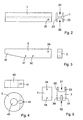
- Fig. 2 shows the antenna beam fitting 1 from the side and in profile.
- the fitting 1 is preferably devised having with an H-formed profile forming two elongated indentations 21, 22.
- the upper indentation 21 is intended to house the antenna beam 8.
- the lower indentation 22 is intended to house the mast head fitting 2, when the antenna is positioned in the folded, i.e. the horizontal position.
- the advantage having the mast head fitting 2 positioned in the indentation 22 is that the antenna bracket including the antenna gets a stable and safe construction, having large resistance against the speed wind and such, which would otherwise rotate and damage the construction.
- the antenna beam fitting is further provided with a bore 20 for a joint bolt (not shown).
- Fig. 3 shows the mast head fitting 2 from the side and in cross section.
- the fitting 2 has a rectangular cross section and can be designed within tapering in its end facing away from the joint 36.
- the fitting 2 is provided with a bore for the joint bolt described above, which also passes through the bores 20.
- Mounting holes 31, 32 are provided to attach to the mast or the mast head adjustment fitting 3.
- Fig. 4 shows the runner fitting 5, which is provided with a hole 43, through which hole the antenna mast 4, preferably of a circular cross section, can run. Further, the runner fitting 5 is provided with a notch 44 at its periphery to articulate towards the stay 6. Holes 41 are provided next to the notch 44 for a joint bolt (not shown).
- Fig. 5 shows the stay fitting 7 from the side and in cross section.
- the stay fitting 7 is provided with two notches, 51, 52; an upper notch 51 adapted to be attached to the antenna beam 8 by means of a bolt (not shown) through the holes 53 and through the antenna beam 8, and a low notch 52, which is intended to jointly attach the stay fitting 7 to the end close to the antenna beam of the stay 6.
- the antenna bracket is provided with spring means, mounted to divide the antenna beam fitting and the mast head fitting in the initial phase of an unfolding from the horizontal position.
- Said spring means can for example be a pressure spring, positioned between said fittings or a coil spring, positioned around the joint bolt in the joint 10 with a first spring arm bearing against the antenna beam fitting 1 and a second spring arm bearing against the mast head fitting 2.
- the running part corresponding to the part 5 has been mounted in a rail (not shown) on the antenna beam, while the fixed part of the stay is mounted at the mast, preferably close to the roof entrance 14.
Landscapes
- Engineering & Computer Science (AREA)
- Remote Sensing (AREA)
- Support Of Aerials (AREA)
- Details Of Aerials (AREA)
Claims (5)
- Dispositif d'antenne, pouvant convenir à un toit de véhicule, ledit dispositif comprenant une antenne (8), un mât (4) pour ladite antenne, et une entrée de toit (14) pour ledit mât, le dispositif étant conçu pour faire en sorte que l'antenne soit mise dans une position verticale lorsque le mât (4) est relevé, et dans une position horizontale lorsque le mât est abaissé, ledit dispositif comprenant un joint articulé (10) entre l'antenne (8) et la tête de mât (3), une garniture coulissante (5) pouvant se déplacer le long du mât et un étançon (6) relié à la garniture coulissante (5) et à l'antenne (8) par le biais d'une garniture d'étançon (7), caractérisé en ce qu'une garniture de faisceau d'antenne (1) comprenant le joint articulé (10) est montée sur l'antenne (8) de manière que le centre de gravité (12) de l'antenne est positionné sur un côté de la garniture d'étançon (7) de l'antenne par rapport au joint d'articulation (10) de sorte que, lorsque le mât est relevé, l'antenne est tournée par rapport à une position verticale et, lorsque le mât est abaissé, la garniture coulissante (5), contrainte par l'entrée de toit, via l'étançon (6) force la partie inférieure de l'antenne vers le haut, forçant ainsi l'antenne à pivoter autour du joint articulé (10) vers une position sensiblement horizontale.
- Dispositif d'antenne selon la revendication 1, comprenant également une garniture de tête de mât (2) fixée sur la tête du mât, dispositif dans lequel le joint articulé (10) est disposé entre le faisceau d'antenne et les garnitures de tête de mât (1,2) et dans lequel la garniture de faisceau d'antenne (1) présente une section transversale en forme de H, comprenant un renfoncement allongé supérieur (21) et inférieur (22) et en ce que la garniture de tête de mât (2) est conçue avec un profil sensiblement rectangulaire, dans lequel lesdites garnitures (1,2) sont adaptées de telle sorte que le renfoncement allongé inférieur de la garniture de faisceau d'antenne (1) et la garniture de tête de mât s'emboîtent l'un dans l'autre de façon ajustée.
- Dispositif d'antenne selon la revendication 2, dans lequel ledit renfoncement allongé supérieur (21) est conçu de telle sorte qu'un faisceau d'antenne peut y être ajusté.
- Dispositif d'antenne selon la revendication 3, comprenant de plus un rail fixé sur l'antenne (8) et dans lequel l'extrémité, proche de l'antenne, de l'étançon (6) se déplace dans ledit rail.
- Dispositif d'antenne selon l'une des revendications 2-4, comprenant de plus un dispositif à ressort, disposé pour assister une division de la garniture de faisceau d'antenne (1) et de la garniture de tête de mât (2) lorsque le mât est relevé.
Applications Claiming Priority (2)
| Application Number | Priority Date | Filing Date | Title |
|---|---|---|---|
| SE0400927A SE525638C2 (sv) | 2004-04-08 | 2004-04-08 | Antennfäste |
| SE4009270 | 2004-04-08 |
Publications (3)
| Publication Number | Publication Date |
|---|---|
| EP1585186A2 EP1585186A2 (fr) | 2005-10-12 |
| EP1585186A3 EP1585186A3 (fr) | 2005-10-26 |
| EP1585186B1 true EP1585186B1 (fr) | 2007-10-10 |
Family
ID=32173701
Family Applications (1)
| Application Number | Title | Priority Date | Filing Date |
|---|---|---|---|
| EP05102745A Expired - Lifetime EP1585186B1 (fr) | 2004-04-08 | 2005-04-07 | Support d'antenne pivotant |
Country Status (4)
| Country | Link |
|---|---|
| EP (1) | EP1585186B1 (fr) |
| AT (1) | ATE375606T1 (fr) |
| DE (1) | DE602005002775D1 (fr) |
| SE (1) | SE525638C2 (fr) |
Families Citing this family (1)
| Publication number | Priority date | Publication date | Assignee | Title |
|---|---|---|---|---|
| CN105098313B (zh) * | 2015-08-25 | 2017-09-01 | 长安大学 | 一种隧道地质超前预报雷达天线自适应调位装置 |
Family Cites Families (4)
| Publication number | Priority date | Publication date | Assignee | Title |
|---|---|---|---|---|
| DE3715024A1 (de) * | 1987-05-06 | 1988-11-17 | Kathrein Werke Kg | Einstellvorrichtung fuer eine antenne |
| WO1996013075A1 (fr) * | 1994-10-24 | 1996-05-02 | Maxview Limited | Perfectionnements se rapportant a des supports d'antenne |
| DE29519752U1 (de) * | 1995-09-04 | 1996-02-22 | Media Tech Vertriebs GmbH, 78647 Trossingen | Antennenvorrichtung |
| FI108365B (fi) * | 1999-02-11 | 2002-01-15 | Patria Vehicles Oy | Teleskooppimastojõrjestelmõ |
-
2004
- 2004-04-08 SE SE0400927A patent/SE525638C2/sv unknown
-
2005
- 2005-04-07 EP EP05102745A patent/EP1585186B1/fr not_active Expired - Lifetime
- 2005-04-07 DE DE602005002775T patent/DE602005002775D1/de not_active Expired - Lifetime
- 2005-04-07 AT AT05102745T patent/ATE375606T1/de not_active IP Right Cessation
Also Published As
| Publication number | Publication date |
|---|---|
| SE0400927L (sv) | 2005-03-22 |
| SE0400927D0 (sv) | 2004-04-08 |
| DE602005002775D1 (de) | 2007-11-22 |
| SE525638C2 (sv) | 2005-03-22 |
| EP1585186A2 (fr) | 2005-10-12 |
| ATE375606T1 (de) | 2007-10-15 |
| EP1585186A3 (fr) | 2005-10-26 |
Similar Documents
| Publication | Publication Date | Title |
|---|---|---|
| KR102489855B1 (ko) | 기지국 안테나용 클램핑 장치 | |
| US20030175101A1 (en) | Ladder rack assembly | |
| EP1028482A2 (fr) | Système de mât téléscopique | |
| CA2447379A1 (fr) | Coulisseau et support de cable de sauvetage | |
| US6591556B2 (en) | Self-centering pivotal canopy | |
| US20220393333A1 (en) | Antenna mounting device and antenna system for antenna assembly | |
| US10690327B2 (en) | Folding light tower | |
| KR20200115088A (ko) | 기지국용 안테나 지지장치 | |
| EP2961639B1 (fr) | Galerie utilitaire descendante pour véhicules | |
| CA2881002A1 (fr) | Stabilisation du couple d'un mat d'appareil de levage | |
| KR20200024091A (ko) | 안테나 설치 구조물 | |
| WO2006020863A3 (fr) | Système d'antenne satellite stockable nomade | |
| EP1585186A2 (fr) | Support d'antenne pivotant | |
| US9827895B2 (en) | Mechanical arrangement and a method for a trailer | |
| KR102818243B1 (ko) | 루프탑 텐트 | |
| EP0296957A2 (fr) | Mât télescopique auto-élévateur | |
| KR102122177B1 (ko) | 기지국용 안테나 지지장치 | |
| US6017018A (en) | Lift-a-top plus | |
| EP2634507A1 (fr) | Ensemble de structure de support et panneau solaire et procédé pour disposer un panneau solaire sur une surface | |
| FR2719070A1 (fr) | Mât télescopique. | |
| KR102169719B1 (ko) | 기지국용 안테나 지지장치 | |
| AU2011100415B9 (en) | Awning and frame assembly therefor | |
| KR101955609B1 (ko) | 고소작업차의 버켓 레스트 | |
| US2963125A (en) | Antenna mounting structure | |
| US12139925B2 (en) | Portable shade device |
Legal Events
| Date | Code | Title | Description |
|---|---|---|---|
| PUAI | Public reference made under article 153(3) epc to a published international application that has entered the european phase |
Free format text: ORIGINAL CODE: 0009012 |
|
| PUAL | Search report despatched |
Free format text: ORIGINAL CODE: 0009013 |
|
| AK | Designated contracting states |
Kind code of ref document: A2 Designated state(s): AT BE BG CH CY CZ DE DK EE ES FI FR GB GR HU IE IS IT LI LT LU MC NL PL PT RO SE SI SK TR |
|
| AX | Request for extension of the european patent |
Extension state: AL BA HR LV MK YU |
|
| AK | Designated contracting states |
Kind code of ref document: A3 Designated state(s): AT BE BG CH CY CZ DE DK EE ES FI FR GB GR HU IE IS IT LI LT LU MC NL PL PT RO SE SI SK TR |
|
| AX | Request for extension of the european patent |
Extension state: AL BA HR LV MK YU |
|
| 17P | Request for examination filed |
Effective date: 20060328 |
|
| AKX | Designation fees paid |
Designated state(s): AT BE BG CH CY CZ DE DK EE ES FI FR GB GR HU IE IS IT LI LT LU MC NL PL PT RO SE SI SK TR |
|
| 17Q | First examination report despatched |
Effective date: 20060524 |
|
| GRAP | Despatch of communication of intention to grant a patent |
Free format text: ORIGINAL CODE: EPIDOSNIGR1 |
|
| RIN1 | Information on inventor provided before grant (corrected) |
Inventor name: MARTENSSON, BENGT Inventor name: GUSTAFSSON, JAN |
|
| GRAS | Grant fee paid |
Free format text: ORIGINAL CODE: EPIDOSNIGR3 |
|
| GRAL | Information related to payment of fee for publishing/printing deleted |
Free format text: ORIGINAL CODE: EPIDOSDIGR3 |
|
| GRAS | Grant fee paid |
Free format text: ORIGINAL CODE: EPIDOSNIGR3 |
|
| GRAA | (expected) grant |
Free format text: ORIGINAL CODE: 0009210 |
|
| AK | Designated contracting states |
Kind code of ref document: B1 Designated state(s): AT BE BG CH CY CZ DE DK EE ES FI FR GB GR HU IE IS IT LI LT LU MC NL PL PT RO SE SI SK TR |
|
| REG | Reference to a national code |
Ref country code: GB Ref legal event code: FG4D |
|
| REG | Reference to a national code |
Ref country code: CH Ref legal event code: EP |
|
| REG | Reference to a national code |
Ref country code: IE Ref legal event code: FG4D |
|
| REF | Corresponds to: |
Ref document number: 602005002775 Country of ref document: DE Date of ref document: 20071122 Kind code of ref document: P |
|
| NLV1 | Nl: lapsed or annulled due to failure to fulfill the requirements of art. 29p and 29m of the patents act | ||
| PG25 | Lapsed in a contracting state [announced via postgrant information from national office to epo] |
Ref country code: SE Free format text: LAPSE BECAUSE OF FAILURE TO SUBMIT A TRANSLATION OF THE DESCRIPTION OR TO PAY THE FEE WITHIN THE PRESCRIBED TIME-LIMIT Effective date: 20080110 Ref country code: NL Free format text: LAPSE BECAUSE OF FAILURE TO SUBMIT A TRANSLATION OF THE DESCRIPTION OR TO PAY THE FEE WITHIN THE PRESCRIBED TIME-LIMIT Effective date: 20071010 Ref country code: LI Free format text: LAPSE BECAUSE OF FAILURE TO SUBMIT A TRANSLATION OF THE DESCRIPTION OR TO PAY THE FEE WITHIN THE PRESCRIBED TIME-LIMIT Effective date: 20071010 Ref country code: ES Free format text: LAPSE BECAUSE OF FAILURE TO SUBMIT A TRANSLATION OF THE DESCRIPTION OR TO PAY THE FEE WITHIN THE PRESCRIBED TIME-LIMIT Effective date: 20080121 Ref country code: CH Free format text: LAPSE BECAUSE OF FAILURE TO SUBMIT A TRANSLATION OF THE DESCRIPTION OR TO PAY THE FEE WITHIN THE PRESCRIBED TIME-LIMIT Effective date: 20071010 |
|
| REG | Reference to a national code |
Ref country code: CH Ref legal event code: PL |
|
| PG25 | Lapsed in a contracting state [announced via postgrant information from national office to epo] |
Ref country code: LT Free format text: LAPSE BECAUSE OF FAILURE TO SUBMIT A TRANSLATION OF THE DESCRIPTION OR TO PAY THE FEE WITHIN THE PRESCRIBED TIME-LIMIT Effective date: 20071010 Ref country code: PL Free format text: LAPSE BECAUSE OF FAILURE TO SUBMIT A TRANSLATION OF THE DESCRIPTION OR TO PAY THE FEE WITHIN THE PRESCRIBED TIME-LIMIT Effective date: 20071010 Ref country code: PT Free format text: LAPSE BECAUSE OF FAILURE TO SUBMIT A TRANSLATION OF THE DESCRIPTION OR TO PAY THE FEE WITHIN THE PRESCRIBED TIME-LIMIT Effective date: 20080310 Ref country code: BG Free format text: LAPSE BECAUSE OF FAILURE TO SUBMIT A TRANSLATION OF THE DESCRIPTION OR TO PAY THE FEE WITHIN THE PRESCRIBED TIME-LIMIT Effective date: 20080110 Ref country code: IS Free format text: LAPSE BECAUSE OF FAILURE TO SUBMIT A TRANSLATION OF THE DESCRIPTION OR TO PAY THE FEE WITHIN THE PRESCRIBED TIME-LIMIT Effective date: 20080210 |
|
| PG25 | Lapsed in a contracting state [announced via postgrant information from national office to epo] |
Ref country code: AT Free format text: LAPSE BECAUSE OF FAILURE TO SUBMIT A TRANSLATION OF THE DESCRIPTION OR TO PAY THE FEE WITHIN THE PRESCRIBED TIME-LIMIT Effective date: 20071010 |
|
| EN | Fr: translation not filed | ||
| PG25 | Lapsed in a contracting state [announced via postgrant information from national office to epo] |
Ref country code: DK Free format text: LAPSE BECAUSE OF FAILURE TO SUBMIT A TRANSLATION OF THE DESCRIPTION OR TO PAY THE FEE WITHIN THE PRESCRIBED TIME-LIMIT Effective date: 20071010 Ref country code: CZ Free format text: LAPSE BECAUSE OF FAILURE TO SUBMIT A TRANSLATION OF THE DESCRIPTION OR TO PAY THE FEE WITHIN THE PRESCRIBED TIME-LIMIT Effective date: 20071010 |
|
| PLBE | No opposition filed within time limit |
Free format text: ORIGINAL CODE: 0009261 |
|
| STAA | Information on the status of an ep patent application or granted ep patent |
Free format text: STATUS: NO OPPOSITION FILED WITHIN TIME LIMIT |
|
| PG25 | Lapsed in a contracting state [announced via postgrant information from national office to epo] |
Ref country code: SK Free format text: LAPSE BECAUSE OF FAILURE TO SUBMIT A TRANSLATION OF THE DESCRIPTION OR TO PAY THE FEE WITHIN THE PRESCRIBED TIME-LIMIT Effective date: 20071010 Ref country code: RO Free format text: LAPSE BECAUSE OF FAILURE TO SUBMIT A TRANSLATION OF THE DESCRIPTION OR TO PAY THE FEE WITHIN THE PRESCRIBED TIME-LIMIT Effective date: 20071010 Ref country code: BE Free format text: LAPSE BECAUSE OF FAILURE TO SUBMIT A TRANSLATION OF THE DESCRIPTION OR TO PAY THE FEE WITHIN THE PRESCRIBED TIME-LIMIT Effective date: 20071010 |
|
| 26N | No opposition filed |
Effective date: 20080711 |
|
| PG25 | Lapsed in a contracting state [announced via postgrant information from national office to epo] |
Ref country code: FR Free format text: LAPSE BECAUSE OF FAILURE TO SUBMIT A TRANSLATION OF THE DESCRIPTION OR TO PAY THE FEE WITHIN THE PRESCRIBED TIME-LIMIT Effective date: 20080725 Ref country code: DE Free format text: LAPSE BECAUSE OF FAILURE TO SUBMIT A TRANSLATION OF THE DESCRIPTION OR TO PAY THE FEE WITHIN THE PRESCRIBED TIME-LIMIT Effective date: 20080111 |
|
| PG25 | Lapsed in a contracting state [announced via postgrant information from national office to epo] |
Ref country code: MC Free format text: LAPSE BECAUSE OF NON-PAYMENT OF DUE FEES Effective date: 20080430 |
|
| PG25 | Lapsed in a contracting state [announced via postgrant information from national office to epo] |
Ref country code: EE Free format text: LAPSE BECAUSE OF FAILURE TO SUBMIT A TRANSLATION OF THE DESCRIPTION OR TO PAY THE FEE WITHIN THE PRESCRIBED TIME-LIMIT Effective date: 20071010 Ref country code: GR Free format text: LAPSE BECAUSE OF FAILURE TO SUBMIT A TRANSLATION OF THE DESCRIPTION OR TO PAY THE FEE WITHIN THE PRESCRIBED TIME-LIMIT Effective date: 20080111 |
|
| PG25 | Lapsed in a contracting state [announced via postgrant information from national office to epo] |
Ref country code: FI Free format text: LAPSE BECAUSE OF FAILURE TO SUBMIT A TRANSLATION OF THE DESCRIPTION OR TO PAY THE FEE WITHIN THE PRESCRIBED TIME-LIMIT Effective date: 20071010 |
|
| PG25 | Lapsed in a contracting state [announced via postgrant information from national office to epo] |
Ref country code: IE Free format text: LAPSE BECAUSE OF NON-PAYMENT OF DUE FEES Effective date: 20080407 |
|
| PG25 | Lapsed in a contracting state [announced via postgrant information from national office to epo] |
Ref country code: SI Free format text: LAPSE BECAUSE OF FAILURE TO SUBMIT A TRANSLATION OF THE DESCRIPTION OR TO PAY THE FEE WITHIN THE PRESCRIBED TIME-LIMIT Effective date: 20071010 |
|
| PG25 | Lapsed in a contracting state [announced via postgrant information from national office to epo] |
Ref country code: CY Free format text: LAPSE BECAUSE OF FAILURE TO SUBMIT A TRANSLATION OF THE DESCRIPTION OR TO PAY THE FEE WITHIN THE PRESCRIBED TIME-LIMIT Effective date: 20071010 |
|
| PGFP | Annual fee paid to national office [announced via postgrant information from national office to epo] |
Ref country code: GB Payment date: 20090429 Year of fee payment: 5 |
|
| PG25 | Lapsed in a contracting state [announced via postgrant information from national office to epo] |
Ref country code: LU Free format text: LAPSE BECAUSE OF NON-PAYMENT OF DUE FEES Effective date: 20080407 Ref country code: HU Free format text: LAPSE BECAUSE OF FAILURE TO SUBMIT A TRANSLATION OF THE DESCRIPTION OR TO PAY THE FEE WITHIN THE PRESCRIBED TIME-LIMIT Effective date: 20080411 |
|
| PG25 | Lapsed in a contracting state [announced via postgrant information from national office to epo] |
Ref country code: TR Free format text: LAPSE BECAUSE OF FAILURE TO SUBMIT A TRANSLATION OF THE DESCRIPTION OR TO PAY THE FEE WITHIN THE PRESCRIBED TIME-LIMIT Effective date: 20071010 |
|
| GBPC | Gb: european patent ceased through non-payment of renewal fee |
Effective date: 20100407 |
|
| PG25 | Lapsed in a contracting state [announced via postgrant information from national office to epo] |
Ref country code: IT Free format text: LAPSE BECAUSE OF NON-PAYMENT OF DUE FEES Effective date: 20080430 |
|
| PG25 | Lapsed in a contracting state [announced via postgrant information from national office to epo] |
Ref country code: GB Free format text: LAPSE BECAUSE OF NON-PAYMENT OF DUE FEES Effective date: 20100407 |