EP1584890A2 - Tête militaire génératrice d'éclats - Google Patents
Tête militaire génératrice d'éclats Download PDFInfo
- Publication number
- EP1584890A2 EP1584890A2 EP05290633A EP05290633A EP1584890A2 EP 1584890 A2 EP1584890 A2 EP 1584890A2 EP 05290633 A EP05290633 A EP 05290633A EP 05290633 A EP05290633 A EP 05290633A EP 1584890 A2 EP1584890 A2 EP 1584890A2
- Authority
- EP
- European Patent Office
- Prior art keywords
- relays
- military
- explosive charge
- military head
- disposed
- Prior art date
- Legal status (The legal status is an assumption and is not a legal conclusion. Google has not performed a legal analysis and makes no representation as to the accuracy of the status listed.)
- Granted
Links
- 239000012634 fragment Substances 0.000 title description 5
- 239000002360 explosive Substances 0.000 claims abstract description 26
- 230000037452 priming Effects 0.000 claims abstract description 18
- 238000005474 detonation Methods 0.000 claims abstract description 9
- 230000000977 initiatory effect Effects 0.000 claims abstract description 7
- 206010041662 Splinter Diseases 0.000 claims 1
- 239000003999 initiator Substances 0.000 description 4
- 230000035939 shock Effects 0.000 description 4
- 239000013598 vector Substances 0.000 description 4
- 235000015842 Hesperis Nutrition 0.000 description 3
- 235000012633 Iberis amara Nutrition 0.000 description 3
- 239000002131 composite material Substances 0.000 description 2
- 238000003754 machining Methods 0.000 description 2
- 239000000463 material Substances 0.000 description 2
- 239000000203 mixture Substances 0.000 description 2
- 239000011347 resin Substances 0.000 description 2
- 229920005989 resin Polymers 0.000 description 2
- 238000011282 treatment Methods 0.000 description 2
- 241001416181 Axis axis Species 0.000 description 1
- 239000004952 Polyamide Substances 0.000 description 1
- 229910000831 Steel Inorganic materials 0.000 description 1
- 238000004026 adhesive bonding Methods 0.000 description 1
- 239000000956 alloy Substances 0.000 description 1
- 229910045601 alloy Inorganic materials 0.000 description 1
- 230000005540 biological transmission Effects 0.000 description 1
- 230000015572 biosynthetic process Effects 0.000 description 1
- 239000004020 conductor Substances 0.000 description 1
- 238000001514 detection method Methods 0.000 description 1
- 238000010586 diagram Methods 0.000 description 1
- 238000005516 engineering process Methods 0.000 description 1
- 238000004519 manufacturing process Methods 0.000 description 1
- 239000004033 plastic Substances 0.000 description 1
- 229920002647 polyamide Polymers 0.000 description 1
- 230000002250 progressing effect Effects 0.000 description 1
- 239000010959 steel Substances 0.000 description 1
Images



Classifications
-
- F—MECHANICAL ENGINEERING; LIGHTING; HEATING; WEAPONS; BLASTING
- F42—AMMUNITION; BLASTING
- F42C—AMMUNITION FUZES; ARMING OR SAFETY MEANS THEREFOR
- F42C19/00—Details of fuzes
- F42C19/08—Primers; Detonators
- F42C19/095—Arrangements of a multiplicity of primers or detonators, dispersed around a warhead, one of the primers or detonators being selected for directional detonation effects
Definitions
- the technical field of the invention is that of the heads military generator of splinters.
- Patents FR2678723, US5544589 and the certificate of utility FR2388468 thus describe a military head in which explosive charges spread around a shrapnel envelope make it possible to ensure deformation of the localized envelope next to a target detected by a proximity rocket.
- certificate of utility FR2388468 proposes to ensure the initiation of the charge by a priming means disposed in a manner diametrically opposite to the deformed zone of the envelope.
- the invention relates to a military head chip generator comprising at least one load explosive disposed in an envelope, and a means of initiation, head characterized in that the priming means comprises at minus a ring of detonation relays regularly angularly distributed around the axis of the military head, relays arranged in the vicinity of the explosive charge and having their direction of action oriented substantially radially towards the axis of the head, the relays being otherwise in solidarity with an inert support.
- the military head can have two coaxial explosive charge units and same diameter, the relay ring being disposed between the two blocks.
- the military head may include a single explosive charge block, the relay ring being disposed at one end of the block.
- the shell-generating envelope may be constituted by two cylindrical parts arranged on both sides of the relay crown.
- the military head may be placed inside an ammunition case and have a diameter smaller than the inside diameter of the case.
- each relay can be sized from not to be able to initiate the loading on its own explosive, but this initiation is possible when at least two relays are initiated simultaneously.
- the relay ring can be connected to a device electronic ignition system, which is itself connected to a rocket proximity that can detect the position of a target by report to the military head, the priming device determining from the positioning of the target the relays which must be initiated to guide the splinters into direction of the target.
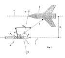
- FIG. 1 shows a munition 1, for example a missile, which passes close to a target 2 such a aircraft.
- the trajectory 3 of the ammunition (which is also the axis of the ammunition) is substantially parallel to trajectory 4 of the target and she is at a distance D of this last.
- the ammunition 1 comprises a proximity rocket 5 whose detection directions ( ⁇ 1, ⁇ 2 ... ⁇ i) are distributed according to a cone, coaxial with the axis 3 of the ammunition, and half-angle at the top ⁇ .
- Such proximity rockets are well known to the skilled person.
- the patents FR2388468 and FR2678723 describe exemplary embodiments of such rockets. These rockets are equipped with radar technology sensors or infra red.
- the rocket 5 makes it possible to determine the direction ⁇ i according to which is positioned the target 2 with respect to the ammunition.
- the ammunition 1 has a military head 6 which shrapnel.
- the vector V schematizes the speed of projection of the fragments in a reference linked to the ammunition.
- the vector VR is the velocity vector of the ammunition 1.
- the composition of these two velocity vectors leads to a projection of fragments in a direction A.
- the military head 6 is endowed priming means for focusing the chips in the direction of the target 2.
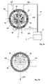
- Figures 2a and 2b show a first mode of production.
- the military head 6 is housed in a case 7 of the ammunition, the case may be metallic or made of a composite material.
- the head military 6 includes two blocks 17a, 17b of a cargo explosive. These two blocks are cylindrical and coaxial and they have axis axis 3 of the ammunition 1. They also the same diameter.
- Each block 17a, 17b is disposed in an envelope separate chip generator 8a, 8b which is closed to a end by a cover 12a, 12b.
- envelopes will be made of steel or dense alloy and they can include machining or embrittlement treatment particular favoring the formation of splinters. These machining or treatments are well known to those skilled in the art.
- the military head 6 is endowed a priming means which comprises at least one ring of detonation relay 9, regularly distributed angularly around axis 3 of the military head 6.
- the head 6 has six detonation relays 9a, 9b, 9c, 9d, 9e and 9f (see Figure 2b). These relays are arranged in the vicinity of the explosive charge blocks 17a and 17b and they each have their direction of action (d a , d b , d c , d d , d e , d f ) which is oriented substantially radially towards the axis 3 of the military head 6. These directions of action are shown in Figure 3a.
- the relay ring 9 is arranged between the two blocks explosives 17a and 17b and the relays 9 are all solidary of an inert support 10 which is interposed between the two blocks explosive charge 17a and 17b.
- the support 10 is shown uncut and the visible relays are relays 9f, 9e and 9d.
- the support 10 will be formed for example by a block of polyamide or by another type of plastic material or composite.
- All relays 9 are connected by wires (no shown in these figures) to a priming device 11 itself connected to the proximity rocket. son can be positioned for example in grooves longitudinal of the case 7.
- the rocket 5 can detect the position of the target 2 compared to the military head 6. From this positioning of the target, the priming device determines the relays 9 that must be initiated to guide the shards towards the target 2.
- Primer and rocket can of course be consisting of a single subset of the munition 1.
- Figures 3a and 3b show the mode ignition coil relay 9. All relays are connected to the ignition device 11 by conductors 13a, 13b, 13c, 13d, 13e and 13f. Drivers can be grouped into a cable 13. It will also be possible to simplify the wiring implement a two-wire BUS type link of data transmission which will connect in parallel all 9. In this case, the relays must have a logical electronic circuit allowing them to dialogue with the priming device 11 and to recognize the orders transmitted.
- Patent FR2801698 describes such a device for logic control of pyrotechnic components.
- each relay 9 will be dimensioned so to not be able to initiate by itself the explosive charge 17. However, this initiation must be possible when at least two neighboring relays are initiated simultaneously. It is easy for the skilled person to define relays of such so that the energy provided by the composition of the waves of detonation from two relays is sufficient to prime the blocks explosives 17a, 17b while the energy of a single relay is insufficient.
- FIG. 3b shows the progression in the support 10 of the shock waves 14a and 14f coming from the two relays 9a and 9f, initiated simultaneously by the priming device 11. It can be seen that these waves are composed and that a wave results therefrom oriented along the plane of the bisector ⁇ a, f individual directions of action d f and d a .
- shock wave from the priming means six different directions of action regularly distributed angularly around the axis 3 of the military head.
- relays 9 are not oriented towards explosive blocks to initiate 17a and 17b.
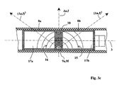
- the shock wave that is generated by each relay 9 has a spherical symmetry. It therefore progresses not only along the direction ⁇ a, f but also laterally in each of the blocks 17a, 17b.
- FIG. 3c shows this progression of the shock waves 15 and 16 which develop from the support 10 towards the ends of the blocks 17a and 17b in the symmetrical directions ( ⁇ a, f ) 1 and ( ⁇ a, f ) 2 from each other with respect to the radial direction ⁇ a, f .
- the kinetic energy is then maximal for splinters generated by the envelope generators 8a, 8b which are arranged opposite the target. It is minimal for splinters generated by neighboring envelope generators relays initiated (9a, 9f), so for the generators that are oriented in a direction opposite to that of the target.
- the invention allows, with a montage extremely simple means of priming, to achieve a military head that can direct the fragments according to several privileged directions, the management being chosen in according to the indications given by a proximity rocket.
- a simultaneous initiation of six relays can generate in each block of explosive 17a, 17b a detonation wave progressing along the axis 3 of the military head and this in a way equivalent to what would be obtained with a single relay arranged axially at a ends of the block.
- the military head according to the invention can therefore also work with a generation mode splinters following an unfocused sheaf.
- Figures 4a and 4b show another way of making a military head 6 in which a crown detonation relay 9 is disposed on one side of a block unique 17 explosive material.
- the relay ring 9 is arranged in a support inert 10 that is applied against the loading block explosive 17.
- the block is shown uncut and the visible relays are the Relay 9f, 9e and 9d.
- the mode of operation is similar to that described above with reference to FIGS. 2a to 3c.
- This embodiment makes it possible to project the chips for example in the direction ( ⁇ d, c ) 1 .
- This military head is easy to implement and integrate into an ammunition.
- FIG. 5 shows a variant military head embodiment of the invention. This variant differs from previous in that the military head 6 is sub-calibrated relative to the inside diameter of the case 7.
- the head represented here has a structure similar to that Figures 2a and 2b and therefore includes two explosive blocks 17a, 17b separated by a relay ring 9 disposed in an inert support 10.
- the two blocks 17a, 17b and the support 10 are linked to each other by gluing.
- the whole is united by elsewhere of the two end covers 12a and 12b which are to the inside diameter of the case 7 and which ensure the radial positioning of the head relative to the case 7.
- the annular space separating the inner surface of the case 7 and the military head 6 has a thickness of a few millimeters. Such a provision makes it possible to pass easily the different wires 13 connecting the relays 9 to priming device 11.
Landscapes
- Engineering & Computer Science (AREA)
- General Engineering & Computer Science (AREA)
- Aiming, Guidance, Guns With A Light Source, Armor, Camouflage, And Targets (AREA)
- Portable Nailing Machines And Staplers (AREA)
- Radar Systems Or Details Thereof (AREA)
- Other Liquid Machine Or Engine Such As Wave Power Use (AREA)
- Professional, Industrial, Or Sporting Protective Garments (AREA)
- Orthopedics, Nursing, And Contraception (AREA)
- Particle Accelerators (AREA)
Abstract
Description
- la figure 1 est un schéma simplifié montrant l'attaque d'une cible par une munition incorporant une tête militaire selon l'invention,
- les figures 2a et 2b sont deux vues d'un premier mode de réalisation d'une tête militaire selon l'invention, la vue 2a étant une coupe longitudinale partielle et la vue 2b une coupe transversale réalisée suivant le plan dont la trace AA est repérée à la figure 2a,
- la figure 3a est une vue en coupe schématisant le raccordement des relais de détonation et du dispositif d'amorçage électronique,
- les figures 3b et 3c montrent le fonctionnement du dispositif d'amorçage,
- les figures 4a et 4b sont deux vues d'un deuxième mode de réalisation d'une tête militaire selon l'invention, la vue 4a étant une coupe longitudinale partielle et la vue 4b une coupe transversale réalisée suivant le plan dont la trace BB est repérée à la figure 4a,
- la figure 5 est une vue en coupe longitudinale d'une variante de réalisation d'une tête militaire selon l'invention.
Claims (7)
- Tête militaire (6) génératrice d'éclats comprenant au moins un chargement explosif (17) disposé dans une enveloppe (8), et un moyen d'amorçage, tête caractérisée en ce que le moyen d'amorçage comporte au moins une couronne de relais de détonation (9) régulièrement répartis angulairement autour de l'axe (3) de la tête militaire, relais disposés au voisinage du chargement explosif et ayant leur direction d'action (da...df) orientée sensiblement radialement vers l'axe (3) de la tête, les relais (9) étant par ailleurs solidaires d'un support inerte (10).
- Tête militaire selon la revendication 1, caractérisée en ce qu'elle comporte deux blocs (17a,17b) de chargement explosif, blocs coaxiaux et de même diamètre, la couronne de relais (9) étant disposée entre les deux blocs.
- Tête militaire selon la revendication 1, caractérisée en ce qu'elle comporte un seul bloc (17) de chargement explosif, la couronne de relais (9) étant disposée au niveau d'une extrémité du bloc.
- Tête militaire selon la revendication 2, caractérisée en ce que l'enveloppe génératrice d'éclats est constituée par deux parties cylindriques (8a,8b) disposées de part et d'autre de la couronne de relais (9).
- Tête militaire selon une des revendications 1 à 4, caractérisée en ce qu'elle est disposée à l'intérieur d'un étui (7) de munition, et en ce qu'elle a un diamètre inférieur au diamètre interne de l'étui.
- Tête militaire selon une des revendications 1 à 5, caractérisée en ce que chaque relais (9) est dimensionné de façon à ne pas pouvoir initier à lui seul le chargement explosif (17), cette initiation étant cependant possible lorsque au moins deux relais sont initiés simultanément.
- Tête militaire selon une des revendications 1 à 6, caractérisée en ce que la couronne de relais (9) est reliée à un dispositif d'amorçage électronique (11), lui-même relié à une fusée de proximité (5) pouvant détecter la position d'une cible (2) par rapport à la tête militaire (6), le dispositif d'amorçage déterminant à partir du positionnement de la cible les relais qui doivent être initiés pour orienter les éclats en direction de la cible (2).
Applications Claiming Priority (2)
| Application Number | Priority Date | Filing Date | Title |
|---|---|---|---|
| FR0403728A FR2868832B1 (fr) | 2004-04-07 | 2004-04-07 | Tete militaire generatrice d'eclats |
| FR0403728 | 2004-04-07 |
Publications (3)
| Publication Number | Publication Date |
|---|---|
| EP1584890A2 true EP1584890A2 (fr) | 2005-10-12 |
| EP1584890A3 EP1584890A3 (fr) | 2006-06-21 |
| EP1584890B1 EP1584890B1 (fr) | 2011-08-17 |
Family
ID=34896729
Family Applications (1)
| Application Number | Title | Priority Date | Filing Date |
|---|---|---|---|
| EP05290633A Expired - Lifetime EP1584890B1 (fr) | 2004-04-07 | 2005-03-23 | Tête militaire génératrice d'éclats |
Country Status (4)
| Country | Link |
|---|---|
| EP (1) | EP1584890B1 (fr) |
| AT (1) | ATE520955T1 (fr) |
| ES (1) | ES2369668T3 (fr) |
| FR (1) | FR2868832B1 (fr) |
Cited By (2)
| Publication number | Priority date | Publication date | Assignee | Title |
|---|---|---|---|---|
| FR2940683A1 (fr) * | 2008-12-31 | 2010-07-02 | Nexter Munitions | Tete militaire projetant des barreaux. |
| FR3041745A1 (fr) * | 2015-09-28 | 2017-03-31 | Nexter Munitions | Enveloppe de tete militaire et tete militaire incorporant une telle enveloppe |
Citations (7)
| Publication number | Priority date | Publication date | Assignee | Title |
|---|---|---|---|---|
| US3877376A (en) | 1960-07-27 | 1975-04-15 | Us Navy | Directed warhead |
| US4026213A (en) | 1971-06-17 | 1977-05-31 | The United States Of America As Represented By The Secretary Of The Navy | Selectively aimable warhead |
| FR2388468A7 (fr) | 1975-01-30 | 1978-11-17 | France Etat | Projectile explosif, notamment de defense anti-aerienne |
| FR2678723A1 (fr) | 1981-06-26 | 1993-01-08 | France Etat | Projectile explosif, notamment anti-aerien, comprenant une charge a effet directionnel rotatif. |
| US5182418A (en) | 1965-06-21 | 1993-01-26 | The United States Of America As Represented By The Secretary Of The Navy | Aimable warhead |
| US5544589A (en) | 1991-09-06 | 1996-08-13 | Daimler-Benz Aerospace Ag | Fragmentation warhead |
| FR2839778A1 (fr) | 2002-05-18 | 2003-11-21 | Tdw Ges Fur Verteidigungstechn | Tete d'obus |
Family Cites Families (1)
| Publication number | Priority date | Publication date | Assignee | Title |
|---|---|---|---|---|
| DE1453815A1 (de) * | 1965-12-10 | 1969-02-06 | Boelkow Gmbh | Verfahren zum Ausloesen der Sprengladung bei einem Sprengladungsgeschoss |
-
2004
- 2004-04-07 FR FR0403728A patent/FR2868832B1/fr not_active Expired - Fee Related
-
2005
- 2005-03-23 ES ES05290633T patent/ES2369668T3/es not_active Expired - Lifetime
- 2005-03-23 AT AT05290633T patent/ATE520955T1/de not_active IP Right Cessation
- 2005-03-23 EP EP05290633A patent/EP1584890B1/fr not_active Expired - Lifetime
Patent Citations (7)
| Publication number | Priority date | Publication date | Assignee | Title |
|---|---|---|---|---|
| US3877376A (en) | 1960-07-27 | 1975-04-15 | Us Navy | Directed warhead |
| US5182418A (en) | 1965-06-21 | 1993-01-26 | The United States Of America As Represented By The Secretary Of The Navy | Aimable warhead |
| US4026213A (en) | 1971-06-17 | 1977-05-31 | The United States Of America As Represented By The Secretary Of The Navy | Selectively aimable warhead |
| FR2388468A7 (fr) | 1975-01-30 | 1978-11-17 | France Etat | Projectile explosif, notamment de defense anti-aerienne |
| FR2678723A1 (fr) | 1981-06-26 | 1993-01-08 | France Etat | Projectile explosif, notamment anti-aerien, comprenant une charge a effet directionnel rotatif. |
| US5544589A (en) | 1991-09-06 | 1996-08-13 | Daimler-Benz Aerospace Ag | Fragmentation warhead |
| FR2839778A1 (fr) | 2002-05-18 | 2003-11-21 | Tdw Ges Fur Verteidigungstechn | Tete d'obus |
Cited By (3)
| Publication number | Priority date | Publication date | Assignee | Title |
|---|---|---|---|---|
| FR2940683A1 (fr) * | 2008-12-31 | 2010-07-02 | Nexter Munitions | Tete militaire projetant des barreaux. |
| EP2204634A1 (fr) * | 2008-12-31 | 2010-07-07 | Nexter Munitions | Tête militaire projetant des barreaux |
| FR3041745A1 (fr) * | 2015-09-28 | 2017-03-31 | Nexter Munitions | Enveloppe de tete militaire et tete militaire incorporant une telle enveloppe |
Also Published As
| Publication number | Publication date |
|---|---|
| FR2868832A1 (fr) | 2005-10-14 |
| ATE520955T1 (de) | 2011-09-15 |
| EP1584890B1 (fr) | 2011-08-17 |
| ES2369668T3 (es) | 2011-12-02 |
| FR2868832B1 (fr) | 2008-07-11 |
| EP1584890A3 (fr) | 2006-06-21 |
Similar Documents
| Publication | Publication Date | Title |
|---|---|---|
| EP1176385B1 (fr) | Munition explosive à corps fragmentable | |
| EP0221218B1 (fr) | Tête militaire à charges formées montées en tandem | |
| CA2221580C (fr) | Charge generatrice de noyau a performances ameliorees | |
| EP0561085B1 (fr) | Procédé utilisant un dispositif explosif à charge creuse pour perforer un blindage protégé par un préblindage actif | |
| EP1584890B1 (fr) | Tête militaire génératrice d'éclats | |
| FR2771497A1 (fr) | Projectile explosif | |
| FR2646503A1 (fr) | Dispositif d'ejection de conteneurs sur trajectoire | |
| FR2520102A1 (fr) | Charge creuse, notamment pour missile | |
| EP0752572B1 (fr) | Tête militaire à charge formée et munition équipée d'une telle tête militaire | |
| EP1672308B1 (fr) | Disposition d'initiation pour charge explosive ou composition pyrotechnique | |
| FR2683034A1 (fr) | Tete de combat. | |
| FR2475716A2 (fr) | Mine dispersable bidirectionnelle a charge formee | |
| EP2327952A1 (fr) | Tête militaire à charges en tandem | |
| FR2552871A1 (fr) | Projectile antichar agissant en vitesse defilante | |
| FR2993355A1 (fr) | Munition a rayon de letalite reduit et procede de fabrication d'une telle munition | |
| EP1302741B1 (fr) | Munition explosive | |
| FR2738061A1 (fr) | Tete de combat | |
| EP1577635B1 (fr) | Dispositif d'initiation de deux charges explosives et tête militaire mettant en oeuvre un tel dispositif d'initiation | |
| FR2992408A1 (fr) | Tete militaire a projection de noyaux | |
| EP2204634A1 (fr) | Tête militaire projetant des barreaux | |
| EP0401075A1 (fr) | Dispositif explosif à éclats préfragmentés et procédé de réalisation d'un tel dispositif | |
| FR2894331A1 (fr) | Projectile perforant et procede de fabrication d'un tel projectile | |
| FR2577037A1 (fr) | Tete militaire a charges formees montees en tandem | |
| FR2652892A1 (fr) | Tete militaire avec effet d'eclat renforce. | |
| EP1870640B1 (fr) | Tête militaire engendrant un noyau tubulaire |
Legal Events
| Date | Code | Title | Description |
|---|---|---|---|
| PUAI | Public reference made under article 153(3) epc to a published international application that has entered the european phase |
Free format text: ORIGINAL CODE: 0009012 |
|
| AK | Designated contracting states |
Kind code of ref document: A2 Designated state(s): AT BE BG CH CY CZ DE DK EE ES FI FR GB GR HU IE IS IT LI LT LU MC NL PL PT RO SE SI SK TR |
|
| AX | Request for extension of the european patent |
Extension state: AL BA HR LV MK YU |
|
| RIN1 | Information on inventor provided before grant (corrected) |
Inventor name: BARICOS, DEBORAH |
|
| 17P | Request for examination filed |
Effective date: 20060320 |
|
| PUAL | Search report despatched |
Free format text: ORIGINAL CODE: 0009013 |
|
| AK | Designated contracting states |
Kind code of ref document: A3 Designated state(s): AT BE BG CH CY CZ DE DK EE ES FI FR GB GR HU IE IS IT LI LT LU MC NL PL PT RO SE SI SK TR |
|
| AX | Request for extension of the european patent |
Extension state: AL BA HR LV MK YU |
|
| AKX | Designation fees paid |
Designated state(s): AT BE BG CH CY CZ DE DK EE ES FI FR GB GR HU IE IS IT LI LT LU MC NL PL PT RO SE SI SK TR |
|
| RAP1 | Party data changed (applicant data changed or rights of an application transferred) |
Owner name: NEXTER MUNITIONS |
|
| 17Q | First examination report despatched |
Effective date: 20071112 |
|
| GRAP | Despatch of communication of intention to grant a patent |
Free format text: ORIGINAL CODE: EPIDOSNIGR1 |
|
| GRAS | Grant fee paid |
Free format text: ORIGINAL CODE: EPIDOSNIGR3 |
|
| GRAA | (expected) grant |
Free format text: ORIGINAL CODE: 0009210 |
|
| AK | Designated contracting states |
Kind code of ref document: B1 Designated state(s): AT BE BG CH CY CZ DE DK EE ES FI FR GB GR HU IE IS IT LI LT LU MC NL PL PT RO SE SI SK TR |
|
| REG | Reference to a national code |
Ref country code: GB Ref legal event code: FG4D Free format text: NOT ENGLISH |
|
| REG | Reference to a national code |
Ref country code: CH Ref legal event code: EP |
|
| REG | Reference to a national code |
Ref country code: IE Ref legal event code: FG4D Free format text: LANGUAGE OF EP DOCUMENT: FRENCH |
|
| REG | Reference to a national code |
Ref country code: CH Ref legal event code: NV Representative=s name: ING. MARCO ZARDI C/O M. ZARDI & CO. S.A. |
|
| REG | Reference to a national code |
Ref country code: DE Ref legal event code: R096 Ref document number: 602005029537 Country of ref document: DE Effective date: 20111013 |
|
| REG | Reference to a national code |
Ref country code: SE Ref legal event code: TRGR |
|
| REG | Reference to a national code |
Ref country code: ES Ref legal event code: FG2A Ref document number: 2369668 Country of ref document: ES Kind code of ref document: T3 Effective date: 20111202 |
|
| REG | Reference to a national code |
Ref country code: NL Ref legal event code: VDEP Effective date: 20110817 |
|
| LTIE | Lt: invalidation of european patent or patent extension |
Effective date: 20110817 |
|
| PG25 | Lapsed in a contracting state [announced via postgrant information from national office to epo] |
Ref country code: PT Free format text: LAPSE BECAUSE OF FAILURE TO SUBMIT A TRANSLATION OF THE DESCRIPTION OR TO PAY THE FEE WITHIN THE PRESCRIBED TIME-LIMIT Effective date: 20111219 Ref country code: FI Free format text: LAPSE BECAUSE OF FAILURE TO SUBMIT A TRANSLATION OF THE DESCRIPTION OR TO PAY THE FEE WITHIN THE PRESCRIBED TIME-LIMIT Effective date: 20110817 Ref country code: NL Free format text: LAPSE BECAUSE OF FAILURE TO SUBMIT A TRANSLATION OF THE DESCRIPTION OR TO PAY THE FEE WITHIN THE PRESCRIBED TIME-LIMIT Effective date: 20110817 Ref country code: LT Free format text: LAPSE BECAUSE OF FAILURE TO SUBMIT A TRANSLATION OF THE DESCRIPTION OR TO PAY THE FEE WITHIN THE PRESCRIBED TIME-LIMIT Effective date: 20110817 Ref country code: IS Free format text: LAPSE BECAUSE OF FAILURE TO SUBMIT A TRANSLATION OF THE DESCRIPTION OR TO PAY THE FEE WITHIN THE PRESCRIBED TIME-LIMIT Effective date: 20111217 |
|
| REG | Reference to a national code |
Ref country code: AT Ref legal event code: MK05 Ref document number: 520955 Country of ref document: AT Kind code of ref document: T Effective date: 20110817 |
|
| PG25 | Lapsed in a contracting state [announced via postgrant information from national office to epo] |
Ref country code: GR Free format text: LAPSE BECAUSE OF FAILURE TO SUBMIT A TRANSLATION OF THE DESCRIPTION OR TO PAY THE FEE WITHIN THE PRESCRIBED TIME-LIMIT Effective date: 20111118 Ref country code: PL Free format text: LAPSE BECAUSE OF FAILURE TO SUBMIT A TRANSLATION OF THE DESCRIPTION OR TO PAY THE FEE WITHIN THE PRESCRIBED TIME-LIMIT Effective date: 20110817 Ref country code: AT Free format text: LAPSE BECAUSE OF FAILURE TO SUBMIT A TRANSLATION OF THE DESCRIPTION OR TO PAY THE FEE WITHIN THE PRESCRIBED TIME-LIMIT Effective date: 20110817 Ref country code: SI Free format text: LAPSE BECAUSE OF FAILURE TO SUBMIT A TRANSLATION OF THE DESCRIPTION OR TO PAY THE FEE WITHIN THE PRESCRIBED TIME-LIMIT Effective date: 20110817 Ref country code: CY Free format text: LAPSE BECAUSE OF FAILURE TO SUBMIT A TRANSLATION OF THE DESCRIPTION OR TO PAY THE FEE WITHIN THE PRESCRIBED TIME-LIMIT Effective date: 20110817 |
|
| REG | Reference to a national code |
Ref country code: IE Ref legal event code: FD4D |
|
| PG25 | Lapsed in a contracting state [announced via postgrant information from national office to epo] |
Ref country code: SK Free format text: LAPSE BECAUSE OF FAILURE TO SUBMIT A TRANSLATION OF THE DESCRIPTION OR TO PAY THE FEE WITHIN THE PRESCRIBED TIME-LIMIT Effective date: 20110817 Ref country code: CZ Free format text: LAPSE BECAUSE OF FAILURE TO SUBMIT A TRANSLATION OF THE DESCRIPTION OR TO PAY THE FEE WITHIN THE PRESCRIBED TIME-LIMIT Effective date: 20110817 Ref country code: IE Free format text: LAPSE BECAUSE OF FAILURE TO SUBMIT A TRANSLATION OF THE DESCRIPTION OR TO PAY THE FEE WITHIN THE PRESCRIBED TIME-LIMIT Effective date: 20110817 |
|
| PG25 | Lapsed in a contracting state [announced via postgrant information from national office to epo] |
Ref country code: RO Free format text: LAPSE BECAUSE OF FAILURE TO SUBMIT A TRANSLATION OF THE DESCRIPTION OR TO PAY THE FEE WITHIN THE PRESCRIBED TIME-LIMIT Effective date: 20110817 Ref country code: EE Free format text: LAPSE BECAUSE OF FAILURE TO SUBMIT A TRANSLATION OF THE DESCRIPTION OR TO PAY THE FEE WITHIN THE PRESCRIBED TIME-LIMIT Effective date: 20110817 |
|
| PLBE | No opposition filed within time limit |
Free format text: ORIGINAL CODE: 0009261 |
|
| STAA | Information on the status of an ep patent application or granted ep patent |
Free format text: STATUS: NO OPPOSITION FILED WITHIN TIME LIMIT |
|
| PG25 | Lapsed in a contracting state [announced via postgrant information from national office to epo] |
Ref country code: DK Free format text: LAPSE BECAUSE OF FAILURE TO SUBMIT A TRANSLATION OF THE DESCRIPTION OR TO PAY THE FEE WITHIN THE PRESCRIBED TIME-LIMIT Effective date: 20110817 |
|
| 26N | No opposition filed |
Effective date: 20120521 |
|
| REG | Reference to a national code |
Ref country code: DE Ref legal event code: R097 Ref document number: 602005029537 Country of ref document: DE Effective date: 20120521 |
|
| BERE | Be: lapsed |
Owner name: NEXTER MUNITIONS Effective date: 20120331 |
|
| PG25 | Lapsed in a contracting state [announced via postgrant information from national office to epo] |
Ref country code: MC Free format text: LAPSE BECAUSE OF NON-PAYMENT OF DUE FEES Effective date: 20120331 |
|
| PG25 | Lapsed in a contracting state [announced via postgrant information from national office to epo] |
Ref country code: BE Free format text: LAPSE BECAUSE OF NON-PAYMENT OF DUE FEES Effective date: 20120331 |
|
| PG25 | Lapsed in a contracting state [announced via postgrant information from national office to epo] |
Ref country code: BG Free format text: LAPSE BECAUSE OF FAILURE TO SUBMIT A TRANSLATION OF THE DESCRIPTION OR TO PAY THE FEE WITHIN THE PRESCRIBED TIME-LIMIT Effective date: 20111117 |
|
| PG25 | Lapsed in a contracting state [announced via postgrant information from national office to epo] |
Ref country code: TR Free format text: LAPSE BECAUSE OF FAILURE TO SUBMIT A TRANSLATION OF THE DESCRIPTION OR TO PAY THE FEE WITHIN THE PRESCRIBED TIME-LIMIT Effective date: 20110817 |
|
| PG25 | Lapsed in a contracting state [announced via postgrant information from national office to epo] |
Ref country code: LU Free format text: LAPSE BECAUSE OF NON-PAYMENT OF DUE FEES Effective date: 20120323 |
|
| PG25 | Lapsed in a contracting state [announced via postgrant information from national office to epo] |
Ref country code: HU Free format text: LAPSE BECAUSE OF FAILURE TO SUBMIT A TRANSLATION OF THE DESCRIPTION OR TO PAY THE FEE WITHIN THE PRESCRIBED TIME-LIMIT Effective date: 20050323 |
|
| REG | Reference to a national code |
Ref country code: FR Ref legal event code: PLFP Year of fee payment: 12 |
|
| REG | Reference to a national code |
Ref country code: FR Ref legal event code: PLFP Year of fee payment: 13 |
|
| REG | Reference to a national code |
Ref country code: FR Ref legal event code: PLFP Year of fee payment: 14 |
|
| PGFP | Annual fee paid to national office [announced via postgrant information from national office to epo] |
Ref country code: IT Payment date: 20200218 Year of fee payment: 16 Ref country code: DE Payment date: 20200218 Year of fee payment: 16 Ref country code: GB Payment date: 20200221 Year of fee payment: 16 Ref country code: SE Payment date: 20200227 Year of fee payment: 16 |
|
| PGFP | Annual fee paid to national office [announced via postgrant information from national office to epo] |
Ref country code: CH Payment date: 20200221 Year of fee payment: 16 |
|
| PGFP | Annual fee paid to national office [announced via postgrant information from national office to epo] |
Ref country code: FR Payment date: 20200220 Year of fee payment: 16 |
|
| PGFP | Annual fee paid to national office [announced via postgrant information from national office to epo] |
Ref country code: ES Payment date: 20200401 Year of fee payment: 16 |
|
| REG | Reference to a national code |
Ref country code: DE Ref legal event code: R119 Ref document number: 602005029537 Country of ref document: DE |
|
| REG | Reference to a national code |
Ref country code: CH Ref legal event code: PL |
|
| GBPC | Gb: european patent ceased through non-payment of renewal fee |
Effective date: 20210323 |
|
| PG25 | Lapsed in a contracting state [announced via postgrant information from national office to epo] |
Ref country code: CH Free format text: LAPSE BECAUSE OF NON-PAYMENT OF DUE FEES Effective date: 20210331 Ref country code: LI Free format text: LAPSE BECAUSE OF NON-PAYMENT OF DUE FEES Effective date: 20210331 Ref country code: SE Free format text: LAPSE BECAUSE OF NON-PAYMENT OF DUE FEES Effective date: 20210324 Ref country code: GB Free format text: LAPSE BECAUSE OF NON-PAYMENT OF DUE FEES Effective date: 20210323 Ref country code: FR Free format text: LAPSE BECAUSE OF NON-PAYMENT OF DUE FEES Effective date: 20210331 Ref country code: DE Free format text: LAPSE BECAUSE OF NON-PAYMENT OF DUE FEES Effective date: 20211001 |
|
| PG25 | Lapsed in a contracting state [announced via postgrant information from national office to epo] |
Ref country code: IT Free format text: LAPSE BECAUSE OF NON-PAYMENT OF DUE FEES Effective date: 20210323 |
|
| REG | Reference to a national code |
Ref country code: ES Ref legal event code: FD2A Effective date: 20220523 |
|
| PG25 | Lapsed in a contracting state [announced via postgrant information from national office to epo] |
Ref country code: ES Free format text: LAPSE BECAUSE OF NON-PAYMENT OF DUE FEES Effective date: 20210324 |