EP1584755A1 - Procédé pour la compensation du flux d'une pompe hydraulique pendant que la manette est dans sa position neutre - Google Patents
Procédé pour la compensation du flux d'une pompe hydraulique pendant que la manette est dans sa position neutre Download PDFInfo
- Publication number
- EP1584755A1 EP1584755A1 EP04024485A EP04024485A EP1584755A1 EP 1584755 A1 EP1584755 A1 EP 1584755A1 EP 04024485 A EP04024485 A EP 04024485A EP 04024485 A EP04024485 A EP 04024485A EP 1584755 A1 EP1584755 A1 EP 1584755A1
- Authority
- EP
- European Patent Office
- Prior art keywords
- flow rate
- operation lever
- hydraulic pump
- engine
- rpm
- Prior art date
- Legal status (The legal status is an assumption and is not a legal conclusion. Google has not performed a legal analysis and makes no representation as to the accuracy of the status listed.)
- Granted
Links
Images


Classifications
-
- E—FIXED CONSTRUCTIONS
- E02—HYDRAULIC ENGINEERING; FOUNDATIONS; SOIL SHIFTING
- E02F—DREDGING; SOIL-SHIFTING
- E02F9/00—Component parts of dredgers or soil-shifting machines, not restricted to one of the kinds covered by groups E02F3/00 - E02F7/00
- E02F9/20—Drives; Control devices
- E02F9/22—Hydraulic or pneumatic drives
- E02F9/2278—Hydraulic circuits
- E02F9/2296—Systems with a variable displacement pump
-
- A—HUMAN NECESSITIES
- A47—FURNITURE; DOMESTIC ARTICLES OR APPLIANCES; COFFEE MILLS; SPICE MILLS; SUCTION CLEANERS IN GENERAL
- A47J—KITCHEN EQUIPMENT; COFFEE MILLS; SPICE MILLS; APPARATUS FOR MAKING BEVERAGES
- A47J36/00—Parts, details or accessories of cooking-vessels
- A47J36/06—Lids or covers for cooking-vessels
- A47J36/12—Devices for holding lids in open position on the container
-
- E—FIXED CONSTRUCTIONS
- E02—HYDRAULIC ENGINEERING; FOUNDATIONS; SOIL SHIFTING
- E02F—DREDGING; SOIL-SHIFTING
- E02F9/00—Component parts of dredgers or soil-shifting machines, not restricted to one of the kinds covered by groups E02F3/00 - E02F7/00
- E02F9/20—Drives; Control devices
- E02F9/22—Hydraulic or pneumatic drives
- E02F9/2221—Control of flow rate; Load sensing arrangements
- E02F9/2225—Control of flow rate; Load sensing arrangements using pressure-compensating valves
- E02F9/2228—Control of flow rate; Load sensing arrangements using pressure-compensating valves including an electronic controller
-
- F—MECHANICAL ENGINEERING; LIGHTING; HEATING; WEAPONS; BLASTING
- F15—FLUID-PRESSURE ACTUATORS; HYDRAULICS OR PNEUMATICS IN GENERAL
- F15B—SYSTEMS ACTING BY MEANS OF FLUIDS IN GENERAL; FLUID-PRESSURE ACTUATORS, e.g. SERVOMOTORS; DETAILS OF FLUID-PRESSURE SYSTEMS, NOT OTHERWISE PROVIDED FOR
- F15B11/00—Servomotor systems without provision for follow-up action; Circuits therefor
- F15B11/02—Systems essentially incorporating special features for controlling the speed or actuating force of an output member
- F15B11/04—Systems essentially incorporating special features for controlling the speed or actuating force of an output member for controlling the speed
-
- F—MECHANICAL ENGINEERING; LIGHTING; HEATING; WEAPONS; BLASTING
- F15—FLUID-PRESSURE ACTUATORS; HYDRAULICS OR PNEUMATICS IN GENERAL
- F15B—SYSTEMS ACTING BY MEANS OF FLUIDS IN GENERAL; FLUID-PRESSURE ACTUATORS, e.g. SERVOMOTORS; DETAILS OF FLUID-PRESSURE SYSTEMS, NOT OTHERWISE PROVIDED FOR
- F15B21/00—Common features of fluid actuator systems; Fluid-pressure actuator systems or details thereof, not covered by any other group of this subclass
- F15B21/08—Servomotor systems incorporating electrically operated control means
- F15B21/087—Control strategy, e.g. with block diagram
-
- A—HUMAN NECESSITIES
- A47—FURNITURE; DOMESTIC ARTICLES OR APPLIANCES; COFFEE MILLS; SPICE MILLS; SUCTION CLEANERS IN GENERAL
- A47J—KITCHEN EQUIPMENT; COFFEE MILLS; SPICE MILLS; APPARATUS FOR MAKING BEVERAGES
- A47J27/00—Cooking-vessels
-
- F—MECHANICAL ENGINEERING; LIGHTING; HEATING; WEAPONS; BLASTING
- F15—FLUID-PRESSURE ACTUATORS; HYDRAULICS OR PNEUMATICS IN GENERAL
- F15B—SYSTEMS ACTING BY MEANS OF FLUIDS IN GENERAL; FLUID-PRESSURE ACTUATORS, e.g. SERVOMOTORS; DETAILS OF FLUID-PRESSURE SYSTEMS, NOT OTHERWISE PROVIDED FOR
- F15B2211/00—Circuits for servomotor systems
- F15B2211/20—Fluid pressure source, e.g. accumulator or variable axial piston pump
- F15B2211/205—Systems with pumps
- F15B2211/20507—Type of prime mover
- F15B2211/20523—Internal combustion engine
-
- F—MECHANICAL ENGINEERING; LIGHTING; HEATING; WEAPONS; BLASTING
- F15—FLUID-PRESSURE ACTUATORS; HYDRAULICS OR PNEUMATICS IN GENERAL
- F15B—SYSTEMS ACTING BY MEANS OF FLUIDS IN GENERAL; FLUID-PRESSURE ACTUATORS, e.g. SERVOMOTORS; DETAILS OF FLUID-PRESSURE SYSTEMS, NOT OTHERWISE PROVIDED FOR
- F15B2211/00—Circuits for servomotor systems
- F15B2211/20—Fluid pressure source, e.g. accumulator or variable axial piston pump
- F15B2211/205—Systems with pumps
- F15B2211/2053—Type of pump
- F15B2211/20546—Type of pump variable capacity
-
- F—MECHANICAL ENGINEERING; LIGHTING; HEATING; WEAPONS; BLASTING
- F15—FLUID-PRESSURE ACTUATORS; HYDRAULICS OR PNEUMATICS IN GENERAL
- F15B—SYSTEMS ACTING BY MEANS OF FLUIDS IN GENERAL; FLUID-PRESSURE ACTUATORS, e.g. SERVOMOTORS; DETAILS OF FLUID-PRESSURE SYSTEMS, NOT OTHERWISE PROVIDED FOR
- F15B2211/00—Circuits for servomotor systems
- F15B2211/30—Directional control
- F15B2211/31—Directional control characterised by the positions of the valve element
- F15B2211/3105—Neutral or centre positions
- F15B2211/3116—Neutral or centre positions the pump port being open in the centre position, e.g. so-called open centre
-
- F—MECHANICAL ENGINEERING; LIGHTING; HEATING; WEAPONS; BLASTING
- F15—FLUID-PRESSURE ACTUATORS; HYDRAULICS OR PNEUMATICS IN GENERAL
- F15B—SYSTEMS ACTING BY MEANS OF FLUIDS IN GENERAL; FLUID-PRESSURE ACTUATORS, e.g. SERVOMOTORS; DETAILS OF FLUID-PRESSURE SYSTEMS, NOT OTHERWISE PROVIDED FOR
- F15B2211/00—Circuits for servomotor systems
- F15B2211/40—Flow control
- F15B2211/42—Flow control characterised by the type of actuation
- F15B2211/426—Flow control characterised by the type of actuation electrically or electronically
-
- F—MECHANICAL ENGINEERING; LIGHTING; HEATING; WEAPONS; BLASTING
- F15—FLUID-PRESSURE ACTUATORS; HYDRAULICS OR PNEUMATICS IN GENERAL
- F15B—SYSTEMS ACTING BY MEANS OF FLUIDS IN GENERAL; FLUID-PRESSURE ACTUATORS, e.g. SERVOMOTORS; DETAILS OF FLUID-PRESSURE SYSTEMS, NOT OTHERWISE PROVIDED FOR
- F15B2211/00—Circuits for servomotor systems
- F15B2211/60—Circuit components or control therefor
- F15B2211/63—Electronic controllers
- F15B2211/6303—Electronic controllers using input signals
- F15B2211/633—Electronic controllers using input signals representing a state of the prime mover, e.g. torque or rotational speed
-
- F—MECHANICAL ENGINEERING; LIGHTING; HEATING; WEAPONS; BLASTING
- F15—FLUID-PRESSURE ACTUATORS; HYDRAULICS OR PNEUMATICS IN GENERAL
- F15B—SYSTEMS ACTING BY MEANS OF FLUIDS IN GENERAL; FLUID-PRESSURE ACTUATORS, e.g. SERVOMOTORS; DETAILS OF FLUID-PRESSURE SYSTEMS, NOT OTHERWISE PROVIDED FOR
- F15B2211/00—Circuits for servomotor systems
- F15B2211/60—Circuit components or control therefor
- F15B2211/63—Electronic controllers
- F15B2211/6303—Electronic controllers using input signals
- F15B2211/6346—Electronic controllers using input signals representing a state of input means, e.g. joystick position
-
- Y—GENERAL TAGGING OF NEW TECHNOLOGICAL DEVELOPMENTS; GENERAL TAGGING OF CROSS-SECTIONAL TECHNOLOGIES SPANNING OVER SEVERAL SECTIONS OF THE IPC; TECHNICAL SUBJECTS COVERED BY FORMER USPC CROSS-REFERENCE ART COLLECTIONS [XRACs] AND DIGESTS
- Y10—TECHNICAL SUBJECTS COVERED BY FORMER USPC
- Y10S—TECHNICAL SUBJECTS COVERED BY FORMER USPC CROSS-REFERENCE ART COLLECTIONS [XRACs] AND DIGESTS
- Y10S220/00—Receptacles
- Y10S220/912—Cookware, i.e. pots and pans
Definitions
- the present invention relates to a method for compensating a flow rate at a neutral position of an operation lever of construction equipment, capable of optimally controlling a displacement of a hydraulic pump according to an operating amount of the operation lever when the construction equipment such as an excavator is controlled on operation thereof using the operation lever.
- the present invention is directed to a method for compensating a flow rate at a neutral position of an operation lever of construction equipment, capable of enhancing the manipulation ability by enabling an actuator to be equally driven according to an operating amount of the operation lever even when an RPM (revolutions per minute) of an engine becomes different and of reducing consumption of fuel by minimizing a displacement of a hydraulic pump when the operation lever is located at the neutral position.
- an electrical operation lever used for construction equipment outputs a signal proportional to its operating amount by manipulation of an operator (exemplary output types of the signal may include analogue voltage, PWM (pulse width modulation), and communication signals, etc.).
- controller In accordance with the signal inputted from the operation lever, controller outputs a controlling signal proportional to operating amounts of the operation lever and pedal to an electrical proportional valve, so that working units such as a boom, an arm, and a bucket are driven to readily perform necessary working such as excavating, loading and lifting.
- a displacement is controlled by a discharged pressure of its opposite hydraulic pump in order to efficiently use the construction equipment.
- a signal from the operation lever is detected to control the discharged flow rate of the hydraulic pump, and then the displacement of the hydraulic pump is controlled according to the detected signal. Further, the discharged pressure of the hydraulic pump is detected in order to constantly maintain used motive power of the hydraulic pump, and then the displacement is controlled according to the detected pressure.
- an objective of the present invention is to provide a method for compensating a flow rate at a neutral position of an operation lever of construction equipment, capable of enhancing manipulation ability by previously setting a discharged flow rate of an hydraulic pump according to a working mode and by enabling an actuator to be equally driven according to an operating amount of the operation lever even when an RPM (revolutions per minute) of an engine becomes different.
- Another objective of the present invention is to provide a method for compensating a flow rate at a neutral position of an operation lever of construction equipment, capable of reducing consumption of fuel by minimizing a discharged flow rate of a hydraulic pump when the operation lever is located at the neutral position.
- a method for compensating a flow rate at a neutral position of an operation lever of construction equipment in which the construction equipment has a hydraulic pump connected to an engine, an actuator connected to the hydraulic pump and driving a working unit, a control valve installed on a fluid channel between the hydraulic pump and the actuator, the operation lever manipulated by an operator and generating an operating signal for driving the working unit, means for detecting an operating amount of the operation lever, means for detecting RPM (revolutions per minute) of the engine, a controller controlling the control valve in response to the operating signal depending on the operating amount of the operation lever and the detecting signal depending on the RPM of the engine, the method comprising the steps of: setting a first flow rate required according to the operating amount of the operation lever and a second flow rate required according to the RPM of the engine; evaluating whether the flow rate belongs to a section to be compensated at the neutral position based on a difference between the first flow rate for the operation lever and the second flow rate for compens
- a method for compensating a flow rate at a neutral position of an operation lever of construction equipment in which the construction equipment has a hydraulic pump connected to an engine, an actuator connected to the hydraulic pump and driving a working unit, a control valve installed on a fluid channel between the hydraulic pump and the actuator, the operation lever manipulated by an operator and generating an operating signal for driving the working unit, means for detecting an operating amount of the operation lever, means for detecting RPM (revolutions per minute) of the engine, a controller controlling the control valve in response to the operating signal depending on the operating amount of the operation lever and the detecting signal depending on the RPM of the engine, the method comprising the steps of: setting a first flow rate required according to the operating amount of the operation lever and a second flow rate required according to the RPM of the engine; evaluating whether the operation lever is located at the neutral position by the operating signal, and when the operation lever is located at the neutral position, controlling a displacement of the hydraulic pump to discharge a minimum flow rate from the hydraulic pump
- the operation lever may make use of any one of an electrical operation lever and a hydraulic operation lever.
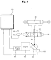
- this invention is applied to any construction equipment which comprises an engine 10, a hydraulic pump 20 connected to the engine 10, an actuator 40 connected to the hydraulic pump 20 and driving a working unit such as a boom, a control valve 50 installed on a fluid channel between the hydraulic pump 20 and the actuator 40, an operation lever 60 manipulated by an operator and generating an operating signal for driving the working unit, operating amount detecting means 70 for detecting an operating amount of the operation lever, RPM (revolutions per minute) detecting means 80 for detecting an RPM of the engine 10, a controller 90 controlling the control valve 50 in response to the operating signal depending on the operating amount of the operation lever 60 and the detecting signal depending on the RPM of the engine, and an regulator 100 controlling a displacement of the hydraulic pump 20, all of which are used in the technical field of the invention. Hence, detailed description thereof will be omitted.
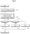
- an operating signal Pi and a detecting signal are inputted into the controller 90, wherein the operating signal Pi depends on the operating amount of the operation lever 60 which is detected by the operating amount detecting means 70, and the detecting signal depends on the RPM of the engine which is detected by the RPM detecting means 80 (S100).
- a required flow rate q depending on the operating amount of the operation lever 60 and a required flow rate q n depending on the RPM of the engine are previously determined (S200).
- step S500 When it is evaluated in step S500 that the flow rate belongs to the section to be compensated at the neutral position (i.e. when q ⁇ q n ), a controlling signal inputted from the controller 90 controls the hydraulic pump 20 to discharge the required flow rate q n for compensating the RPM of the engine (S600).
- step S500 When it is evaluated in step S500 that the required flow rate q for the operation lever is more than the required flow rate q n for compensating the engine rpm, the hydraulic pump is controlled such that the flow rate corresponding to the operating amount of the operation lever 60 is discharged (S700).
- the operating signal Pi and the detecting signal are inputted into the controller 90, wherein the operating signal Pi depends on the operating amount of the operation lever 60 which is detected by the operating amount detecting means 70, and the detecting signal depends on the RPM of the engine which is detected by the RPM detecting means 80 (S100).
- the required flow rate q depending on the operating amount of the operation lever and the required flow rate q n depending on the RPM of the engine are previously determined (S200).
- step S300 When it is evaluated in step S300 that the operation lever 60 is located at the neutral position (i.e. when Pi ⁇ Pi n and indicated by "A" in Fig. 5), a controlling signal inputted from the controller 90 to the regulator 100 controls the displacement of the hydraulic pump 20 to minimize the discharged flow rate of the hydraulic pump 20.
- step S300 if the operation lever 60 is not located at the neutral position, it is evaluated whether or not the flow rate belongs to a section to be compensated at the neutral position, on the basis of the difference between the required flow rate q depending on the operating amount of the operation lever and the required flow rate q n depending on the RPM of the engine (S500).
- step S300 When it is evaluated in step S300 that the operation lever 60 is not located at the neutral position and that the flow rate belongs to a section to be compensated at the neutral position (i.e. when q ⁇ q n and indicated by "B" in Fig. 5), a controlling signal inputted from the controller 90 controls the hydraulic pump 20 to discharge the required flow rate q n for compensating the RPM of the engine (S600).
- step S300 When it is evaluated in step S300 that the operation lever 60 is not located at the neutral position and that the required flow rate q for the operation lever is more than the required flow rate q n for the RPM of the engine ( i.e. when q > q n ), the hydraulic pump is controlled such that the flow rate corresponding to the operating amount of the operation lever 60 is discharged (S700).
- the flow rate Q discharged from the hydraulic pump 20 refers to a product of the RPM of the engine 10 and the displacement of the hydraulic pump 20 as follows.
- Q RPM x q (where q is the displacement of the hydraulic pump 20)
- the flow rate discharged from the hydraulic pump 20 is varied according to the RPM of the engine 10.
- the flow rate Q is varied due to a RPM difference of the engine caused by the working mode even when the displacement of the hydraulic pump 20 is equal.
- a spool of the control valve 50 driving the actuator (hydraulic cylinder) 40 has a different position according to the working mode under the condition that a load pressure is equal
- the displacement of the hydraulic pump 20 is controlled as small as possible (here, the RPM of the engine is high).
- the flow rate belongs to the section to be compensated at the neutral position
- the slant plate of the hydraulic pump 20 is increased (here, the RPM of the engine is low). Even if the RPM of the engine becomes different according to the working condition, when the operation lever is manipulated at the same operating amount, it can be seen that a driving amount of the actuator is identical.
- the method for compensating the flow rate when the operation lever of construction equipment is placed at the neutral position in accordance with the present invention has advantages as follows.
- the discharged flow rate of the hydraulic pump is previously set according to the working mode, and the actuator is identically driven according to the operating amount of the operation lever even when the RPM of the engine becomes different. Thereby, the manipulation capability can be improved.
Landscapes
- Engineering & Computer Science (AREA)
- General Engineering & Computer Science (AREA)
- Physics & Mathematics (AREA)
- Fluid Mechanics (AREA)
- Civil Engineering (AREA)
- Mechanical Engineering (AREA)
- Mining & Mineral Resources (AREA)
- Structural Engineering (AREA)
- Analytical Chemistry (AREA)
- Chemical & Material Sciences (AREA)
- Food Science & Technology (AREA)
- Fluid-Pressure Circuits (AREA)
- Operation Control Of Excavators (AREA)
Applications Claiming Priority (2)
| Application Number | Priority Date | Filing Date | Title |
|---|---|---|---|
| KR2004024047 | 2004-04-08 | ||
| KR1020040024047A KR100621981B1 (ko) | 2004-04-08 | 2004-04-08 | 중장비용 조이스틱 중립상태에서의 유량 보상방법 |
Publications (2)
| Publication Number | Publication Date |
|---|---|
| EP1584755A1 true EP1584755A1 (fr) | 2005-10-12 |
| EP1584755B1 EP1584755B1 (fr) | 2016-12-07 |
Family
ID=34910095
Family Applications (1)
| Application Number | Title | Priority Date | Filing Date |
|---|---|---|---|
| EP04024485.7A Active EP1584755B1 (fr) | 2004-04-08 | 2004-10-14 | Procédé pour la compensation du flux d'une pompe hydraulique pendant que la manette est dans sa position neutre |
Country Status (5)
| Country | Link |
|---|---|
| US (1) | US7269945B2 (fr) |
| EP (1) | EP1584755B1 (fr) |
| JP (1) | JP2005299917A (fr) |
| KR (1) | KR100621981B1 (fr) |
| CN (1) | CN100362174C (fr) |
Cited By (2)
| Publication number | Priority date | Publication date | Assignee | Title |
|---|---|---|---|---|
| EP2796623A4 (fr) * | 2011-12-21 | 2015-11-11 | Volvo Constr Equip Ab | Appareil pour établir un degré d'aptitude à la commande pour un engin de chantier |
| EP3249112A4 (fr) * | 2014-12-10 | 2018-12-05 | Volvo Construction Equipment AB | Procédé de compensation de débit de pompe hydraulique de machine de construction |
Families Citing this family (6)
| Publication number | Priority date | Publication date | Assignee | Title |
|---|---|---|---|---|
| KR100727625B1 (ko) * | 2005-12-31 | 2007-06-13 | 화남전자 주식회사 | 로터리 인코더를 이용한 엔진 회전수 제어 회로 및 그 방법 |
| US9234582B2 (en) * | 2009-10-21 | 2016-01-12 | Thomson Linear Llc | Apparatus and methods for controlling hydraulically-powered apparatus |
| JP5808726B2 (ja) * | 2012-11-15 | 2015-11-10 | 株式会社竹内製作所 | 油圧駆動装置 |
| JP6006666B2 (ja) * | 2013-03-28 | 2016-10-12 | 株式会社神戸製鋼所 | 油圧ショベル |
| KR102478297B1 (ko) * | 2016-01-07 | 2022-12-16 | 현대두산인프라코어(주) | 건설기계의 제어장치 및 제어방법 |
| EP3299638B1 (fr) * | 2016-09-23 | 2019-04-10 | Goodrich Actuation Systems SAS | Vanne pour actionneur electrohydrostatique |
Citations (4)
| Publication number | Priority date | Publication date | Assignee | Title |
|---|---|---|---|---|
| US5447027A (en) * | 1993-03-23 | 1995-09-05 | Hitachi Construction Machinery Co., Ltd. | Hydraulic drive system for hydraulic working machines |
| EP0848113A1 (fr) * | 1996-12-10 | 1998-06-17 | Hitachi Construction Machinery Co., Ltd. | Système de circuit hydraulique pour machine de construction hydraulique |
| EP0884422A2 (fr) * | 1997-06-12 | 1998-12-16 | Hitachi Construction Machinery Co., Ltd. | Système de commande du moteur d'une machine de chantier |
| US6173572B1 (en) * | 1999-09-23 | 2001-01-16 | Caterpillar Inc. | Method and apparatus for controlling a bypass valve of a fluid circuit |
Family Cites Families (2)
| Publication number | Priority date | Publication date | Assignee | Title |
|---|---|---|---|---|
| US6305162B1 (en) * | 1999-03-31 | 2001-10-23 | Caterpillar Inc. | Method and apparatus for controlling the deadband of a fluid system |
| US7007466B2 (en) * | 2001-12-21 | 2006-03-07 | Caterpillar Inc. | System and method for controlling hydraulic flow |
-
2004
- 2004-04-08 KR KR1020040024047A patent/KR100621981B1/ko active IP Right Grant
- 2004-09-09 US US10/937,474 patent/US7269945B2/en active Active
- 2004-09-17 JP JP2004271473A patent/JP2005299917A/ja active Pending
- 2004-10-14 EP EP04024485.7A patent/EP1584755B1/fr active Active
- 2004-10-29 CN CNB2004100901555A patent/CN100362174C/zh active Active
Patent Citations (4)
| Publication number | Priority date | Publication date | Assignee | Title |
|---|---|---|---|---|
| US5447027A (en) * | 1993-03-23 | 1995-09-05 | Hitachi Construction Machinery Co., Ltd. | Hydraulic drive system for hydraulic working machines |
| EP0848113A1 (fr) * | 1996-12-10 | 1998-06-17 | Hitachi Construction Machinery Co., Ltd. | Système de circuit hydraulique pour machine de construction hydraulique |
| EP0884422A2 (fr) * | 1997-06-12 | 1998-12-16 | Hitachi Construction Machinery Co., Ltd. | Système de commande du moteur d'une machine de chantier |
| US6173572B1 (en) * | 1999-09-23 | 2001-01-16 | Caterpillar Inc. | Method and apparatus for controlling a bypass valve of a fluid circuit |
Cited By (2)
| Publication number | Priority date | Publication date | Assignee | Title |
|---|---|---|---|---|
| EP2796623A4 (fr) * | 2011-12-21 | 2015-11-11 | Volvo Constr Equip Ab | Appareil pour établir un degré d'aptitude à la commande pour un engin de chantier |
| EP3249112A4 (fr) * | 2014-12-10 | 2018-12-05 | Volvo Construction Equipment AB | Procédé de compensation de débit de pompe hydraulique de machine de construction |
Also Published As
| Publication number | Publication date |
|---|---|
| CN1680665A (zh) | 2005-10-12 |
| EP1584755B1 (fr) | 2016-12-07 |
| KR20050098616A (ko) | 2005-10-12 |
| US20050226732A1 (en) | 2005-10-13 |
| KR100621981B1 (ko) | 2006-09-14 |
| CN100362174C (zh) | 2008-01-16 |
| JP2005299917A (ja) | 2005-10-27 |
| US7269945B2 (en) | 2007-09-18 |
Similar Documents
| Publication | Publication Date | Title |
|---|---|---|
| EP1798346B1 (fr) | Dispositif de commande pour machine à entraînement hydraulique | |
| EP0644335B1 (fr) | Moteur hydraulique pour engin de chantier hydraulique | |
| JP3210221B2 (ja) | 建設機械の制御回路 | |
| KR101778225B1 (ko) | 건설기계의 유압펌프 제어방법 | |
| EP2518222B1 (fr) | Appareil de commande de puissance pour une machine de construction | |
| EP1260716A1 (fr) | Dispositif de commande pour machine de construction | |
| EP2587072A1 (fr) | Système de commande d'écoulement pour une pompe hydraulique de machine de construction | |
| EP2660477B1 (fr) | Procédé pour commander le débit d'une pompe hydraulique à capacité variable pour un engin de chantier | |
| EP2341191A1 (fr) | Procédé de contrôle de moteur d'oscillation dans un système hydraulique de type à centre ouvert pour excavateur | |
| US11118328B2 (en) | Construction machine | |
| KR100813362B1 (ko) | 유압굴삭차량의 유압제어장치 | |
| EP2518223B1 (fr) | Appareil de commande hydraulique pour un engin de chantier | |
| EP1584755A1 (fr) | Procédé pour la compensation du flux d'une pompe hydraulique pendant que la manette est dans sa position neutre | |
| KR100651695B1 (ko) | 건설장비 제어방법 및 그 시스템 | |
| JP2005257064A (ja) | 非常時の重装備作業装置の制御方法 | |
| KR20090111964A (ko) | 에너지 절감형 유압시스템 | |
| KR20160115475A (ko) | 건설기계의 유압 펌프 제어 장치 및 제어 방법, 및 이를 포함하는 건설기계 | |
| KR101186568B1 (ko) | 작업모드 설정기능이 구비된 유압시스템 | |
| CN113474519B (zh) | 工作机器的液压控制回路 | |
| JP2008075365A (ja) | 作業機械における制御システム | |
| JP3816503B2 (ja) | 建設機械の制御装置 | |
| KR20050094128A (ko) | 작업장치용 조이스틱을 이용한 미세작업 제어방법 | |
| JP2002276610A (ja) | 建設機械の油圧シリンダ制御装置 |
Legal Events
| Date | Code | Title | Description |
|---|---|---|---|
| PUAI | Public reference made under article 153(3) epc to a published international application that has entered the european phase |
Free format text: ORIGINAL CODE: 0009012 |
|
| 17P | Request for examination filed |
Effective date: 20041014 |
|
| AK | Designated contracting states |
Kind code of ref document: A1 Designated state(s): AT BE BG CH CY CZ DE DK EE ES FI FR GB GR HU IE IT LI LU MC NL PL PT RO SE SI SK TR |
|
| AX | Request for extension of the european patent |
Extension state: AL HR LT LV MK |
|
| AKX | Designation fees paid |
Designated state(s): DE FR GB IT |
|
| 17Q | First examination report despatched |
Effective date: 20090313 |
|
| GRAP | Despatch of communication of intention to grant a patent |
Free format text: ORIGINAL CODE: EPIDOSNIGR1 |
|
| INTG | Intention to grant announced |
Effective date: 20160712 |
|
| GRAS | Grant fee paid |
Free format text: ORIGINAL CODE: EPIDOSNIGR3 |
|
| GRAA | (expected) grant |
Free format text: ORIGINAL CODE: 0009210 |
|
| AK | Designated contracting states |
Kind code of ref document: B1 Designated state(s): DE FR GB IT |
|
| REG | Reference to a national code |
Ref country code: GB Ref legal event code: FG4D |
|
| REG | Reference to a national code |
Ref country code: DE Ref legal event code: R096 Ref document number: 602004050431 Country of ref document: DE |
|
| PG25 | Lapsed in a contracting state [announced via postgrant information from national office to epo] |
Ref country code: IT Free format text: LAPSE BECAUSE OF FAILURE TO SUBMIT A TRANSLATION OF THE DESCRIPTION OR TO PAY THE FEE WITHIN THE PRESCRIBED TIME-LIMIT Effective date: 20161207 |
|
| REG | Reference to a national code |
Ref country code: DE Ref legal event code: R097 Ref document number: 602004050431 Country of ref document: DE |
|
| PLBE | No opposition filed within time limit |
Free format text: ORIGINAL CODE: 0009261 |
|
| STAA | Information on the status of an ep patent application or granted ep patent |
Free format text: STATUS: NO OPPOSITION FILED WITHIN TIME LIMIT |
|
| REG | Reference to a national code |
Ref country code: FR Ref legal event code: PLFP Year of fee payment: 14 |
|
| 26N | No opposition filed |
Effective date: 20170908 |
|
| GBPC | Gb: european patent ceased through non-payment of renewal fee |
Effective date: 20171014 |
|
| PG25 | Lapsed in a contracting state [announced via postgrant information from national office to epo] |
Ref country code: GB Free format text: LAPSE BECAUSE OF NON-PAYMENT OF DUE FEES Effective date: 20171014 |
|
| REG | Reference to a national code |
Ref country code: FR Ref legal event code: PLFP Year of fee payment: 15 |
|
| PGFP | Annual fee paid to national office [announced via postgrant information from national office to epo] |
Ref country code: FR Payment date: 20221024 Year of fee payment: 19 |
|
| PGFP | Annual fee paid to national office [announced via postgrant information from national office to epo] |
Ref country code: DE Payment date: 20220527 Year of fee payment: 19 |