EP1584514A2 - A neck rest for seats of automobiles - Google Patents
A neck rest for seats of automobiles Download PDFInfo
- Publication number
- EP1584514A2 EP1584514A2 EP05004493A EP05004493A EP1584514A2 EP 1584514 A2 EP1584514 A2 EP 1584514A2 EP 05004493 A EP05004493 A EP 05004493A EP 05004493 A EP05004493 A EP 05004493A EP 1584514 A2 EP1584514 A2 EP 1584514A2
- Authority
- EP
- European Patent Office
- Prior art keywords
- neck rest
- housing
- support portion
- lever
- extended position
- Prior art date
- Legal status (The legal status is an assumption and is not a legal conclusion. Google has not performed a legal analysis and makes no representation as to the accuracy of the status listed.)
- Granted
Links
Images


Classifications
-
- B—PERFORMING OPERATIONS; TRANSPORTING
- B60—VEHICLES IN GENERAL
- B60N—SEATS SPECIALLY ADAPTED FOR VEHICLES; VEHICLE PASSENGER ACCOMMODATION NOT OTHERWISE PROVIDED FOR
- B60N2/00—Seats specially adapted for vehicles; Arrangement or mounting of seats in vehicles
- B60N2/80—Head-rests
- B60N2/806—Head-rests movable or adjustable
- B60N2/838—Tiltable
- B60N2/862—Tiltable with means for maintaining a desired position when the seat-back is adjusted, e.g. parallelogram mechanisms
-
- B—PERFORMING OPERATIONS; TRANSPORTING
- B60—VEHICLES IN GENERAL
- B60N—SEATS SPECIALLY ADAPTED FOR VEHICLES; VEHICLE PASSENGER ACCOMMODATION NOT OTHERWISE PROVIDED FOR
- B60N2/00—Seats specially adapted for vehicles; Arrangement or mounting of seats in vehicles
- B60N2/80—Head-rests
- B60N2/888—Head-rests with arrangements for protecting against abnormal g-forces, e.g. by displacement of the head-rest
Definitions
- the invention relates to a neck rest for seats of automobiles according to claim 1.
- DE 199 61 617 A1; DE 199 51 966 A1 or DE 101 42 625 A1 have made known a neck rest which has a strut member which can be displaced towards the front on the seat user's head, and an impact member actuating the strut member. When there is an impact onto the rear end of the vehicle the impact member will be actuated and the strut member is displaced towards the front.
- the strut member is supported on the cushion holder via pivoting arms.
- the strut member forms part of the neck rest cushion which consists of two components which are connected to each other via joints.
- the impact member can interact with the strut member via a pull rope and can be in communication with a release element.
- DE 102 08 620 describes a neck rest for the seats of automobiles which has a fixed support portion and a second support portion for a movable cushion component which is movably supported in the first support portion.
- the second support portion is pivotally supported about a lower horizontal axis in the first support portion and an actuation device is defined by a spring which biases the second support portion.
- a controllable locking device maintains the second support portion in the retracted position on the first support portion.
- a third support portion is supported to be displaced on the second support portion between a lower and an upper position. The third support portion is biased by a second spring towards the upper position.
- a second controllable locking device maintains the third support portion in the lower position with the second locking device being released when the second support portion has reached a predetermined pivoting angle.
- Neck rests of this type are also referred to as crash-active neck rests. Their characteristic feature is that a seat user's head which will bounce back during a crash moves through a distance which is as short as possible until it hits against the neck rest. This distance possibly is relatively long when a passive neck rest is used and there is a risk for the head not to be supported at the proper point so that backbone lesions cannot be ruled out.
- extendable neck rests which are known is that they comprise multiple elements. This involves relative large expenditure for their manufacture, specifically for its cushion. Moreover, their appearance possibly is not very pleasing because there is a circumferential gap between the adjacent components of the known crash-active neck rest.
- a support portion is fixedly attached to the two neck rest rods.
- the neck rest body has a shroud-like housing which has a front wall and a rear wall.
- a cushion can be mounted on the front side of the front wall.
- the housing may altogether be provided with a single-piece covering.
- the support portion is located within the housing between the front and rear walls.
- the shroud-like housing is movably supported between a rear basic position in which the support portion is near or adjacent to the inner side of the front wall and an extended position in which the support portion is remote from the front wall.
- a linkage is hinged between the support portion or the neck rest rods and the front wall, respectively, and a spring arrangement biases the linkage or housing, respectively, towards the extended position.
- a releasable locking device locks the housing or linkage, respectively, in the basic position and a releasing device, upon its actuation, releases the locking device whereby the housing is moved from the basic position to the extended position.
- Strut means support the linkage or the housing in its extended position on an abutment, which prevents the neck rest body, on striking the cushion, from being moved back towards the basic position.
- the neck rest body Upon a release of the locking device, the neck rest body is rapidly advanced towards the seat user's head wherein the design of the linkage, according to an aspect of the invention, is such that the neck rest body is moved upwards at the same time, which causes the moving component to obliquely point upwards.
- the locking device is released via appropriate means detailed reference to which will not be made and which are known already from the previously described state of the art.
- the neck rest body has a housing which is more or less closed circumferentially makes it commonly possible to provide it with a cushion and a cloth covering.
- the body When the body is released and is displaced to the extended position from the basic position the body will be moved as a whole rather than individual components thereof are moved as is the case in the state of the art.
- This allows to give the neck rest body a relatively simple construction and, as was mentioned before, a particularly simple covering as is used in conventional neck rests.
- the shroud-like housing of the neck rest body preferably is open in the downward direction so that it can be slid over the neck rest rods and the support therebetween.
- a linkage can be imagined and are possible.
- an aspect of the invention provides for a scissors type linkage having a pivoting lever and a strut lever which are pivotally linked to each other between the ends.
- the pivoting lever has its upper end pivotally linked to the support portion or neck rest rods and has its lower end hingedly linked to the housing.
- the strut lever has its upper end guided approximately vertically within the housing whereas it has its lower end supported on at least one supporting surface when the neck rest body is in the extended position.
- an aspect of the invention provides that the pivoting lever is biased by a leaf spring towards the extended position. It further is useful to provide a biasing spring also between the two levers.
- an aspect of the invention provides that the strut lever is biased by a coil spring towards the extended position on its pivoting axis where at least one end of the coil spring is supported on the pivoting lever. This design allows to displace the neck rest body to the extended position particularly rapidly.
- an aspect of the invention provides for its upper end to have a guide rod which cooperates with a vertical elongated hole in the interior of the housing.
- the elongated hole is preferably located on a portion in the housing that is mounted on the inner wall, preferably the side wall of the casing.
- this elongated hole may have saw teeth on a hole wall which faces the front wall of the casing. If the impact of the head takes place while the neck rest is moving to the extended position at a time where the neck rest has not reached yet its final extended position the guide rod is adapted to engage a gap between adjacent saw teeth, thus defining a support for the bearing rod.
- the support is enhanced if the support portion, according to a further aspect of the invention, has vertically superimposed stop steps which are adapted to support the lower end of the strut lever.
- the saw teeth and steps can be designed such that the lower end of the strut lever is supported on one of the steps when the upper end has its guide rod positioned in a gap between adjacent saw teeth. In this manner, the neck rest body is also active as an impact-absorbing member in intermediate positions.
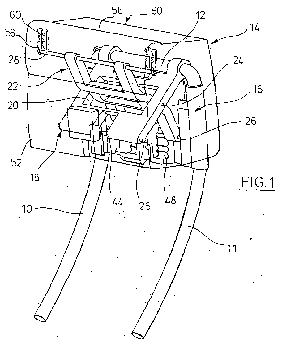
- two neck rest rods 10, 11 can be seen which are connected to each other via a transverse rod 12 at the upper end.
- the neck rest rods 10, 11 are received in appropriate receptacles in a back rest of an automobile seat which is not shown.
- the neck rest rods have mounted thereon a neck rest body 14 which will be described in detail below.
- a plate-shaped support portion 16 is fixedly linked to the neck rest rods 10, 11 at the lateral ends and extends between these two ends below the transverse rod 12 interconnecting the rest rods 10, 11.
- a pivoting lever 18 is pivotally supported on the transverse rod 12, i.e. by means of two spaced bearing rings.
- the pivoting lever 18, which is relatively broad, has a first recess 20 (Fig. 1) and a second recess 22 at the lower end.
- the recess 20 is traversed by a strut lever 22 which is pivotally supported in the middle of the recess as is outlined by the bearing pin 24 in Figs. 1 and 3.
- the strut lever 22 has two parallel-spaced arms each at the upper end and lower end.
- the lower arms support a bearing rod 26 (Figs. 1 and 3).
- the upper parallel arms support a guide rod 28.
- the guide rod 28 laterally extends horizontally outwards beyond the respective arms.
- the pivoting lever 18 is biased by a leaf spring 30 which is mounted on the transverse rod 12, namely in the direction away from the rods 10, 11.
- the bearing pin 24 has disposed thereon a coil spring 32 which supports its ends 34 on the pivoting lever 18.
- a bias has built up between the pivoting lever 18 and strut lever 22 and tends to move apart this lever in a scissors fashion as is illustrated in Fig. 1.
- Fig. 1 shows the extended position of the levers 18, 22 while the basic position can be appreciated in Fig. 3.
- a two-armed bearing projection 36 is formed which pivotally supports a locking lever 38.
- the locking lever 38 can be seen from the rear side in Figs. 2 and 4. It is biased in front of a spring 39 in a released position. It interacts with an electromagnet 40 which actuates a locking pin 42.
- the pin 22 is retracted in Figs. 2 and 4, thus enabling the locking lever 38 to be freely pivoted. On the contrary, if the pin 42 is caused to travel leftwards to the locking position the locking lever 38 will be able to lock the pivoting lever 18 and strut lever 22 in the basic position shown in Fig. 3.
- the locking lever 38 which is formed like a hook, grips over a portion of the rod 26 which extends crosswise through the lower end of the pivoting lever 18 and, by doing so, is also extended across and through the recess 22.
- the fork-like bearing device 38 extends through the recess 44, thereby allowing the locking lever 38 to grip behind the portion of the rod 26 facing it.
- a plurality of superimposed support steps 48 are laterally formed next to the bearing projection 36 in the support portion 16.
- the bearing rod 26 can support itself on one of the steps 48 in various positions of the lever 22.
- One support is shown on the uppermost step in Fig. 1.
- a step assembly which is identical to the assembly 48 is also provided on the opposite side of the bearing projection 36 for the other, lower arm of the strut lever 22.
- Figs. 1 through 4 further allow to see that a shroud-like housing 50 is slid over the described assembly from the top on the neck rest rods 10, 11.
- the housing has a front wall 52, a rear wall 54, a ceiling 56, and side walls which are not designated.
- the housing 50 is larger in width in a horizontal direction, which makes it possible for the lever assembly and the support portion 16 to bear relatively closely on the front wall 52 in the basic position of Fig. 3 whereas if the levers 18, 22 are in the extended position the rear wall 54 is relatively close to the support portion 16.
- the housing which is formed from an appropriate plastic material like the remaining components, for example, with the exception of the neck rest rods 10, 11 serves for accommodating a cushion (not shown) on the front wall 52 and a covering over the remaining components as is generally common and known for neck rests.
- the walls of the shroud 50 are shown as being transparent to make the interior clearly visible.
- the insides of the two side walls of the housing 50 have formed thereon elongate holes one of which is can be seen at 58 in Figs. 1 and 3.
- the elongate holes 58 extend approximately vertically and are fixed in a thickened or separated portion within the housing 50.
- the elongate holes 58 have saw teeth 60 on the side facing the front wall 52.
- the ends of the guide rod 28 engage the elongate holes 58 and interengage with the saw teeth 60, if required.
- the guide rod In the basic position, the guide rod is at the upper end of the elongate hole 58 (Fig. 3) whereas the rod 28 strikes the lower end of the elongate hole 60 in the extended position.
- the pivoting lever 18 is swung away from the support portion 16 and the strut lever 22 is swung away clockwise relative to the pivoting lever 18, to the positions shown in Fig. 1.
- the guide rod 28 grips under the last saw tooth of the elongate hole 58 and the bearing rod 26 rests on the uppermost step of the step assembly 48.
- the pivoting lever 18 supports itself on the strut lever 22 and this one does on one of the steps of the step assembly 48.
- the guide rod 28 prevents the bearing rod 26 from sliding off the steps 48 by causing the latter rod to get locked by the lowermost saw tooth.
- the neck rest body can be supported nevertheless in an intermediate position between the basic and extended positions since the bearing pins 26 are supported on one of the lower steps 48 and the guide rod 28 engages a gap between the upper saw teeth 60.
- the shift described for the shroud-like housing 50 is not only performed horizontally, but also has a vertical component. This is the way the neck rest cushion (not shown) is moved towards the back of seat user's head if the user shoots backwards because the vehicle experiences a crash.
Landscapes
- Engineering & Computer Science (AREA)
- Aviation & Aerospace Engineering (AREA)
- Transportation (AREA)
- Mechanical Engineering (AREA)
- Seats For Vehicles (AREA)
Abstract
Description
- Fig. 1
- shows a perspective view of a neck rest of the invention in the extended position as seen from the front side.
- Fig. 2
- shows a perspective view of a neck rest of Fig. 1 as seen from the rear side.
- Fig. 3
- shows a perspective view of a neck rest of Fig. 1 in the basic position as seen from the front side.
- Fig. 4
- shows a perspective view of a neck rest of Fig. 3 as seen from the rear side.
Claims (15)
- A neck rest for the seat of an automobile, comprising a neck rest body which includes a neck rest cushion and two neck rest rods connected with the neck rest body, the neck rest rods being accommodated in receipts in the back rest of the seat and being adapted to be lifted or lowered, comprising the following elements:a support portion (16) which is fixedly attached to the both neck rest rods (10, 11)the neck rest body (14) comprising a shroud-like housing (50) which has a front wall (52), the cushion being attached to the front side of the front wall and a rear wall (54), with the support portion (16) being located in the housing (50) between front- and rear wall (52, 54),the shroud-like housing (50) is moveable between a rear basic position wherein the support portion (16) is near or adjacent to the inner side of the front wall (52) and an extended position, wherein the support portion (16) is remote from the front wall (52),a linkage is linked between the support portion (16) or the neck rest rods (10, 11) respectively and the front wall (52),a spring arrangement biases the linkage or the housing (59) respectively towards the extended position,releasable locking means which lock the housing (50) or the linkage, respectively in the basic position,releasing means which upon actuation release the locking means whereby the housing (50) is moved from the basic position into the extended position,releasable strut means which form an abutment for the housing (50) and/or the linkage in the extended position which means prevent that upon a shock on the neck rest cushion the neck rest body (14) is moved back towards the basic position.
- The neck rest of claim 1, wherein the support portion (16) includes a support plate between the neck rest rods (10, 11).
- The neck rest of claim 1 or 2, wherein the shroud-like housing (50) is open to the lower end and can be moved around the support portion (16) and the upper end of the rods (10, 11) from above.
- The neck rest of claim 1, wherein the linkage is formed such that the neck rest body (14) upon its movement to the extended position is also moved upwardly.
- The neck rest of claim 1, wherein the linkage is a scissors type linkage having a pivoting lever (18) and a strut lever (22) which are linked to each other between their ends, the pivoting lever (18) is linked to the support portion (16) or the neck rest rods respectively with its upper end and linked to the housing (50) with its lower end, the strut lever (22) with its upper end supporting the housing (5) approximately vertically and with the lower end is supported on a supporting surface when the neck rest body (14) is in the extended position.
- The neck rest of claim 5, wherein the pivoting lever (18) is biased by a leave spring towards the extended position.
- The neck rest of claim 5 or 6, wherein the strut lever (22) is biased towards the extended position by a crew spring (32) on its pivoting axis.
- The neck rest of claim 5, wherein the pivoting lever (18) at the lower end has a horizontal bearing rod (26), the ends thereof protrude beyond the pivoting lever (18), the projection ends being accommodated by bearing openings of housing (50).
- The neck rest of claim 8, wherein the bearing rod (26) extends over an approximately central recess (23) of the pivoting lever (18), and a locking lever (38) pivotally supported by the support portion (16) cooperating with the bearing rod (26) in the recess (23).
- The neck rest of claim 5, wherein the upper end of the strut lever (22) has a guide rod (28) which cooperates with a vertical elongated hole (58) in the interior of housing (50).
- The neck rest of claim 10, wherein the wall of the vertical elongated hole (58) facing the front wall (52) is shaped by saw teeth (60).
- The neck rest of claim 5, wherein the support portion (16) has a plurality of vertically arranged stop steps (48) adapted to support the lower end of the strut lever (22) in an intermediate position between the basic and the extended position.
- The neck rest of claim 11 and 12, wherein the saw teeth (60) in the vertical elongated hole (58) and the support steps (48) are arranged relative to each other such that the strut lever (22) engages one support step (48) when the guide rod (28) is in a space between adjacent saw teeth (60).
- The neck rest of claim 5, wherein the pivoting lever (18) is linked to an upper transverse or connection rod (12) of the neck rest rod (10, 11).
- The neck rest of claim 9, wherein the locking lever (38) is maintained in the locking position by a pin (43) of an electromagnet (40) mounted to the support portion (16).
Applications Claiming Priority (2)
| Application Number | Priority Date | Filing Date | Title |
|---|---|---|---|
| DE102004017688 | 2004-04-10 | ||
| DE102004017688A DE102004017688B4 (en) | 2004-04-10 | 2004-04-10 | Headrest for automobile seats |
Publications (3)
| Publication Number | Publication Date |
|---|---|
| EP1584514A2 true EP1584514A2 (en) | 2005-10-12 |
| EP1584514A3 EP1584514A3 (en) | 2006-04-12 |
| EP1584514B1 EP1584514B1 (en) | 2009-07-29 |
Family
ID=34895564
Family Applications (1)
| Application Number | Title | Priority Date | Filing Date |
|---|---|---|---|
| EP05004493A Expired - Lifetime EP1584514B1 (en) | 2004-04-10 | 2005-03-02 | A neck rest for seats of automobiles |
Country Status (4)
| Country | Link |
|---|---|
| US (1) | US7284793B2 (en) |
| EP (1) | EP1584514B1 (en) |
| DE (2) | DE102004017688B4 (en) |
| ES (1) | ES2330646T3 (en) |
Cited By (3)
| Publication number | Priority date | Publication date | Assignee | Title |
|---|---|---|---|---|
| EP1949820A4 (en) * | 2005-11-17 | 2012-03-28 | Aisin Seiki | HEADREST DEVICE |
| CN104797171A (en) * | 2012-09-26 | 2015-07-22 | 提爱思科技股份有限公司 | Head rest |
| US20190047455A1 (en) * | 2016-02-29 | 2019-02-14 | Jifeng Automotive Interior Gmbh | Headrest with an improved adjustment device |
Families Citing this family (26)
| Publication number | Priority date | Publication date | Assignee | Title |
|---|---|---|---|---|
| WO2004062963A1 (en) | 2003-01-10 | 2004-07-29 | Alfmeier Präzision AG | Fastening device for the headrest of a vehicle seat |
| EP1577154B1 (en) | 2004-03-19 | 2007-01-17 | Alfmeier Präzision Ag Baugruppen und Systemlösungen | Vehicle seat with pivotal headrest |
| ATE421931T1 (en) | 2004-05-14 | 2009-02-15 | Alfmeier Praez Ag | VEHICLE SEAT WITH A HEADREST |
| JP4436238B2 (en) * | 2004-11-26 | 2010-03-24 | トヨタ紡織株式会社 | Headrest |
| JP4690085B2 (en) * | 2005-03-23 | 2011-06-01 | アイシン精機株式会社 | Headrest |
| US7356744B2 (en) * | 2005-05-12 | 2008-04-08 | Pc-Doctor, Inc. | Method and system for optimizing testing of memory stores |
| FR2891506B1 (en) * | 2005-10-05 | 2007-12-07 | Faurecia Sieges Automobile | HEADREST FOR VEHICLE SEAT AND SEAT COMPRISING SUCH A HEADREST |
| JP4294629B2 (en) * | 2005-10-17 | 2009-07-15 | アイシン精機株式会社 | Headrest device |
| DE102005056816A1 (en) | 2005-11-24 | 2007-05-31 | Hydac Electronic Gmbh | Releasing device for control section, has control device pivotably arranged parallel to axis and including locking part that is released by using operating part by control device which releases moving web for control part to be controlled |
| DE102006016270B4 (en) * | 2006-04-06 | 2010-12-02 | Faurecia Autositze Gmbh | Headrest for motor vehicle seats |
| US20070246989A1 (en) * | 2006-04-21 | 2007-10-25 | Brockman Mark A | Adjustable headrest |
| DE102007005737B4 (en) | 2007-01-31 | 2010-06-10 | Alfmeier Präzision AG Baugruppen und Systemlösungen | Headrest system for a vehicle seat |
| JP5059485B2 (en) * | 2007-05-25 | 2012-10-24 | 有限会社オダ技商 | Headrest device |
| US8205941B2 (en) | 2008-07-30 | 2012-06-26 | Trw Vehicle Safety Systems Inc. | Active head restraint for a vehicle seat |
| DE102008045021B3 (en) * | 2008-08-29 | 2009-10-29 | Itw Automotive Products Gmbh | Headrest for vehicle, has impact plate with guide guiding pivoting movement of impact plate around axis such that plate is maintained in angular position against bracket during movement of plate from rest position into accident position |
| DE102009019439B3 (en) * | 2008-11-10 | 2010-06-24 | Grammer Ag | Headrest for vehicle seats |
| DE102010003109B9 (en) * | 2009-04-22 | 2012-12-13 | Lear Corporation | Seat arrangement with movable headrest |
| DE102011009659B4 (en) | 2010-09-24 | 2023-05-17 | Adient Us Llc | Headrest with an adjustable head rest surface |
| US8899685B2 (en) | 2012-06-27 | 2014-12-02 | Porter Group, Llc | Vehicle seat headrest assembly having vertical and longitudinal adjustment |
| ES2680356T3 (en) * | 2015-03-05 | 2018-09-06 | Manufactures Industrials De Tortellà, Sa | Zip seal that provides a barrier against the passage of particles or organisms through it |
| US9789794B1 (en) * | 2016-07-19 | 2017-10-17 | Ford Global Technologies, Llc | Active head restraint |
| DE102019200101B4 (en) | 2019-01-07 | 2023-10-19 | Adient Us Llc | Adjustment mechanism and headrest |
| CN109733261B (en) * | 2019-02-01 | 2024-03-08 | 安道拓(重庆)汽车部件有限公司 | car seat neck brace |
| CN110356304B (en) * | 2019-08-28 | 2023-12-29 | 安道拓(重庆)汽车部件有限公司 | Neck brace support assembly and seat with same |
| DE102022116985B4 (en) * | 2022-07-07 | 2026-04-16 | Grammer Aktiengesellschaft | Method and device for mounting a headrest for a vehicle seat |
| DE102024203686B4 (en) * | 2024-04-19 | 2026-01-22 | Adient Us Llc | HEADREST |
Citations (4)
| Publication number | Priority date | Publication date | Assignee | Title |
|---|---|---|---|---|
| DE19951966A1 (en) | 1999-10-28 | 2001-05-03 | Bayerische Motoren Werke Ag | Headrest for vehicle seats is mounted on support pillars fitted into seat backrest and two pivot levers link headrest to cushion section to swing cushion from rest position to operating position |
| DE19961617A1 (en) | 1999-12-21 | 2001-07-12 | Daimler Chrysler Ag | Headrest on seat back in motor vehicle has support component with support frame inside headrest cushion and extending in front of cushion support, and support frame can pivot on cushion support by swivel arms |
| DE10142625A1 (en) | 2001-08-31 | 2003-04-30 | Itw Automotive Prod Gmbh & Co | Headrest for automobile seats |
| DE10208620C1 (en) | 2002-02-27 | 2003-07-24 | Itw Automotive Prod Gmbh & Co | Headrest for automobile passenger seat has 2 adjustable components deployed for cushioning head and neck in rear impact situation |
Family Cites Families (12)
| Publication number | Priority date | Publication date | Assignee | Title |
|---|---|---|---|---|
| US4657304A (en) * | 1986-06-06 | 1987-04-14 | Itt Corporation | Adjustable headrest |
| GB2194729B (en) * | 1986-09-04 | 1990-03-14 | Gen Motors Corp | Improved vehicle headrest |
| US4778218A (en) * | 1986-12-12 | 1988-10-18 | Prince Corporation | Adjustable headrest |
| US5020855A (en) * | 1990-02-09 | 1991-06-04 | Prince Corporation | Adjustable headrest |
| DE19707998B4 (en) * | 1997-02-27 | 2007-04-05 | Inova Gmbh Technische Entwicklungen | Automotive seat |
| DE19644086B4 (en) * | 1996-10-31 | 2005-08-11 | C. Rob. Hammerstein Gmbh & Co. Kg | Headrest for a motor vehicle seat |
| US6213548B1 (en) * | 1999-08-12 | 2001-04-10 | Trw Inc. | Head restraint apparatus |
| DE19941712C1 (en) * | 1999-09-02 | 2000-10-26 | Daimler Chrysler Ag | Vehicle seat headrest has a leading section which is moved forwards and backwards by a scissors mechanism operated by a push member from a unit within the backrest |
| JP2004518575A (en) * | 2001-02-24 | 2004-06-24 | カイペル ゲーエムベーハー アンド カンパニー カーゲー | Head restraints for vehicle seats |
| US6767064B2 (en) * | 2002-02-27 | 2004-07-27 | Lear Corporation | Translatable head restraint for automotive seat backrest |
| DE10215054B4 (en) * | 2002-04-05 | 2007-01-18 | Keiper Gmbh & Co.Kg | Headrest for a vehicle seat |
| DE10224060C1 (en) * | 2002-05-31 | 2003-07-24 | Daimler Chrysler Ag | Headrest for automobile passenger seat adjustable between different working positions and returned to initial position in rear impact situation |
-
2004
- 2004-04-10 DE DE102004017688A patent/DE102004017688B4/en not_active Expired - Fee Related
-
2005
- 2005-03-02 DE DE602005015636T patent/DE602005015636D1/en not_active Expired - Lifetime
- 2005-03-02 EP EP05004493A patent/EP1584514B1/en not_active Expired - Lifetime
- 2005-03-02 ES ES05004493T patent/ES2330646T3/en not_active Expired - Lifetime
- 2005-03-23 US US11/086,350 patent/US7284793B2/en not_active Expired - Lifetime
Patent Citations (4)
| Publication number | Priority date | Publication date | Assignee | Title |
|---|---|---|---|---|
| DE19951966A1 (en) | 1999-10-28 | 2001-05-03 | Bayerische Motoren Werke Ag | Headrest for vehicle seats is mounted on support pillars fitted into seat backrest and two pivot levers link headrest to cushion section to swing cushion from rest position to operating position |
| DE19961617A1 (en) | 1999-12-21 | 2001-07-12 | Daimler Chrysler Ag | Headrest on seat back in motor vehicle has support component with support frame inside headrest cushion and extending in front of cushion support, and support frame can pivot on cushion support by swivel arms |
| DE10142625A1 (en) | 2001-08-31 | 2003-04-30 | Itw Automotive Prod Gmbh & Co | Headrest for automobile seats |
| DE10208620C1 (en) | 2002-02-27 | 2003-07-24 | Itw Automotive Prod Gmbh & Co | Headrest for automobile passenger seat has 2 adjustable components deployed for cushioning head and neck in rear impact situation |
Cited By (11)
| Publication number | Priority date | Publication date | Assignee | Title |
|---|---|---|---|---|
| EP1949820A4 (en) * | 2005-11-17 | 2012-03-28 | Aisin Seiki | HEADREST DEVICE |
| CN104797171A (en) * | 2012-09-26 | 2015-07-22 | 提爱思科技股份有限公司 | Head rest |
| EP2901894A4 (en) * | 2012-09-26 | 2016-06-08 | Ts Tech Co Ltd | HEAD SUPPORT |
| US9789795B2 (en) | 2012-09-26 | 2017-10-17 | Ts Tech Co., Ltd. | Head rest |
| EP3235401A1 (en) * | 2012-09-26 | 2017-10-25 | TS Tech Co., Ltd. | Head rest |
| CN107901807A (en) * | 2012-09-26 | 2018-04-13 | 提爱思科技股份有限公司 | Headrest |
| CN104797171B (en) * | 2012-09-26 | 2018-05-15 | 提爱思科技股份有限公司 | Head rest |
| EP3378356A1 (en) * | 2012-09-26 | 2018-09-26 | TS Tech Co., Ltd. | Head rest |
| US10449881B2 (en) | 2012-09-26 | 2019-10-22 | Ts Tech Co., Ltd. | Head rest |
| US20190047455A1 (en) * | 2016-02-29 | 2019-02-14 | Jifeng Automotive Interior Gmbh | Headrest with an improved adjustment device |
| US10654389B2 (en) * | 2016-02-29 | 2020-05-19 | Jifeng Automotive Interior Gmbh | Headrest with an improved adjustment device |
Also Published As
| Publication number | Publication date |
|---|---|
| EP1584514B1 (en) | 2009-07-29 |
| DE102004017688B4 (en) | 2010-02-11 |
| US20050225144A1 (en) | 2005-10-13 |
| DE102004017688A1 (en) | 2005-11-03 |
| DE602005015636D1 (en) | 2009-09-10 |
| EP1584514A3 (en) | 2006-04-12 |
| ES2330646T3 (en) | 2009-12-14 |
| US7284793B2 (en) | 2007-10-23 |
Similar Documents
| Publication | Publication Date | Title |
|---|---|---|
| EP1584514B1 (en) | A neck rest for seats of automobiles | |
| CA2473484C (en) | A neck rest for the seat of an automobile | |
| US6523899B1 (en) | Automated fold and tumble vehicle seat assembly | |
| US6805411B2 (en) | Neck rest for the seats of automobiles | |
| JP4143032B2 (en) | Headrest configuration | |
| JP3759907B2 (en) | Seat device with foldable backrest | |
| US6074011A (en) | Automatic retractable head restraint | |
| US9475415B2 (en) | Headrest dump assembly with both cable and push button actuation | |
| US8197007B2 (en) | Combination pivotal and displaceable headrest assembly incorporated into a vehicle seat | |
| US8297684B1 (en) | Folding armrest | |
| CA2399190C (en) | Neck rest for a seat for automobiles | |
| US20070284929A1 (en) | Motor-vehicle headrest | |
| EP2644446B1 (en) | Headrest for motor vehicle seats | |
| ITMI970198A1 (en) | TILTING BACKREST FOR SEATS FOR VEHICLES IN PARTICULAR SEATS WITH HEIGHT ADJUSTABLE HEADREST | |
| CN101293490B (en) | Automobile | |
| JP2004526626A (en) | Motor seat with motor | |
| JP4790727B2 (en) | Adjustable seat | |
| EP1475267B1 (en) | Child safety seat | |
| CN101301865B (en) | Automobile | |
| KR100622700B1 (en) | Sliding device of headrest | |
| CN101107147B (en) | Backrest arrangement for a motor vehicle seat | |
| JP5213133B2 (en) | Bracket system adapted for use in adjustable headrest lifting and lowering mechanisms of automobile seats | |
| EP2014506A1 (en) | Motor-vehicle seat having a headrest with an anti-whiplash upward sliding movement | |
| KR100764702B1 (en) | Lever unit for pumping and reclining seats | |
| EP3674136A1 (en) | Head restraint with active deployment |
Legal Events
| Date | Code | Title | Description |
|---|---|---|---|
| PUAI | Public reference made under article 153(3) epc to a published international application that has entered the european phase |
Free format text: ORIGINAL CODE: 0009012 |
|
| 17P | Request for examination filed |
Effective date: 20050310 |
|
| AK | Designated contracting states |
Kind code of ref document: A2 Designated state(s): AT BE BG CH CY CZ DE DK EE ES FI FR GB GR HU IE IS IT LI LT LU MC NL PL PT RO SE SI SK TR |
|
| AX | Request for extension of the european patent |
Extension state: AL BA HR LV MK YU |
|
| PUAL | Search report despatched |
Free format text: ORIGINAL CODE: 0009013 |
|
| AK | Designated contracting states |
Kind code of ref document: A3 Designated state(s): AT BE BG CH CY CZ DE DK EE ES FI FR GB GR HU IE IS IT LI LT LU MC NL PL PT RO SE SI SK TR |
|
| AX | Request for extension of the european patent |
Extension state: AL BA HR LV MK YU |
|
| AKX | Designation fees paid |
Designated state(s): DE ES FR GB IT |
|
| 17Q | First examination report despatched |
Effective date: 20071116 |
|
| GRAP | Despatch of communication of intention to grant a patent |
Free format text: ORIGINAL CODE: EPIDOSNIGR1 |
|
| GRAS | Grant fee paid |
Free format text: ORIGINAL CODE: EPIDOSNIGR3 |
|
| GRAA | (expected) grant |
Free format text: ORIGINAL CODE: 0009210 |
|
| AK | Designated contracting states |
Kind code of ref document: B1 Designated state(s): DE ES FR GB IT |
|
| REG | Reference to a national code |
Ref country code: GB Ref legal event code: FG4D |
|
| RAP2 | Party data changed (patent owner data changed or rights of a patent transferred) |
Owner name: ITW AUTOMOTIVE PRODUCTS GMBH & CO. KG |
|
| REF | Corresponds to: |
Ref document number: 602005015636 Country of ref document: DE Date of ref document: 20090910 Kind code of ref document: P |
|
| REG | Reference to a national code |
Ref country code: ES Ref legal event code: FG2A Ref document number: 2330646 Country of ref document: ES Kind code of ref document: T3 |
|
| PGFP | Annual fee paid to national office [announced via postgrant information from national office to epo] |
Ref country code: ES Payment date: 20100326 Year of fee payment: 6 |
|
| PLBE | No opposition filed within time limit |
Free format text: ORIGINAL CODE: 0009261 |
|
| STAA | Information on the status of an ep patent application or granted ep patent |
Free format text: STATUS: NO OPPOSITION FILED WITHIN TIME LIMIT |
|
| PGFP | Annual fee paid to national office [announced via postgrant information from national office to epo] |
Ref country code: GB Payment date: 20100326 Year of fee payment: 6 |
|
| 26N | No opposition filed |
Effective date: 20100503 |
|
| GBPC | Gb: european patent ceased through non-payment of renewal fee |
Effective date: 20110302 |
|
| PG25 | Lapsed in a contracting state [announced via postgrant information from national office to epo] |
Ref country code: GB Free format text: LAPSE BECAUSE OF NON-PAYMENT OF DUE FEES Effective date: 20110302 |
|
| REG | Reference to a national code |
Ref country code: ES Ref legal event code: FD2A Effective date: 20120424 |
|
| PGFP | Annual fee paid to national office [announced via postgrant information from national office to epo] |
Ref country code: IT Payment date: 20120323 Year of fee payment: 8 |
|
| PG25 | Lapsed in a contracting state [announced via postgrant information from national office to epo] |
Ref country code: ES Free format text: LAPSE BECAUSE OF NON-PAYMENT OF DUE FEES Effective date: 20110303 |
|
| REG | Reference to a national code |
Ref country code: DE Ref legal event code: R081 Ref document number: 602005015636 Country of ref document: DE Owner name: ITW AUTOMOTIVE PRODUCTS GMBH, DE Free format text: FORMER OWNER: ITW AUTOMOTIVE PRODUCTS GMBH, 58642 ISERLOHN, DE Effective date: 20130502 |
|
| PG25 | Lapsed in a contracting state [announced via postgrant information from national office to epo] |
Ref country code: IT Free format text: LAPSE BECAUSE OF NON-PAYMENT OF DUE FEES Effective date: 20130302 |
|
| PGFP | Annual fee paid to national office [announced via postgrant information from national office to epo] |
Ref country code: FR Payment date: 20140317 Year of fee payment: 10 |
|
| REG | Reference to a national code |
Ref country code: FR Ref legal event code: ST Effective date: 20151130 |
|
| PG25 | Lapsed in a contracting state [announced via postgrant information from national office to epo] |
Ref country code: FR Free format text: LAPSE BECAUSE OF NON-PAYMENT OF DUE FEES Effective date: 20150331 |
|
| REG | Reference to a national code |
Ref country code: DE Ref legal event code: R079 Ref document number: 602005015636 Country of ref document: DE Free format text: PREVIOUS MAIN CLASS: B60N0002480000 Ipc: B60N0002800000 |
|
| PGFP | Annual fee paid to national office [announced via postgrant information from national office to epo] |
Ref country code: DE Payment date: 20190327 Year of fee payment: 15 |
|
| REG | Reference to a national code |
Ref country code: DE Ref legal event code: R119 Ref document number: 602005015636 Country of ref document: DE |
|
| PG25 | Lapsed in a contracting state [announced via postgrant information from national office to epo] |
Ref country code: DE Free format text: LAPSE BECAUSE OF NON-PAYMENT OF DUE FEES Effective date: 20201001 |