EP1584455B1 - Machine for forming boxes - Google Patents
Machine for forming boxes Download PDFInfo
- Publication number
- EP1584455B1 EP1584455B1 EP05007733A EP05007733A EP1584455B1 EP 1584455 B1 EP1584455 B1 EP 1584455B1 EP 05007733 A EP05007733 A EP 05007733A EP 05007733 A EP05007733 A EP 05007733A EP 1584455 B1 EP1584455 B1 EP 1584455B1
- Authority
- EP
- European Patent Office
- Prior art keywords
- box
- boxing machine
- erecting
- lateral walls
- Prior art date
- Legal status (The legal status is an assumption and is not a legal conclusion. Google has not performed a legal analysis and makes no representation as to the accuracy of the status listed.)
- Expired - Lifetime
Links
- 238000004806 packaging method and process Methods 0.000 description 2
- 239000002537 cosmetic Substances 0.000 description 1
- 230000007547 defect Effects 0.000 description 1
- 238000000034 method Methods 0.000 description 1
Images

Classifications
-
- B—PERFORMING OPERATIONS; TRANSPORTING
- B65—CONVEYING; PACKING; STORING; HANDLING THIN OR FILAMENTARY MATERIAL
- B65B—MACHINES, APPARATUS OR DEVICES FOR, OR METHODS OF, PACKAGING ARTICLES OR MATERIALS; UNPACKING
- B65B43/00—Forming, feeding, opening or setting-up containers or receptacles in association with packaging
- B65B43/42—Feeding or positioning bags, boxes, or cartons in the distended, opened, or set-up state; Feeding preformed rigid containers, e.g. tins, capsules, glass tubes, glasses, to the packaging position; Locating containers or receptacles at the filling position; Supporting containers or receptacles during the filling operation
- B65B43/54—Means for supporting containers or receptacles during the filling operation
-
- B—PERFORMING OPERATIONS; TRANSPORTING
- B65—CONVEYING; PACKING; STORING; HANDLING THIN OR FILAMENTARY MATERIAL
- B65B—MACHINES, APPARATUS OR DEVICES FOR, OR METHODS OF, PACKAGING ARTICLES OR MATERIALS; UNPACKING
- B65B43/00—Forming, feeding, opening or setting-up containers or receptacles in association with packaging
- B65B43/26—Opening or distending bags; Opening, erecting, or setting-up boxes, cartons, or carton blanks
- B65B43/30—Opening or distending bags; Opening, erecting, or setting-up boxes, cartons, or carton blanks by grippers engaging opposed walls, e.g. suction-operated
- B65B43/305—Opening or distending bags; Opening, erecting, or setting-up boxes, cartons, or carton blanks by grippers engaging opposed walls, e.g. suction-operated specially adapted for boxes, cartons or carton blanks
-
- B—PERFORMING OPERATIONS; TRANSPORTING
- B31—MAKING ARTICLES OF PAPER, CARDBOARD OR MATERIAL WORKED IN A MANNER ANALOGOUS TO PAPER; WORKING PAPER, CARDBOARD OR MATERIAL WORKED IN A MANNER ANALOGOUS TO PAPER
- B31B—MAKING CONTAINERS OF PAPER, CARDBOARD OR MATERIAL WORKED IN A MANNER ANALOGOUS TO PAPER
- B31B2100/00—Rigid or semi-rigid containers made by folding single-piece sheets, blanks or webs
-
- B—PERFORMING OPERATIONS; TRANSPORTING
- B31—MAKING ARTICLES OF PAPER, CARDBOARD OR MATERIAL WORKED IN A MANNER ANALOGOUS TO PAPER; WORKING PAPER, CARDBOARD OR MATERIAL WORKED IN A MANNER ANALOGOUS TO PAPER
- B31B—MAKING CONTAINERS OF PAPER, CARDBOARD OR MATERIAL WORKED IN A MANNER ANALOGOUS TO PAPER
- B31B2120/00—Construction of rigid or semi-rigid containers
- B31B2120/30—Construction of rigid or semi-rigid containers collapsible; temporarily collapsed during manufacturing
-
- B—PERFORMING OPERATIONS; TRANSPORTING
- B31—MAKING ARTICLES OF PAPER, CARDBOARD OR MATERIAL WORKED IN A MANNER ANALOGOUS TO PAPER; WORKING PAPER, CARDBOARD OR MATERIAL WORKED IN A MANNER ANALOGOUS TO PAPER
- B31B—MAKING CONTAINERS OF PAPER, CARDBOARD OR MATERIAL WORKED IN A MANNER ANALOGOUS TO PAPER
- B31B50/00—Making rigid or semi-rigid containers, e.g. boxes or cartons
- B31B50/004—Closing boxes
-
- B—PERFORMING OPERATIONS; TRANSPORTING
- B31—MAKING ARTICLES OF PAPER, CARDBOARD OR MATERIAL WORKED IN A MANNER ANALOGOUS TO PAPER; WORKING PAPER, CARDBOARD OR MATERIAL WORKED IN A MANNER ANALOGOUS TO PAPER
- B31B—MAKING CONTAINERS OF PAPER, CARDBOARD OR MATERIAL WORKED IN A MANNER ANALOGOUS TO PAPER
- B31B50/00—Making rigid or semi-rigid containers, e.g. boxes or cartons
- B31B50/02—Feeding or positioning sheets, blanks or webs
- B31B50/04—Feeding sheets or blanks
- B31B50/06—Feeding sheets or blanks from stacks
- B31B50/062—Feeding sheets or blanks from stacks from the underside of a magazine
-
- B—PERFORMING OPERATIONS; TRANSPORTING
- B31—MAKING ARTICLES OF PAPER, CARDBOARD OR MATERIAL WORKED IN A MANNER ANALOGOUS TO PAPER; WORKING PAPER, CARDBOARD OR MATERIAL WORKED IN A MANNER ANALOGOUS TO PAPER
- B31B—MAKING CONTAINERS OF PAPER, CARDBOARD OR MATERIAL WORKED IN A MANNER ANALOGOUS TO PAPER
- B31B50/00—Making rigid or semi-rigid containers, e.g. boxes or cartons
- B31B50/74—Auxiliary operations
- B31B50/76—Opening and distending flattened articles
- B31B50/80—Pneumatically
- B31B50/804—Pneumatically using two or more suction devices on a rotating element
Definitions
- the boxing machine 1 presents some advantages, deriving mainly from the fact that the boxes 4 are withdrawn from the magazine 2 by the suction cups 20 and then they are transferred by the suction cups 31 and 42, which keep the boxes 4 without releasing them during the steps of erecting, marking of the flaps 9 of the relative ends 7b, closing the ends 7b and of introducing into the relative pockets 52.
- the boxing machine 1 presents another advantage deriving from the fact that the pockets 52 of variable width allow the operator to avoid the equipping the pockets 52 in function of the size of the boxes 4, used each time.
- both the conveying and erecting device 15 and the pocket filling conveyor 17 can be installed in a boxing machine operated in a continuous way.
Landscapes
- Engineering & Computer Science (AREA)
- Mechanical Engineering (AREA)
- Container Filling Or Packaging Operations (AREA)
- Supplying Of Containers To The Packaging Station (AREA)
Description
- The present invention relates to a method for conveying and erecting of boxes.
- There are known so-called boxing machines among the machines for packaging products, in particular cosmetic products.
- The boxing machine includes an inlet magazine, for housing a pile of tubular boxes, each of which has a plurality of walls defined by pre-weakened folding lines and is in an initial flat blank configuration, in which the box is arranged with two overlapped layers, each of which is defined by two adjacent walls of the box.
- The boxing machine includes also a device for withdrawing and transferring the boxes, which has a picking up device, which picks up the boxes, one by one, from the inlet magazine, engages each box on a relative wall, and feeds the boxes, one by one, to a pocket filling conveyor.
- Document
US 3.242.827 describes an apparatus for opening cartons of this kind, which comprises a turret-type feeder or assembly, a carton magazine and a conventional filling conveyor. The feeder comprises a stationary center column which rotatably mounts a continuously rotating bowl assembly. Continuous rotation of the bowl assembly functions to carry the pod assembly and thus the gradually opened carton to conveyor. The conveyor comprises an endless belt member on which is mounted a plurality of spaced abutments. The cartons are received between these abutment whereafter the packaging operation is completed. - In other boxing machines of this kind, the filling conveyor includes two chains, which move in respective planes, substantially parallel to each other, and which have a plurality of pushing elements, extending between the chains, uniformly distributed along the chains, and moved by the chains along a prefixed endless path.
- Each pushing element separates two adjacent pockets of the filling conveyor.
- Each of the pockets receives and keeps a relative box and its length, measured parallel to the path, approximates by excess to the dimension of a box, likewise measured parallel to the path.
- Two lateral guides, connected to the filling conveyor, extend on the opposite sides of the pushing elements to define a boxes feeding channel. A lower guide supports the lower part of the boxes.
- Each box reaches, inside a relative pocket, a final erected configuration, in which the box has a parallelogram section and has also a first end open, which is closed immediately, and a second end open, which is first left open, in order to allow the feeding of at least one article into the box.
- The needs of the market require various types of boxes, which differ one from another by e.g. dimensions.
- The known boxing machines of the above described type present a serious disadvantage deriving from the fact that the adjustment of the position of the pushing elements along the chains, necessary for adapting the length of the pockets to the dimensions of the boxes used each time by the machine, is performed manually, which results in big working difficulties for the staff and relatively long time required for setting up the machine.
- The object of the present invention is to propose a boxing machine, which does not present the above mentioned disadvantages and which is simple and cheap to produce.
- A boxing machine proposed by the present invention is obtained in accordance to what is claimed in claim 1.
- Now the present invention will be described with reference to the enclosed drawings, showing a non limiting embodiment, in which:
- Figure 1 is a perspective, schematic view, with some parts removed for sake of clarity, of a preferred embodiment of the boxing machine proposed by the present invention;
- Figure 2 is a perspective, schematic view, with some parts removed for sake of clarity, of a first detail of Figure 1;
- Figure 3 is a lateral, schematic view, with some parts in section and some parts removed for sake of clarity, of a second particular of Figure 1; and
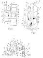
- Figures from 4 to 6 are perspective and schematic views of the boxing machine of Figure 1, in three different working positions.
- With reference to Figures 1 and 5, the reference numeral 1 indicates a boxing machine as a whole, which includes a magazine 2, receiving a pile 3 of
tubular boxes 4. - Each of the
tubular boxes 4 has, in a final, erected configuration, a parallelogram section defined by a pair ofparallel walls 5, a pair ofparallel walls 6, perpendicular to thewalls 5, and by two open ends 7, each of which is defined, in this case, by twowings 8 connected to thewalls 5 and by aflap 9, connected to one of thewalls 6. - Each
wall adjacent wall pre-weakened folding line 10 and, likewise, eachwing 8 is connected to therelative wall 5 and eachflap 9 is connected to therelative wall 6 by further pre-weakenedfolding lines 10. - Each
box 4 is arranged inside the magazine 2 in vertical position, with one of the ends 7 (from now on indicated with 7a) situated above the other end 7 (from now on indicated with 7b), and in an initial flat configuration, in which thewalls layers 11, 12 (Figure 4), substantially touching each other. - Each of the
layers respective walls - According to what has been shown in Figure 1, the machine 1 includes a withdrawing device 13 for withdrawing the
boxes 4, one by one, from the magazine 2, in aloading station 14. - A conveying and erecting
device 15 receives, one after the other, theboxes 4 from the device 13 and feeds them along a path P, extending between thestation 14 and astation 16, in which theboxes 4 are transferred to apocket filling conveyor 17. - Then, the conveying and erecting
device 15 erects theboxes 4 and closes therelative ends 7b during theboxes 4 feeding along the path P. - The device 13 includes a picking up
device 18, which comprises aplate 19 equipped with a pair of suction cups 20, connected to a suction device of known type, not shown, and fastened to one end of aslide 21 coupled in known way to aturret 22. - The
slide 21 can be oriented to perform straight movements with respect to theturret 22. - The
turret 22 is coupled rotatingly to astationary frame 24 of the machine 1, so that it can rotate with respect to theframe 24 and due to the push of an operating device of known type, not shown, on a rotating axis 25, substantially vertical. - With reference to Figure 2, the
device 15 includes adrum 26, which is mounted rotating on theframe 24, rotated in steps with respect to theframe 24 due to the push of a known and not shown motor, on anaxis 27, parallel to the axis 25. - The
drum 26 supports a plurality of conveying and erecting units 28 (in the present case six units 28), regularly distributed along the edge of thedrum 26. - Each
unit 28 includes a first picking upelement 29, comprising aplate 30, which is substantially L-like and which is equipped with a pair ofsuction cups 31, connected to the suction device (not shown). - The
plate 30 is fastened to an end of aslide 32 coupled in known way to thedrum 26, in order to perform straight movements, due to the push of anactuator device 33, operated in thestations radial direction 34, between a rear position (Figure 2) and a withdrawn position (not shown). - The
device 33 includes arack 35, fastened to theslide 32 parallel to thedirection 34, and coupled to atoothed section 36, which is integral with ashaft 37, mounted rotating through thedrum 26, to oscillate with respect to thedrum 26 and due to the push of alinkage 38, shown only partially in Figure 2, on arotating axis 39 parallel to theaxis 27. - The
unit 28 includes also a second picking upelement 40, comprising aflat plate 41, which has a pair ofsuction cups 42 connected to the suction device (not shown), and which is fastened to one end of ashaft 43, mounted rotating through theplate 30, to rotate with respect to theplate 30, on anaxis 44, whose fulcrum is parallel to theaxis 27. - A torsionally
flexible spring 45, set to surround theshaft 43, normally keeps theflat plate 41 in an erecting working position (figures 2 and 5), in which thesuction cups 42 are arranged orthogonal to thesuction cups 31. - The
shaft 43 has anarm 46, which extends toward the outside of theshaft 43 and supports aroller 47, coupled rotating with thearm 46 and engaging, at thestation 14 and during the movement of theunit 28 between its rear and withdrawn positions, with apath 48, substantially straight, arranged at an angle different from zero with respect to thedirection 34. - The orientation of the
path 48 with respect to thedirection 34 is such that: - during the movement of the
unit 28 from its rear position to its withdrawn position, theshaft 43 is moved clockwise on theaxis 44 in Figure 2, and against the action of thespring 45, so as to arrange theplate 41 in an engaged working position (Figure 4), in which thesuction cups 42 are arranged substantially parallel to thesuction cups 31, in order to receive abox 4 from the device 13; and - during the movement of the
unit 28 from its withdrawn position to its rear position, thetappet roll 47 cooperates with thespring 45, to move theshaft 43 counterclockwise on theaxis 44 in Figure 2 and to arrange theplate 41 again in its erecting working position. - With reference to Figures 1 and 3, the
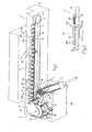
pockets filling conveyor 17 includes abelt 49, which moves in a vertical plane and which is wound endlessly on a pair ofpulleys 50, mounted on theframe 24 to rotate with respect to theframe 24 on respectivehorizontal rotation axes 51, transversal to theaxis 27. - One of the
pulleys 50 is motorized in steps. - The
conveyor 17 includes also a plurality ofpockets 52, which are distributed uniformly along thebelt 49 and are fed by thebelt 49 through thestation 16, each in step relation with a relative conveying and erectingunit 28. - Each
pocket 52 has a variable width including aflat bottom wall 53 fastened to thebelt 49, and a pair of lateral walls 54, which are mounted on theplate 53, orthogonal thereto. - The lateral walls 54 are substantially orthogonal to a
direction 55 ofpockets 52 feeding and are arranged one (later indicated with 54a) before the other (later indicated with 54b) in thedirection 55. - The
wall 54b is integral with thewall 53, while thewall 54a is coupled slidingly with thewall 53, so as to move with respect to thewall 54b in thedirection 55, and it is normally kept, by aspring 56 interposed between thewalls walls box 4 measured parallel to the path P. - The
wall 54a is moved, by anactuator 57, against the action of thespring 56 from the first working position to a second working position, in which the distance between thewalls box 4 measured parallel to the path P. - The
actuator 57 is mounted in thetransferring station 16 and engages acontrol bar 58, which protrudes from thewall 54a and engages slidingly with aslot 59 made through thewall 53 and thebelt 49. - Moreover, the
actuator 57 moves between a raised position (Figure 3), in which thebar 58 is operated and a lowered, rest position (not shown), in which theactuator 57 rests below thebar 58, in order to allow thepocket 52 to move forward in thedirection 55. - The operation of the machine 1 will be now described with reference to the enclosed figures, taking into consideration the conveying, erecting and filling of only one
box 4, and beginning from a moment, in which the picking updevice 18 is in a loading position, facing the magazine 2, and in which the conveying and erectingdevice 15 moves a conveying and erectingunit 28 toward theloading station 14. - The
slide 21 is moved through theturret 22 to allow the suction cups 20 first to engage thelayer 11 of thebox 4 in question and then, to allow the picking updevice 18 to withdraw thebox 4 from the magazine 2. - The
turret 22 is rotated around the axis 25 to move themember 18 to the transferring position, facing a conveying and erectingunit 28, which reaches its withdrawn position, when thedevice 15 dwells in thestation 14, to allow theroller 47 to engage with thepath 48 and to allow the picking upmember 40 to reach its engaging working position (Figure 4). - When the
box 4 has been released by the suction cups 20 to thesuction cups unit 28 is moved again to its rear position. - During the movement of the
unit 28 from its withdrawn position to its rear position, the picking upmember 40 moves with respect to the picking upmember 29 to reach its erecting position and to move thelayers box 4 its final, erected configuration (Figure 5). - At this point, the
device 15 is operated again to move theunit 28 in an intermittent way along the path P, first through a first closing station (not shown), in which thewings 8 of theend 7b are closed, then through a marking station (not shown), in which a code is affixed to theflap 9 of theend 7b, and finally, through a second closing station (not shown), in which theflap 9 of theend 7b, and subsequently theend 7b, are closed. - Afterwards, the
unit 28 is fed to the transferringstation 16, in step relation with apocket 52 of thepocket filling conveyor 17. - When in the
station 16, thewall 54a is moved by theactuator 57 to its second working position, against the action of thespring 56, and theunit 28 moves again to its withdrawn position, to release thebox 4 in its final erected configuration and with theend 7b closed, into thepocket 52 in question (Figure 6). - According to Figure 1, when the
box 4 has been positioned inside thepocket 52, theactuator 57 is deactivated to allow thewalls box 4 is tightened therebetween, theunit 28 is moved to its rear position to disengage thebox 4, and thebox 4 is fed by theconveyor 17, first through a succession of filling stations 60 of known type, to introduce, into thebox 4, for example anarticle 61 and aninformation leaflet 62, then through afirst closing station 63, in which thewings 8 of theend 7a are closed, and finally, through asecond closing station 64, - in which the
flap 9 of theend 7a and then theend 7a, are closed. - The boxing machine 1 presents some advantages, deriving mainly from the fact that the
boxes 4 are withdrawn from the magazine 2 by the suction cups 20 and then they are transferred by thesuction cups boxes 4 without releasing them during the steps of erecting, marking of theflaps 9 of the relative ends 7b, closing theends 7b and of introducing into the relative pockets 52. - Moreover, the boxing machine 1 presents another advantage deriving from the fact that the
pockets 52 of variable width allow the operator to avoid the equipping thepockets 52 in function of the size of theboxes 4, used each time. - Moreover, the conformation of the conveying and erecting
units 28 and of thepockets 52 allows to avoid scratches and/or damages of any type to theboxes 4. - Obviously, both the conveying and erecting
device 15 and thepocket filling conveyor 17 can be installed in a boxing machine operated in a continuous way.
Claims (9)
- Boxing machine for erecting and filling boxes (4), each box (4) being erected beginning from an initial flattened configuration, in which the box (4) is arranged in two overlapped layers (11, 12) each layer of said overlapped layers being defined by at least one wall (5, 6) of the box (4); the boxing machine including a magazine (2) for containing at least one box (4); erecting and filling means (13, 15, 17), which pick up the box (4) in its initial flattened configuration from the magazine (2), give to the box (4) its final erected configuration, in which the box (4) has a parallelogram section, and introduce at least one article (61) into the box (4); the erecting and filling means (13, 15, 17) including a pocket conveyor (17) having at least one pocket (52), and a station (16) for transferring the box (4) to the pocket (52); and being characterized in that said pocket (52), when used, has a variable geometry; with actuating means (57) controlling selectively the geometry of the pocket (52) in the transferring station (16) and allowing the introduction of the box (4) into the pocket (52) independently from the dimensions of the box (4).
- Boxing machine as claimed in claim 1, characterized in that the pocket (52) has a liberty degree controlled by said actuating means (57).
- Boxing machine as claimed in claim 1 or 2, characterized in that said pocket (52) includes a bottom wall (53) and two lateral walls (54), substantially orthogonal to the bottom wall (53) and moving one with respect to the other between a box (4) tightening position and a release position, so as to allow the box (4) to be introduced between the lateral walls (54).
- Boxing machine as claimed in claim 3, including also pushing means (56), which normally keep the lateral walls (54) in said tightening position; said pushing means (56) being carried by said pocket (52).
- Boxing machine as claimed in claim 4, characterized in that said actuating means (57) are mounted in the transferring station (16) to move the lateral walls (54), against the action of said pushing means (56), from the tightening position, to the release position.
- Boxing machine as claimed in any of the claims from 3 to 5, characterized in that said actuating means (57) move between a working position, in which the actuating means (57) are operated to engage with at least one of the lateral walls (54) and to move the lateral walls (54) to said release position, and a rest position, in which the actuating means (57) are arranged in such a way, as to allow the pocket (52) to move through the transferring station (16).
- Boxing machine as claimed in any of the previous claims, characterized in that the erecting and filling means (13, 15, 17) include also a conveying and erecting device (15), connected to the pocket conveyor (17) in said transferring station (16) and withdrawing the box (4) in its initial flattened configuration to give to the box (4) a final erected configuration.
- Boxing machine as claimed in claim 7, characterized in that the pocket conveyor (17) moves said pocket (52), in an intermittent way, through the transferring station (16) and in that the conveying and erecting device (15) moves said box (4), in an intermittent way, along a path (P) extending between the magazine (2) and the transferring station (16).
- Boxing machine as claimed in claim 7 or 8, characterized in that erecting and filling means (13, 15, 17) include also a withdrawing device (13), which transfers the box (4) from the magazine 82) to the conveying and erecting device (15).
Applications Claiming Priority (2)
| Application Number | Priority Date | Filing Date | Title |
|---|---|---|---|
| IT000210A ITBO20040210A1 (en) | 2004-04-09 | 2004-04-09 | CARTONING MACHINE |
| ITBO20040210 | 2004-04-09 |
Publications (2)
| Publication Number | Publication Date |
|---|---|
| EP1584455A1 EP1584455A1 (en) | 2005-10-12 |
| EP1584455B1 true EP1584455B1 (en) | 2007-11-07 |
Family
ID=34897767
Family Applications (1)
| Application Number | Title | Priority Date | Filing Date |
|---|---|---|---|
| EP05007733A Expired - Lifetime EP1584455B1 (en) | 2004-04-09 | 2005-04-08 | Machine for forming boxes |
Country Status (5)
| Country | Link |
|---|---|
| US (1) | US7549277B2 (en) |
| EP (1) | EP1584455B1 (en) |
| DE (1) | DE602005003155T2 (en) |
| ES (1) | ES2295998T3 (en) |
| IT (1) | ITBO20040210A1 (en) |
Families Citing this family (11)
| Publication number | Priority date | Publication date | Assignee | Title |
|---|---|---|---|---|
| ITBO20060123A1 (en) * | 2006-02-20 | 2007-08-21 | Marchesini Group Spa | METHOD FOR WITHDRAWAL OF PUNCHED TUBULARS ATTACHED BY A WAREHOUSE AND FOR THEIR MOVEMENT TO A VOLUME STATION AND EQUIPMENT THAT OPERATES THIS METHOD. |
| DE102006022656A1 (en) * | 2006-05-12 | 2007-11-15 | Robert Bosch Gmbh | Method of packaging products in wallet packs |
| DE102009050092A1 (en) * | 2009-10-20 | 2011-04-21 | Iwk Verpackungstechnik Gmbh | Transfer device for transferring a folding box |
| US9718570B1 (en) * | 2014-04-25 | 2017-08-01 | Xpak Usa, Llc | Robotic carton erector and method of use |
| CN104325710B (en) * | 2014-10-07 | 2019-03-05 | 广东鸿铭智能股份有限公司 | With the wine box shaping equipment for moving back case structure |
| IT201700017873A1 (en) * | 2017-02-17 | 2018-08-17 | Gima Spa | Unit and method for arranging objects within boxes. |
| CN112585000B (en) * | 2018-06-08 | 2023-06-30 | 诺登机械公司 | Device for erecting a folded box |
| DE102018123106A1 (en) * | 2018-09-20 | 2020-03-26 | Krones Aktiengesellschaft | Process for packaging articles and packaging system for articles such as beverage containers or the like |
| US12297000B2 (en) * | 2021-10-15 | 2025-05-13 | Berkshire Grey Operating Company, Inc. | Automated processing of container assembly systems and methods |
| MX2024006406A (en) * | 2021-11-24 | 2024-08-06 | Jones & Co Inc R A | Process and apparatus for shaping a box by wrapping around. |
| IT202200021024A1 (en) * | 2022-10-12 | 2024-04-12 | I L P R A S P A | CONVEYOR FOR CONTAINERS AND PACKAGING MACHINE |
Family Cites Families (10)
| Publication number | Priority date | Publication date | Assignee | Title |
|---|---|---|---|---|
| US3242827A (en) * | 1963-07-10 | 1966-03-29 | Fibreboard Paper Products Corp | Apparatus and method for opening cartons |
| US3613525A (en) * | 1970-01-27 | 1971-10-19 | Riegel Paper Corp | Carton-handling device |
| US3956868A (en) * | 1974-11-06 | 1976-05-18 | Federal Paper Board Company, Inc. | Carton opening, filling and closing apparatus |
| US4109444A (en) * | 1977-04-04 | 1978-08-29 | Lee Richard G | Horizontal cartoning machine |
| US4254604A (en) * | 1979-01-02 | 1981-03-10 | Redington Inc. | Cartoner and product infeed conveyor therefor |
| FR2493805B1 (en) * | 1980-11-07 | 1985-09-06 | Thimon Ets | METHOD AND MACHINE FOR CONSTITUTING, FILLING, CLOSING A CONTAINER OF GENERAL PARALLELEPIPEDIC FORM FROM A FLATTENED FORM |
| US5072573A (en) * | 1990-01-12 | 1991-12-17 | Tisma Machine Corporation | Apparatus with adjustable width trays for automatic packaging machines |
| GB9208774D0 (en) * | 1992-04-23 | 1992-06-10 | Drury Roger J | Auger conveyor |
| US5514068A (en) * | 1993-11-16 | 1996-05-07 | The Mead Corporation | Machine and method for erecting basket style cartons |
| US6446416B1 (en) * | 1999-11-03 | 2002-09-10 | R. A. Jones & Co. Inc. | Vertical insert bucket |
-
2004
- 2004-04-09 IT IT000210A patent/ITBO20040210A1/en unknown
-
2005
- 2005-04-07 US US11/100,842 patent/US7549277B2/en not_active Expired - Fee Related
- 2005-04-08 ES ES05007733T patent/ES2295998T3/en not_active Expired - Lifetime
- 2005-04-08 DE DE602005003155T patent/DE602005003155T2/en not_active Expired - Lifetime
- 2005-04-08 EP EP05007733A patent/EP1584455B1/en not_active Expired - Lifetime
Also Published As
| Publication number | Publication date |
|---|---|
| DE602005003155T2 (en) | 2008-08-21 |
| US7549277B2 (en) | 2009-06-23 |
| DE602005003155D1 (en) | 2007-12-20 |
| ITBO20040210A1 (en) | 2004-07-09 |
| EP1584455A1 (en) | 2005-10-12 |
| ES2295998T3 (en) | 2008-04-16 |
| US20050227843A1 (en) | 2005-10-13 |
Similar Documents
| Publication | Publication Date | Title |
|---|---|---|
| EP0679578B1 (en) | Packaging machine for withdrawing and opening flat folded cases and for filling them with related articles | |
| JP4454968B2 (en) | Product packing method and machine using flat cylindrical parcel | |
| JP3837436B2 (en) | Multi-pack packaging equipment | |
| US6571539B2 (en) | Packaging machine and method of carton set up | |
| US7828708B2 (en) | Case erector and sealer apparatus | |
| US5393291A (en) | Mini case erector | |
| EP3015373B1 (en) | Automatic closing group for lids of cardboard boxes formed by punching | |
| EP1584455B1 (en) | Machine for forming boxes | |
| US11505341B1 (en) | Robotic case packer platform and packing method | |
| EP3083417B1 (en) | Apparatus for feeding carton blanks from a magazine to carriers | |
| US5613828A (en) | Handling partly completed containers | |
| US6718728B2 (en) | Packing machine | |
| EP1177980B1 (en) | Packaging machine | |
| CN101132967A (en) | Packaging machine for automated packaging of products into cardboard boxes | |
| US3016808A (en) | Carton feeding and erecting mechanism | |
| EP0978449B1 (en) | Machine for packaging articles into relative boxes | |
| US3373665A (en) | Cartoning machine for vertical carton flats | |
| EP0160763B1 (en) | Case presenter apparatus and method | |
| US20050227842A1 (en) | Method and device for conveying and erecting boxes | |
| EP2794404B1 (en) | Vertical packaging machine and method | |
| EP4479313B1 (en) | Cartoning machine | |
| EP1757521B1 (en) | A machine for packing products in cases | |
| EP1334910B1 (en) | Packaging machine | |
| JP4027847B2 (en) | Side flap folding device | |
| EP1008517A1 (en) | Machine for packaging articles inside boxes made from blanks |
Legal Events
| Date | Code | Title | Description |
|---|---|---|---|
| PUAI | Public reference made under article 153(3) epc to a published international application that has entered the european phase |
Free format text: ORIGINAL CODE: 0009012 |
|
| AK | Designated contracting states |
Kind code of ref document: A1 Designated state(s): AT BE BG CH CY CZ DE DK EE ES FI FR GB GR HU IE IS IT LI LT LU MC NL PL PT RO SE SI SK TR |
|
| AX | Request for extension of the european patent |
Extension state: AL BA HR LV MK YU |
|
| 17P | Request for examination filed |
Effective date: 20060315 |
|
| AKX | Designation fees paid |
Designated state(s): DE ES FR IT |
|
| GRAP | Despatch of communication of intention to grant a patent |
Free format text: ORIGINAL CODE: EPIDOSNIGR1 |
|
| GRAS | Grant fee paid |
Free format text: ORIGINAL CODE: EPIDOSNIGR3 |
|
| GRAA | (expected) grant |
Free format text: ORIGINAL CODE: 0009210 |
|
| AK | Designated contracting states |
Kind code of ref document: B1 Designated state(s): DE ES FR IT |
|
| REF | Corresponds to: |
Ref document number: 602005003155 Country of ref document: DE Date of ref document: 20071220 Kind code of ref document: P |
|
| REG | Reference to a national code |
Ref country code: ES Ref legal event code: FG2A Ref document number: 2295998 Country of ref document: ES Kind code of ref document: T3 |
|
| ET | Fr: translation filed | ||
| PLBE | No opposition filed within time limit |
Free format text: ORIGINAL CODE: 0009261 |
|
| STAA | Information on the status of an ep patent application or granted ep patent |
Free format text: STATUS: NO OPPOSITION FILED WITHIN TIME LIMIT |
|
| 26N | No opposition filed |
Effective date: 20080808 |
|
| PGFP | Annual fee paid to national office [announced via postgrant information from national office to epo] |
Ref country code: DE Payment date: 20140424 Year of fee payment: 10 Ref country code: FR Payment date: 20140424 Year of fee payment: 10 Ref country code: IT Payment date: 20140429 Year of fee payment: 10 Ref country code: ES Payment date: 20140424 Year of fee payment: 10 |
|
| REG | Reference to a national code |
Ref country code: DE Ref legal event code: R119 Ref document number: 602005003155 Country of ref document: DE |
|
| PG25 | Lapsed in a contracting state [announced via postgrant information from national office to epo] |
Ref country code: IT Free format text: LAPSE BECAUSE OF NON-PAYMENT OF DUE FEES Effective date: 20150408 Ref country code: DE Free format text: LAPSE BECAUSE OF NON-PAYMENT OF DUE FEES Effective date: 20151103 |
|
| REG | Reference to a national code |
Ref country code: FR Ref legal event code: ST Effective date: 20151231 |
|
| PG25 | Lapsed in a contracting state [announced via postgrant information from national office to epo] |
Ref country code: FR Free format text: LAPSE BECAUSE OF NON-PAYMENT OF DUE FEES Effective date: 20150430 |
|
| REG | Reference to a national code |
Ref country code: ES Ref legal event code: FD2A Effective date: 20160531 |
|
| PG25 | Lapsed in a contracting state [announced via postgrant information from national office to epo] |
Ref country code: ES Free format text: LAPSE BECAUSE OF NON-PAYMENT OF DUE FEES Effective date: 20150409 |
|
| P01 | Opt-out of the competence of the unified patent court (upc) registered |
Effective date: 20230421 |