EP2794404B1 - Vertical packaging machine and method - Google Patents
Vertical packaging machine and method Download PDFInfo
- Publication number
- EP2794404B1 EP2794404B1 EP12824707.9A EP12824707A EP2794404B1 EP 2794404 B1 EP2794404 B1 EP 2794404B1 EP 12824707 A EP12824707 A EP 12824707A EP 2794404 B1 EP2794404 B1 EP 2794404B1
- Authority
- EP
- European Patent Office
- Prior art keywords
- containers
- product
- container
- packages
- machine
- Prior art date
- Legal status (The legal status is an assumption and is not a legal conclusion. Google has not performed a legal analysis and makes no representation as to the accuracy of the status listed.)
- Active
Links
- 238000004806 packaging method and process Methods 0.000 title claims description 49
- 238000000034 method Methods 0.000 title claims description 10
- 230000008859 change Effects 0.000 claims description 23
- 230000007246 mechanism Effects 0.000 claims description 17
- 238000012546 transfer Methods 0.000 claims description 4
- 230000003213 activating effect Effects 0.000 description 3
- 238000004026 adhesive bonding Methods 0.000 description 3
- 230000008901 benefit Effects 0.000 description 3
- 238000006073 displacement reaction Methods 0.000 description 3
- 230000004913 activation Effects 0.000 description 2
- 230000006978 adaptation Effects 0.000 description 2
- 238000013459 approach Methods 0.000 description 2
- 230000008878 coupling Effects 0.000 description 2
- 238000010168 coupling process Methods 0.000 description 2
- 238000005859 coupling reaction Methods 0.000 description 2
- 238000012545 processing Methods 0.000 description 2
- 238000013519 translation Methods 0.000 description 2
- 230000009471 action Effects 0.000 description 1
- 230000000295 complement effect Effects 0.000 description 1
- 230000003247 decreasing effect Effects 0.000 description 1
- 230000002950 deficient Effects 0.000 description 1
- 230000001419 dependent effect Effects 0.000 description 1
- 230000005484 gravity Effects 0.000 description 1
- 238000004519 manufacturing process Methods 0.000 description 1
- 238000012986 modification Methods 0.000 description 1
- 230000004048 modification Effects 0.000 description 1
- 238000011017 operating method Methods 0.000 description 1
- 238000012858 packaging process Methods 0.000 description 1
- 230000008569 process Effects 0.000 description 1
- 238000004064 recycling Methods 0.000 description 1
- 230000000284 resting effect Effects 0.000 description 1
- 230000000717 retained effect Effects 0.000 description 1
- 230000002459 sustained effect Effects 0.000 description 1
- 239000012780 transparent material Substances 0.000 description 1
- 210000001364 upper extremity Anatomy 0.000 description 1
- 238000011144 upstream manufacturing Methods 0.000 description 1
- 238000003466 welding Methods 0.000 description 1
Images


Classifications
-
- B—PERFORMING OPERATIONS; TRANSPORTING
- B65—CONVEYING; PACKING; STORING; HANDLING THIN OR FILAMENTARY MATERIAL
- B65B—MACHINES, APPARATUS OR DEVICES FOR, OR METHODS OF, PACKAGING ARTICLES OR MATERIALS; UNPACKING
- B65B39/00—Nozzles, funnels or guides for introducing articles or materials into containers or wrappers
- B65B39/02—Expansible or contractible nozzles, funnels, or guides
-
- B—PERFORMING OPERATIONS; TRANSPORTING
- B65—CONVEYING; PACKING; STORING; HANDLING THIN OR FILAMENTARY MATERIAL
- B65B—MACHINES, APPARATUS OR DEVICES FOR, OR METHODS OF, PACKAGING ARTICLES OR MATERIALS; UNPACKING
- B65B1/00—Packaging fluent solid material, e.g. powders, granular or loose fibrous material, loose masses of small articles, in individual containers or receptacles, e.g. bags, sacks, boxes, cartons, cans, or jars
- B65B1/30—Devices or methods for controlling or determining the quantity or quality or the material fed or filled
-
- B—PERFORMING OPERATIONS; TRANSPORTING
- B65—CONVEYING; PACKING; STORING; HANDLING THIN OR FILAMENTARY MATERIAL
- B65B—MACHINES, APPARATUS OR DEVICES FOR, OR METHODS OF, PACKAGING ARTICLES OR MATERIALS; UNPACKING
- B65B3/00—Packaging plastic material, semiliquids, liquids or mixed solids and liquids, in individual containers or receptacles, e.g. bags, sacks, boxes, cartons, cans, or jars
- B65B3/26—Methods or devices for controlling the quantity of the material fed or filled
-
- B—PERFORMING OPERATIONS; TRANSPORTING
- B65—CONVEYING; PACKING; STORING; HANDLING THIN OR FILAMENTARY MATERIAL
- B65B—MACHINES, APPARATUS OR DEVICES FOR, OR METHODS OF, PACKAGING ARTICLES OR MATERIALS; UNPACKING
- B65B39/00—Nozzles, funnels or guides for introducing articles or materials into containers or wrappers
- B65B39/001—Nozzles, funnels or guides for introducing articles or materials into containers or wrappers with flow cut-off means, e.g. valves
-
- B—PERFORMING OPERATIONS; TRANSPORTING
- B65—CONVEYING; PACKING; STORING; HANDLING THIN OR FILAMENTARY MATERIAL
- B65B—MACHINES, APPARATUS OR DEVICES FOR, OR METHODS OF, PACKAGING ARTICLES OR MATERIALS; UNPACKING
- B65B59/00—Arrangements to enable machines to handle articles of different sizes, to produce packages of different sizes, to vary the contents of packages, to handle different types of packaging material, or to give access for cleaning or maintenance purposes
- B65B59/001—Arrangements to enable adjustments related to the product to be packaged
-
- B—PERFORMING OPERATIONS; TRANSPORTING
- B65—CONVEYING; PACKING; STORING; HANDLING THIN OR FILAMENTARY MATERIAL
- B65B—MACHINES, APPARATUS OR DEVICES FOR, OR METHODS OF, PACKAGING ARTICLES OR MATERIALS; UNPACKING
- B65B59/00—Arrangements to enable machines to handle articles of different sizes, to produce packages of different sizes, to vary the contents of packages, to handle different types of packaging material, or to give access for cleaning or maintenance purposes
- B65B59/003—Arrangements to enable adjustments related to the packaging material
Definitions
- the present invention refers to a vertical packaging machine, with quick format change and its operating method.
- the invention refers to a vertical machine of the defined type as cartoning machines or case packers, wherein a die - cut product is formed into a box and wherein the vertical box is sustained by gripping means and filled on a carousel; the format (size) change of boxes packaged on the machine can be carried out rapidly, by adapting the packaging means to sizes of the box to be filled.
- Packaging machines, cartoning machines or case packers are known, presenting means for the adaptation to sizes of the box to be used for packaging.
- a folded carton is erected to form the box body that is retained by appropriate means movable along a path, usually a carousel, along which the box is closed on the bottom side, filled with the product and then closed on the upper side and sent to a line for further processing.
- the product is delivered by a specific machine, for example a dosing machine or a counting machine, usually placed over the packaging machine, through fixed hoppers, arranged along the box path.
- Box sizes could be various and, for this reason, known machines have means for changing the box format and treating different boxes.
- Object of the present invention is to solve afore discussed problems and to provide an automatic packaging machine allowing a rapid format change, that is a quick adaptation to boxes of different sizes, at the same time guaranteeing the quickness of packaging operations. Further object is to provide a vertical packaging machine for cartons or bags that allows also an easy control of number of pieces fed to the box or bag in addition to the format change.
- Such a machine has a supporting structure for means for carrying boxes or similar packages, one or more hoppers or others similar means for feeding product to the machine and at least one plurality of containers disposed between the hoppers and boxes (or other packages) to hold temporarily the product before its feeding to the boxes; these containers being realized with several portions in order to be able to change the dimensions of the output opening to adapt the latter to the input openings of the boxes, at least in one dimension, usually the width.
- the machine comprises two series of containers: a plurality of first containers to receive the product from dosing means and holding it temporarily and a plurality of second containers to transfer the product from the first containers to the boxes or other packages, also the second containers being composed of several portions and the position of said portions being changeable by said machine to change the width and depth of said containers as a function of the box width and depth.
- Machine containers comprise kinematic mechanisms to modify the reciprocal position of the portions of containers and then the dimensions thereof, or at least of their output opening; kinematic mechanisms are operated by the machine itself when a format change is necessary. More in particular the first containers, receiving the product from hoppers by means of dosing devices, are assembled on chains sliding along fixed guides, and at least two chains are movable in opposite directions to operate the kinematic mechanisms to change the container dimensions. A similar system for adjusting the distance between two elements is known for the distance adjustment between gripping fingers of boxes only.
- second containers they have kinematic mechanisms having, at their free end, rollers or similar engaging means, which are housed in corresponding guides present on the machine; such guides are movable in height and/ or depth, for example by warms or other actuators, so that to convey also the end of the kinematic mechanism by its motion and to operate consequently said kinematic mechanism, which in turn, moves the portions that form the container and changes the container dimensions.
- a guide and a corresponding kinematic mechanism are present to adjust the width of second containers and a further guide and kinematic mechanism to adjust the depth of second containers.
- the second containers are slidingly assembled on a base, usually a plate, so that to change the height of the container with respect to the supporting means of the box and the box they support; in particular, the second container is then vertically movable between a position in which it is adjacent to the first container to receive the dosed (and controlled) product therefrom and a position in which the output opening of the second container is adjacent and immediately over the input opening of the box to unload the product previously received from the first container therein.
- Second containers further comprise a protruding element that engages a fixed guide, said guide having a portion in which its height from the ground changes in order to carry out the container movement with respect to the base plate sustaining the container, as afore discussed, and to draw up the second container to the box below in the unloading step of product into the box.
- said gripping means of packages are assembled on said base plate, preferably slidingly, in order to treat different boxes.
- Said gripping means are integral with C-shaped elements that engage a flange - like guide assembled on the machine, said flange - like guide being movable and adjustable in height to adjust the distance between said gripping means of packages from the second container.
- the said second containers comprise at least two end elements of the kinematic mechanisms which are accommodated in two corresponding movable guides.
- four movable guides are present, three guides being adjustable vertically, in height with respect to the ground, and a guide being adjustable horizontally.
- Said horizontally adjustable guide houses the end of a horizontally translating element that bears a pusher so that to generate a surface with vertical dimension mechanically based on the box format height, this surface is intended to act as a resting wall for the box and a machine box ejector.
- the first containers follow a path different from the path of said second containers and the path of said second containers coincide with the path of said carrying and gripping means of packages.
- the containers provide a movable wall for closing the container, a lever assembled on the container to operate said wall and means assembled on the machine to operate said lever.
- Said means are flanges fixed or vertically movable, assembled on the machine.
- a further object of the invention is further a feeding container produced for a packaging machine, according to claim 10.
- the product dosed by known dosing means is fed to a plurality of first container; the dosed product in transferred by the first containers to a plurality of second containers having an output opening with dimensions and shape substantially corresponding to dimensions and shape of the input opening of packages; the product is transferred by said second containers to said packages, the product being held temporarily in containers before being transferred from the first container to the second container and from the second container to the package (box).
- dimensions and shape of the second containers are adjusted acting on width and depth of said containers.
- the invention provides that the product amount accuracy in the first containers is checked before transferring said product into said second containers. In case of incorrect amount, the dosed product is unloaded in recycling means of the latter to dosing means.
- the invention presents a number of advantages relative to the known art.
- the machine allows to check the correct product dosing before the product is fed to the box, said check being carried out in the first container. In this way the rejecting of packaged boxes is avoided and costs and process times are decreased.
- a further advantage is given by the possibility of packaging boxes having different dimensions in depth, or thickness; this becoming a manufacturing economy, that can change from a box to another almost without stopping the packaging process.
- the vertical packaging machine 31 for packages 16 such as boxes, bags and similar - hereinafter named as “boxes”, comprises a closed path 32 along which gripping means 33 are moving to grasp and carry said packages, means for feeding the product to the machine and means for directing a predetermined amount of product to the boxes 16.
- the packaging machine 31 further comprises a plurality of first feeding containers 1 of the product, closed at the bottom and disposed over the gripping means 33; the containers 1 are movable along one or more guides 34 to follow at least part of the path 32 of said gripping means 33 and boxes 16 present on said gripping means.
- the first feeding containers 1 are composed of several portions 5A, 5B, 6A, 6B, 6C and the position of said portions 5A, 5B, 6A, 6B, 6C can be changed by the machine 31 in order to modify at least the width of said containers 1.
- the packaging machine 31 is provided with a second plurality of feeding containers 21 to transfer the product from said first plurality of containers 1 to the boxes 16, where the second feeding containers 21 are composed of several portions 17A, 17B, 18A, 18B and the position of said portions 17A, 17B, 18A, 18B can be modified by the packaging machine 31 to change the width and the thickness, that is the depth, of said containers 21.
- FIG. 1 the paths of different movable elements composing the machine are emphasized, and in particular the closed path 32 of the gripping means 33 and the closed path 34 of the first feeding containers 1.
- a second plurality of feeding containers 21 is disposed, as can be seen in figure 2 , that follows an identical path (not shown in figures) upper than the path 32 of the gripping means 33, that is the containers 21 are always aligned over the gripping means 33.
- the first feeding containers 1 are carried along the closed path 34.
- the first feeding containers 1 receive the product from one or more counters 36.
- the counters dose the product inside the first containers 1 that are closed at the bottom and then holding the product itself.
- each counters 36 send the product through the feeding lines 37 to hoppers 38, visible in figure 2 , that deliver by gravity the product inside the first feeding container 1 being underneath the hopper 38 at that moment.
- the first feeding containers 1 are provided with means for changing at least one dimension of their own section, as better explained below, in order to better adapt to the product amount to be contained, depending on the size of the boxes 16.
- the containers 1 have a shutter 9 that is usually closed and being opened as the product from the first containers has to be unloaded.
- the machine is provided with means known in themselves in the art, to adjust the speed of the closed path 32 before the curve 42 of the same path, so that to slow down the first feeding container 1 under the hopper 38 for the time necessary for the product delivery.
- the hopper 38 can be fixed or, preferably, is provided with a travel to follow the first feeding containers 1 for a short length, for example of about 300 - 400 mm, necessary to deliver the product inside said feeding container 1.
- the path 34 of the machine comprises the curve 40 at which the first feeding containers 1 pass over an unload station 39.
- the packaging machine 31 is provided with means for checking the correct product delivery operations, such as for example controlling the product dosing, by means of a control carried out by the same counters 36 or other appropriate sensors.
- the packaging machine 31 detects some errors, it is able to operate on means for opening the first feeding means, in the first embodiment having the shape of a shutter 9, to operate the bottom opening of the first feeding container 1, according to procedures better explained hereinbelow, in order to evacuate the product into a unload station 39. In this way an incorrect delivery of the product to the corresponding package 16 is avoided.
- the unload station 39 is adapted to receive and contain the product and it is preferably composed of a hopper coupled to a container placed underneath the path of the first feeding containers 1.
- the unload station 39 is connected by a return line 43 to a counter (counting machine) 36, in order to return into circulation immediately the product unloaded by the first containers.
- the packaging machine 31 operates on the shutter 9, or equivalent opening means, and it delivers the product from first to second feeding containers 21.
- the second feeding containers 21 are aligned with gripping means 33 of boxes and they follow the same path.
- FIG. 2 reciprocal position of containers 1 and 21 is schematically shown on the left side, when the dosed product has to be transferred from the first to the second container; in the figure, shutter 9 of the container 1 is still closed, but the container 21 has already moved adjacent thereto with its own product input opening.
- the second feeding containers 21 too are closed at the bottom by means whose opening can be operated by the packaging machine 31.
- the means are shaped like a shutter 29, similar in shape and operation to shutter 9 of the first containers 1.
- the machine further comprises a box feeder to gripping means 33.
- the feeder provides transferring means 35 which take flat carton boxes from a store, erect them to form an open box and arrange them on gripping means 33.
- both transferring means 35 and gripping means 33 are known in the art.
- the transferring means 35 are composed of a continuous vacuum manipulator, able to take up flat carton - like packages 16 from a store, not shown in figures, and to arrange them correctly in the gripping means 33.
- the gripping means 33 are composed by two clamp elements adapted to receive the open box.
- the clamps Preferably the clamps have a variable relative distance so that to adapt to different formats of boxes 16 the packaging machine is able to operate therewith.
- Other shapes of gripping 33 and transferring 35 means arc possible, depending on type of treated packages 16, whether they are boxes, bags or similar.
- the boxes 16 are held by gripping means 33, and then they follow part of the path 32 of the same gripping means and the upper path of the second containers 21.
- gripping means 33 In the straight length of gripping means 33 comprised between the transferring means 35 and the curve 42, there are means (known in themselves) to implement the bottom closing of the boxes 16 by means of instruments known to one skilled of the art, such for example movable and/ or opposing arms with fixed parts and gluing stations.
- second feeding means 21 can be adjusted in height too, so that to come as closest as possible to the top edge of the boxes 16 when the product delivery to the latter has to happen.
- the product delivery from the second container 21 to the box below 16 starts in the area just in front of the curve 42 of the path of the gripping means 33.
- the position taken by the containers 1 and 21, when the product is unloaded from first to second containers is shown in the right side.
- the height of the second containers 21 from the ground changes between the path before the curve 42, shown on the right in figure, and where the delivery starts and the path after the first curve, shown on the left.
- Means for arranging the product in the boxes are provided at the curve 42, such as for example a vibrating plane schematized with a double line and indicated with the reference numeral 42A.
- Means for closing upper limbs of the box are disposed on the straight portion, including a gluing assembly.
- An operative station 41 is disposed along the path 32, where boxes are separated from gripping means 33 and sent to subsequent stations by means of carrying elements, in the shown embodiment composed of a conveyor belt 45.
- the packaging machine 31 is provided with sensors able to control the operations on packages 16 too. In case of processing error or absence of package 16, the corresponding second feeding container 21 does not carry out the product delivery, the product being held and reused in a successive cycle. Additional sensors are disposed upstream the reject station 44 where defective packages or packages that did not receive the product are collected, before they arrive at the station 41 and the conveyor belt 45.
- the first feeding container 1 has a generically parallelepiped shape, with a top opening 3 and a bottom opening 4.
- the top opening 3, preferably always open, is shaped like a hopper to aid the product input into the container and the bottom opening is closed by a shutter 9.
- the first feeding container 1 comprises a duct - shaped structure, formed by several portions, five portions or elements 5A, 5B, 6A, 6B, 6C in the shown embodiment; where the elements 5A and 6A are U-shaped and the remaining three elements 5B, 6B, 6C have a flat shape.
- the flat element 5B is constrained to the U-shaped element 5A by known methods (riveting, welding, etc.) so that the assembly of the two element 5A and 5B forms a portion dedicated to the product passage through the first feeding container.
- said portion for the product passage is composed of faces 5.2A, 5.3A of the U-shaped element 5A and the flat element 5B.
- the face 5.1A is used to adjust the width of the first feeding container 1, as will be described hereinafter.
- Remaining U-shaped 6A and flat 6B and 6C elements form a second element specular to that one described above.
- the flat element 6C and the L-shaped element 6A are coupled so that to form an element specular to the element 5A and the flat element 6B acts as the flat element 5B.
- the element 6C is preferably made in transparent material in order to allow the product view in the container and it is constrained to the element 6A.
- the assembly of the elements 5A and 6B is then slidingly coupled to the assembly of the elements 6A, 6B, 6C so that to form a closed element adjustable in width.
- the flat element 6B can slide along the flat element 5B and the flat element 6C can slide along the face 5.3A of the U-shaped element 5A in the same manner, whereby the first feeding container has a generically rectangular section with an adjustable dimension, along the direction indicated by the arrow 10 in figure 3 .
- the elements 5B and 6B are called flat, also if presenting flanges perpendicular to the main body to couple with corresponding U-shaped elements 5A and 6A, as can be seen in the exploded view in figure 5 .
- the container 1 comprises a "duct" portion formed by the portions or elements 5 and 6 and a cage 7 ( fig. 6 ) in which the "duct" 5-6 is slidingly assembled.
- the adjusting cage 7 is further provided with closing and opening means of the feeding container 1.
- closing and opening means of the feeding container 1 comprises a shutter 9 hinged to the adjusting cage 7 in order to rotate when it is necessary to open the container for the product unload.
- the shutter 9 is hooked to springs 11 that keep it in an usually closed position; the springs 11 are free to extend along the guides 12 obtained in the adjusting cage 7, during the opening of the shutter.
- the shutter 9 is integral with a leverage controlling the opening and closing thereof.
- the leverage comprises an adjusting roller 13 for example assembled by means of a bolt on a protrusion 20 integral with the control levers of the shutter 9 that extends in front of the face of the first feeding container 1 opposite to the chains 2.
- the machine is provided with means, described later, to adjust the relative height of the roller 13 with respect to the adjusting cage 7.
- the shutter 9 closes the bottom opening 4 of the container 1; when the roller 13 is raised, the shutter 9 rotates and opens the bottom opening 4 of the container 1.
- the container 1 is assembled on chains 2 disposed at least on one level, with at least two chains per level and preferably at least three chains per level, in order to be conveyed along the path 34.
- the container 1 is assembled on two groups of three chain rows ( fig. 3 ), each group comprising a conveying chain 2A, placed on top, and two adjusting chains 2B and 2C placed centrally and on bottom, respectively.
- FIG 3 the assembly of chains 2, 2' is shown, on which only a first feeding container 1 is assembled for facilitating the comprehension.
- the container is fixed to the chain 2A with constraining means 15 for coupling the chains with a first feeding container, not shown, side by side of the first feeding container 1 represented in figures.
- the conveying chain 2A is provided with plates that, through the respective opening 8a of the adjusting cage 7, couple rigidly with a horizontal element, not shown in figures, integral with the first feeding container 1.
- the adjusting chains 2B are provided with pins 16B adapted to be inserted into the opening 8B of the adjusting cage and to interlockingly couple with the face 5.1A of the element 5A of the container 1.
- the width adjustment of the container 1 happens by changing the reciprocal position of the portions 5 and 6 inside the cage 7, that form the "duct" part of the container; this happens by sliding the chains 2B and 2C in opposite directions, each of them being fixed to different portions (5 or 6) of the container.
- FIG 7 the view of part of the machine controlling the handling of the container 1 along the path 34 is shown.
- an element 47 having guide hollows in which the chains are slidingly housed, in particular the chains 2A, 2B and 2C are represented.
- a motor known in the art and not object of the present invention, provides for the handing of the adjusting chains.
- This motor is coupled with the head 51 containing the device of relative displacement of the adjusting chains 2B and 2C with respect to the conveying chains 2A by means of a shaft composed of a prismatic couple 46 with a cardan joint on each end; in this way the swinging movement of such a shaft along the direction 50 is allowed, made by the reciprocating translation motion of the whole assembly that guides, conveys and adjusts the containers 1.
- This reciprocating translation motion allows the decoupling of the moving speeds of the chains 2A, 2B and 2C between the portion of path 34 preceding the curve 40 and the portion of path 34 following the curve 40, while guaranteeing the optimal tension of said chains 2A, 2B and 2C in every moment.
- the feed speed of the chains 2A, 2B and 2C is subjected to fluctuations, and in particular it is slowed down during the unloading steps of product from the hoppers 38 to the first feeding containers 1.
- the feed speed of chains 2A, 2B and 2C is constant, so that to maintain the speed of the first feeding containers 1 equal to the speed of the second feeding containers 21.
- the second container 21 in the shown embodiment comprises a "duct" structure formed by portions that slide one with respect to the other, assembled in a cage 27, in its turn assembled on conveying chains along the path 32.
- the "duct” comprises two U-shaped portions 17A, 18A and two L-shaped portions 17B and 18B.
- the two elements 17A and 17B are slidingly constrained one to another so that to form a semi-portion of the second feeding container 21 shaped like a C with adjustable depth (or thickness).
- the portion 17B is provided with pins 19 that engage along the openings 22 obtained on sides of the portion 17A.
- the pins 19 are adapted to insert into guides 23 obtained on the cage 27. In this way the two portions 17A and 17B can slide one with respect to the other and at the same time they can slide with respect to the cage 27. Similar matter goes for the portions 18A and 18B, specular to just discussed portions 17A and 17B.
- the two C-shaped semi-portions whose the first is formed by the portions 17A and 17B and the second by the portions 18A and 18B, are joined in order to slide one with respect to the other.
- the portion 18A can slide with respect to portion 17A
- the portion 18B can slide with respect to the portion 17B to change the "duct" width in which the product is housed and to adjust dimensions and shape of unload opening of the container 21 according to the input opening of the box below.
- the section of the second feeding container having generically rectangular shape, can be adjusted in both dimensions, as shown by arrows 62 and 63 in figure 8 .
- coupled portions 17 and 18 have been slidingly assembled on a base plate 51.
- the plate 51 is assembled fixed on conveying chains and it is assembled on the cage 27 with rails that allow the cage to slide vertically on the plate.
- the carrying plate 51 is made integral with two conveying chains (not shown) in the connection points 52.
- adjusting means 25A - 25D of the second feeding container 21 are now described.
- the adjusting rollers 25A and 25B are shown.
- the adjusting roller 25A is made integral, in known ways, by means of screws, bolts or similar, to the adjusting cage 27 of the second feeding container 21.
- the packaging machine 31, as described later, can handle vertically an adjusting roller 25A.
- heights of the second adjusting cage 27 and the second feeding container 21 change.
- the adjusting cage 27 is forced to slide vertically along the rails 24 made integral with the carrying plate 51.
- the descent of the second feeding container 21 towards the package 16 happens through the adjusting roller 25A.
- the roller 25B is constrained to the carrying plate 51.
- the packaging machine 31 is further provided with means, as described later, adapted to handle vertically said roller 25B. Said handling of the height of the roller 25B acts on the depth of the second feeding container 21 through kinematic mechanisms (shown in schematic manner), or rather it allows the sliding of elements 17A and 18A with respect to elements 17B and 18B along the guide 22 and 23 in the direction of the arrow 62 in figure 8 . The depth of the second feeding container 21 is then adjusted through the adjusting roller 25B based on the depth of the package 16.
- the adjusting rollers 25C are shown, preferably in pairs.
- the pairs of adjusting rollers 25C is movable in height under the action of the packaging machine 31, better described later. Because the operation of the two adjusting rollers 25C is specular, for easiness of discussion only one adjusting roller 25C is described.
- Said adjusting roller 25C is integral with a lever 26 that has a fulcrum on the carrying plate 51.
- the width of the second feeding container 21 is then adjusted through the adjusting roller 25C based on the width of the package 16.
- the adjusting roller 25D has a substantially vertical axis, contrary to the adjusting rollers 25A 25B and 25C that have a substantially horizontal axis. As betted explained later, this allows the packaging machine 31 to displace the adjusting roller 25D horizontally. More in detail, the adjusting roller 25D is integral with a rail 54, being able to slide perpendicularly with respect to the carrying plate 51, in the direction shown by the arrow 53. Through the adjusting roller 25D the adjustment of the back rest happens, based on the depth of the box format 16. In addition, the back rest tray acts also as an ejector thereby allowing the box to be pushed towards the operative station 41 or the reject station 44.
- This tray in order to operate correctly, provides for a rest affecting a great surface that changes with the format of the box 18 and placed on the box wall facing towards the inside of the carousel. Because of the great height variability of boxes 18, in the shown embodiment a swinging rest tray is selected, driven by a mechanical lever that takes motion from the element 25E, the latter moving vertically during height adjustment of the box format. In this way, as the box height increases, the tray 55 increases its tilt with respect to the horizontal lie it takes for the minimum format, thereby increasing with this movement the vertical extension of the rest surface of the box.
- the adjusting elements 25E are C-shaped and they are inserted into appropriate means of the packaging machine 31, better defined later, able to handle them vertically.
- the adjusting means 25 are integral with rails 30 that could slide in parallel, according to the direction indicated by the arrow 56, with the activating element 28 and the carrying plate 51.
- the height adjustment of the package 16 happens through the adjusting element 25E, so that to be able to position the second feeding container 21 just over the opening of the boxes 16, in order to optimize the product transfer thereon.
- the gripping means 33 that is the two clamp elements 33A and 33B, are fixed to rails 30.
- the rails 30 are arranged to be integral with the width changes of the second container 21.
- the L-shaped portion 17B of the second feeding container 21 is subjected to displacement with respect to the L-shaped portion 18B, through the activating elements 28 driven by the previously described adjusting roller 25B, the same displacement is transferred in sequence to rails 30 and to clamp elements 33A and 33B of the gripping means 33.
- the packaging machine 31 has a fixed guide 57A, shaped like a C, defining a path for the adjusting roller 57A.
- the fixed guide 57A has a slope 57.1A coinciding with the approach of the second feeding container 21 towards the box 16 and the product unload therein.
- the path of the adjusting roller 25A is always the same in every operative cycle of the packaging machine 31.
- the packaging machine has the guides 57B and 57C, vertically movable and shaped like a C, adapted to handle the adjusting rollers 25B and 25C, respectively.
- a motor assembly 59.1A handles a group of warms 58.1A on which the guides 57B screw.
- a further motor assembly 59.2A handles a group of warms 58.2A on which the guide 57C screws.
- the packaging machine has the guide 57D, vertically movable and shaped like a U, adapted to handle the adjusting roller 25D.
- the guide 57D is formed by two connecting flexible elements 57.1D and 57.2D or, as shown in figures, conveniently shaped so that to slide one with respect to the other, adapted to guarantee the path continuity of the adjusting roller 57D for all possible dimensions of the guide 57D.
- the guide 57D is provided with ejecting means 60 and 61 ( figure 16 ) of the boxes 16 from the path 34.
- the ejecting means 60 and 61 are shaped to intercept the path of the adjusting roller 57D, so that to handle the ejecting tray 55 towards the box 16 and to release the same box 16 from the gripping means 33.
- the ejecting means 60 and 61 are shaped like a lever, movable around the fulcra 60A and 61 A, respectively, and they are shown in their interference position with the path 32.
- Appropriate means, not shown, are adapted to handle the ejecting means 60 and 61, that is their rotation around the fulcra 60A and 61A, respectively, so that to interfere with the path 32 of the adjusting rollers 25D or to avoid the passage thereof.
- the activation of the ejecting means 60 pushes the box 16 towards the reject station 44 whereas the activation of the ejecting means 61 pushes the box 16 towards the operative station 41.
- the packaging machine 31 has means adapted to handle vertically the slide flange 57E.
- said means are composed of the motor assembly 59B and are adapted to activate the group of warms 58B.
- the slide flange 57E acts also as slide plane that supports the boxes 16 at the bottom.
- Electrical or pneumatic drives are used to handle the rollers 13 and to drive consequently the opening of the shutters 9, 29 so that to allow the product to pass from the feeding containers 1, 21 to the level below in points designed at the path end.
Description
- The present invention refers to a vertical packaging machine, with quick format change and its operating method. In particular, the invention refers to a vertical machine of the defined type as cartoning machines or case packers, wherein a die - cut product is formed into a box and wherein the vertical box is sustained by gripping means and filled on a carousel; the format (size) change of boxes packaged on the machine can be carried out rapidly, by adapting the packaging means to sizes of the box to be filled.
- Packaging machines, cartoning machines or case packers are known, presenting means for the adaptation to sizes of the box to be used for packaging. In these machines a folded carton is erected to form the box body that is retained by appropriate means movable along a path, usually a carousel, along which the box is closed on the bottom side, filled with the product and then closed on the upper side and sent to a line for further processing. The product is delivered by a specific machine, for example a dosing machine or a counting machine, usually placed over the packaging machine, through fixed hoppers, arranged along the box path. Box sizes could be various and, for this reason, known machines have means for changing the box format and treating different boxes.
- In
US 5544738 an example of vertical packaging machine is described. In this document the box is held for the whole filling (and gluing) cycle by couples formed by two opposite elements comprising fingers that contact the transversal sides opposite to the box in order to sustain the latter; the distance between elements of each couple can be adjusted by the use of two chains allowing the fingers (and related supporting elements) to be spaced out or drawn up. In this way the distance between elements and fingers retaining the box can be adjusted. A similar type of distance adjustment between supporting elements can be found also in machine for packaging bags, such as for example inUS 6050061 ; in these machines the relative motion is also necessary to open and close the bag mouth in the bag filling steps. - As mentioned, in known machines it is possible to change the distance in a direction, that is to say the width, between fingers or elements retaining the box; however, operations for changing format usually require machine downtime in order to be able to operate also on hoppers for unloading products and thereby they are long and laborious. This problem rises particularly for machines in which a counting machine operates and wherein counted pieces are controlled before the box is released from the packaging line. In addition, it is not possible to adjust the position of supporting fingers in depth, this limiting the box sizes usable on a particular machine arrangement.
- Object of the present invention is to solve afore discussed problems and to provide an automatic packaging machine allowing a rapid format change, that is a quick adaptation to boxes of different sizes, at the same time guaranteeing the quickness of packaging operations. Further object is to provide a vertical packaging machine for cartons or bags that allows also an easy control of number of pieces fed to the box or bag in addition to the format change.
- These objects are achieved by means of the present invention, concerning a vertical packaging machine according to
claim 1. - Further embodiments are described in dependent claims.
- Such a machine has a supporting structure for means for carrying boxes or similar packages, one or more hoppers or others similar means for feeding product to the machine and at least one plurality of containers disposed between the hoppers and boxes (or other packages) to hold temporarily the product before its feeding to the boxes; these containers being realized with several portions in order to be able to change the dimensions of the output opening to adapt the latter to the input openings of the boxes, at least in one dimension, usually the width.
- According to a preferred aspect of the invention the machine comprises two series of containers: a plurality of first containers to receive the product from dosing means and holding it temporarily and a plurality of second containers to transfer the product from the first containers to the boxes or other packages, also the second containers being composed of several portions and the position of said portions being changeable by said machine to change the width and depth of said containers as a function of the box width and depth.
- Machine containers comprise kinematic mechanisms to modify the reciprocal position of the portions of containers and then the dimensions thereof, or at least of their output opening; kinematic mechanisms are operated by the machine itself when a format change is necessary. More in particular the first containers, receiving the product from hoppers by means of dosing devices, are assembled on chains sliding along fixed guides, and at least two chains are movable in opposite directions to operate the kinematic mechanisms to change the container dimensions. A similar system for adjusting the distance between two elements is known for the distance adjustment between gripping fingers of boxes only.
- Referring to second containers, they have kinematic mechanisms having, at their free end, rollers or similar engaging means, which are housed in corresponding guides present on the machine; such guides are movable in height and/ or depth, for example by warms or other actuators, so that to convey also the end of the kinematic mechanism by its motion and to operate consequently said kinematic mechanism, which in turn, moves the portions that form the container and changes the container dimensions. In the preferred embodiment a guide and a corresponding kinematic mechanism are present to adjust the width of second containers and a further guide and kinematic mechanism to adjust the depth of second containers.
- Sliding chains in fixed guides are provided in known way to carry the second containers along the path, where with the term "fixed guides" (herein and referring to first containers) is meant to comprise not - shaped sliding plates too.
- According to an aspect of the invention, the second containers are slidingly assembled on a base, usually a plate, so that to change the height of the container with respect to the supporting means of the box and the box they support; in particular, the second container is then vertically movable between a position in which it is adjacent to the first container to receive the dosed (and controlled) product therefrom and a position in which the output opening of the second container is adjacent and immediately over the input opening of the box to unload the product previously received from the first container therein.
- Second containers further comprise a protruding element that engages a fixed guide, said guide having a portion in which its height from the ground changes in order to carry out the container movement with respect to the base plate sustaining the container, as afore discussed, and to draw up the second container to the box below in the unloading step of product into the box.
- According to another aspect of the invention, said gripping means of packages are assembled on said base plate, preferably slidingly, in order to treat different boxes. Said gripping means are integral with C-shaped elements that engage a flange - like guide assembled on the machine, said flange - like guide being movable and adjustable in height to adjust the distance between said gripping means of packages from the second container.
- The said second containers comprise at least two end elements of the kinematic mechanisms which are accommodated in two corresponding movable guides. In the hereinafter shown preferred embodiment four movable guides are present, three guides being adjustable vertically, in height with respect to the ground, and a guide being adjustable horizontally. Said horizontally adjustable guide houses the end of a horizontally translating element that bears a pusher so that to generate a surface with vertical dimension mechanically based on the box format height, this surface is intended to act as a resting wall for the box and a machine box ejector.
- According to a preferred embodiment of the invention, the first containers follow a path different from the path of said second containers and the path of said second containers coincide with the path of said carrying and gripping means of packages.
- To control the opening of the lower container portion, the containers provide a movable wall for closing the container, a lever assembled on the container to operate said wall and means assembled on the machine to operate said lever. Said means are flanges fixed or vertically movable, assembled on the machine.
- A further object of the invention is further a feeding container produced for a packaging machine, according to
claim 10. - It is further an object of the present invention a method for packaging a product in packages with an afore described machine, characterized according to
claim 11. According to an aspect of the invention, the product dosed by known dosing means is fed to a plurality of first container; the dosed product in transferred by the first containers to a plurality of second containers having an output opening with dimensions and shape substantially corresponding to dimensions and shape of the input opening of packages; the product is transferred by said second containers to said packages, the product being held temporarily in containers before being transferred from the first container to the second container and from the second container to the package (box). - According to an aspect of the invention dimensions and shape of the second containers are adjusted acting on width and depth of said containers.
- Preferably, the invention provides that the product amount accuracy in the first containers is checked before transferring said product into said second containers. In case of incorrect amount, the dosed product is unloaded in recycling means of the latter to dosing means.
- The invention presents a number of advantages relative to the known art.
- As a matter of fact, it allows to realize a format change of boxes or packages treated in very short times, also less than 1 minute. The format change is carried out by the machine itself and the only operation the operator has to do is to replace the cartons of boxes to be packaged housed in the store of carton feeder.
- Moreover, the machine allows to check the correct product dosing before the product is fed to the box, said check being carried out in the first container. In this way the rejecting of packaged boxes is avoided and costs and process times are decreased.
- A further advantage is given by the possibility of packaging boxes having different dimensions in depth, or thickness; this becoming a manufacturing economy, that can change from a box to another almost without stopping the packaging process.
- These and other advantages will be evident from the following description and the drawings in attachment for illustrative and not limitative purposes, where:
-
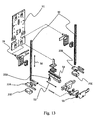
Figure 1 is a plant view of a packaging machine according to the present invention, -
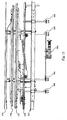
Figure 2 is a front section view of the machine offigure 1 , -
Figure 3 is a perspective view of a first feeding container according to the present invention, -
Figure 4 is a further perspective view of the container offigure 3 , -
Figure 5 - 6 are exploded views of the container offigure 3 , -
Figure 7 is a perspective view of the path of the container offigure 3 , -
Figure 8 is a perspective view of a second feeding container according to the present invention, -
Figure 9 - 13 are exploded views of the container offigure 8 , -
Figure 14 is a perspective view of the path of the container offigure 8 -
Figure 15 is a side view of the path offigure 15 , where some elements have been omitted -
Figure 16 is a detail of the path offigure 14 , where ejecting means of packages from the relative path have been emphasized -
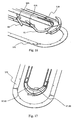
Figure 17 is a detail of the path offigure 14 . - The
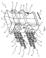
vertical packaging machine 31, forpackages 16 such as boxes, bags and similar - hereinafter named as "boxes", comprises aclosed path 32 along which gripping means 33 are moving to grasp and carry said packages, means for feeding the product to the machine and means for directing a predetermined amount of product to theboxes 16. Thepackaging machine 31 further comprises a plurality offirst feeding containers 1 of the product, closed at the bottom and disposed over the grippingmeans 33; thecontainers 1 are movable along one ormore guides 34 to follow at least part of thepath 32 of saidgripping means 33 andboxes 16 present on said gripping means. Thefirst feeding containers 1 are composed ofseveral portions portions machine 31 in order to modify at least the width of saidcontainers 1. In the shown preferred embodiment, thepackaging machine 31 is provided with a second plurality of feedingcontainers 21 to transfer the product from said first plurality ofcontainers 1 to theboxes 16, where thesecond feeding containers 21 are composed ofseveral portions portions packaging machine 31 to change the width and the thickness, that is the depth, of saidcontainers 21. - Particularly referring to
figures 1 and2 , the paths of different movable elements composing the machine are emphasized, and in particular theclosed path 32 of the grippingmeans 33 and theclosed path 34 of thefirst feeding containers 1. Among thefirst feeding containers 1 and the boxes 16 a second plurality of feedingcontainers 21 is disposed, as can be seen infigure 2 , that follows an identical path (not shown in figures) upper than thepath 32 of the grippingmeans 33, that is thecontainers 21 are always aligned over the grippingmeans 33. - The
first feeding containers 1 are carried along theclosed path 34. In the first path step thefirst feeding containers 1 receive the product from one or more counters 36. In particular the counters dose the product inside thefirst containers 1 that are closed at the bottom and then holding the product itself. More in detail, each counters 36 send the product through thefeeding lines 37 tohoppers 38, visible infigure 2 , that deliver by gravity the product inside thefirst feeding container 1 being underneath thehopper 38 at that moment. According to the present invention, thefirst feeding containers 1 are provided with means for changing at least one dimension of their own section, as better explained below, in order to better adapt to the product amount to be contained, depending on the size of theboxes 16. To hold the product until the unload thereof, thecontainers 1 have ashutter 9 that is usually closed and being opened as the product from the first containers has to be unloaded. - Preferably, as described below, the machine is provided with means known in themselves in the art, to adjust the speed of the
closed path 32 before thecurve 42 of the same path, so that to slow down thefirst feeding container 1 under thehopper 38 for the time necessary for the product delivery. Thehopper 38 can be fixed or, preferably, is provided with a travel to follow thefirst feeding containers 1 for a short length, for example of about 300 - 400 mm, necessary to deliver the product inside said feedingcontainer 1. In the embodiment shown in figures there are threecounters 36, and then three delivery stations. - The
path 34 of the machine comprises thecurve 40 at which thefirst feeding containers 1 pass over an unloadstation 39. In fact thepackaging machine 31 is provided with means for checking the correct product delivery operations, such as for example controlling the product dosing, by means of a control carried out by thesame counters 36 or other appropriate sensors. In case wherein thepackaging machine 31 detects some errors, it is able to operate on means for opening the first feeding means, in the first embodiment having the shape of ashutter 9, to operate the bottom opening of thefirst feeding container 1, according to procedures better explained hereinbelow, in order to evacuate the product into a unloadstation 39. In this way an incorrect delivery of the product to thecorresponding package 16 is avoided. The unloadstation 39 is adapted to receive and contain the product and it is preferably composed of a hopper coupled to a container placed underneath the path of thefirst feeding containers 1. - According to a preferred aspect of the present invention, the unload
station 39 is connected by areturn line 43 to a counter (counting machine) 36, in order to return into circulation immediately the product unloaded by the first containers. - After the
curve 40 thepath 34 of thefirst feeding containers 1 is aligned with the path of the second containers 21 (and of the boxes) and it takes a constant speed equal to the speed of saidsecond containers 21. Once said alignment has been achieved, thepackaging machine 31 operates on theshutter 9, or equivalent opening means, and it delivers the product from first tosecond feeding containers 21. As mentioned, thesecond feeding containers 21 are aligned with grippingmeans 33 of boxes and they follow the same path. Infig. 2 reciprocal position ofcontainers shutter 9 of thecontainer 1 is still closed, but thecontainer 21 has already moved adjacent thereto with its own product input opening. - The
second feeding containers 21 too are closed at the bottom by means whose opening can be operated by thepackaging machine 31. In the shown embodiment the means are shaped like ashutter 29, similar in shape and operation to shutter 9 of thefirst containers 1. - The machine further comprises a box feeder to gripping
means 33. In the shown embodiment, the feeder provides transferring means 35 which take flat carton boxes from a store, erect them to form an open box and arrange them on grippingmeans 33. - Usually both transferring means 35 and gripping
means 33 are known in the art. For example, in the shown embodiment the transferring means 35 are composed of a continuous vacuum manipulator, able to take up flat carton -like packages 16 from a store, not shown in figures, and to arrange them correctly in the grippingmeans 33. In the shown embodiment, the grippingmeans 33 are composed by two clamp elements adapted to receive the open box. Preferably the clamps have a variable relative distance so that to adapt to different formats ofboxes 16 the packaging machine is able to operate therewith. Other shapes of gripping 33 and transferring 35 means arc possible, depending on type of treatedpackages 16, whether they are boxes, bags or similar. - The
boxes 16 are held by grippingmeans 33, and then they follow part of thepath 32 of the same gripping means and the upper path of thesecond containers 21. In the straight length of grippingmeans 33 comprised between the transferring means 35 and thecurve 42, there are means (known in themselves) to implement the bottom closing of theboxes 16 by means of instruments known to one skilled of the art, such for example movable and/ or opposing arms with fixed parts and gluing stations. According to a preferred aspect, second feeding means 21 can be adjusted in height too, so that to come as closest as possible to the top edge of theboxes 16 when the product delivery to the latter has to happen. - In particular the product delivery from the
second container 21 to the box below 16 starts in the area just in front of thecurve 42 of the path of the grippingmeans 33. Infigure 2 the position taken by thecontainers second containers 21 from the ground changes between the path before thecurve 42, shown on the right in figure, and where the delivery starts and the path after the first curve, shown on the left. - Means for arranging the product in the boxes are provided at the
curve 42, such as for example a vibrating plane schematized with a double line and indicated with thereference numeral 42A. Following the arrow F, indicating the movement direction of containers and boxes, means for closing upper limbs of the box are disposed on the straight portion, including a gluing assembly. Anoperative station 41 is disposed along thepath 32, where boxes are separated from grippingmeans 33 and sent to subsequent stations by means of carrying elements, in the shown embodiment composed of aconveyor belt 45. - The
packaging machine 31 is provided with sensors able to control the operations onpackages 16 too. In case of processing error or absence ofpackage 16, the correspondingsecond feeding container 21 does not carry out the product delivery, the product being held and reused in a successive cycle. Additional sensors are disposed upstream thereject station 44 where defective packages or packages that did not receive the product are collected, before they arrive at thestation 41 and theconveyor belt 45. - A preferred embodiment of the
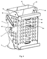
first feeding container 1, movable along thepath 34 by means ofchains 2, is shown infigures 3 - 6 . Thefirst feeding container 1 has a generically parallelepiped shape, with atop opening 3 and a bottom opening 4. Thetop opening 3, preferably always open, is shaped like a hopper to aid the product input into the container and the bottom opening is closed by ashutter 9. More in detail, thefirst feeding container 1 comprises a duct - shaped structure, formed by several portions, five portions orelements elements elements - Referring to
figure 5 , theflat element 5B is constrained to theU-shaped element 5A by known methods (riveting, welding, etc.) so that the assembly of the twoelement U-shaped element 5A and theflat element 5B. The face 5.1A is used to adjust the width of thefirst feeding container 1, as will be described hereinafter. - Remaining U-shaped 6A and flat 6B and 6C elements form a second element specular to that one described above. In detail, the
flat element 6C and the L-shapedelement 6A are coupled so that to form an element specular to theelement 5A and theflat element 6B acts as theflat element 5B. Theelement 6C is preferably made in transparent material in order to allow the product view in the container and it is constrained to theelement 6A. - The assembly of the
elements elements flat element 6B can slide along theflat element 5B and theflat element 6C can slide along the face 5.3A of theU-shaped element 5A in the same manner, whereby the first feeding container has a generically rectangular section with an adjustable dimension, along the direction indicated by thearrow 10 infigure 3 . Theelements U-shaped elements figure 5 . - The
container 1 comprises a "duct" portion formed by the portions or elements 5 and 6 and a cage 7 (fig. 6 ) in which the "duct" 5-6 is slidingly assembled. The face 7.1 of thecage 7, placed in front of the face of thecontainer 1 comprising theelements many openings chains 2 are, with which the first feeding container must be coupled, for reasons that will be explained later. - The adjusting
cage 7 is further provided with closing and opening means of the feedingcontainer 1. Such means comprises ashutter 9 hinged to the adjustingcage 7 in order to rotate when it is necessary to open the container for the product unload. In the shown embodiment theshutter 9 is hooked tosprings 11 that keep it in an usually closed position; thesprings 11 are free to extend along theguides 12 obtained in the adjustingcage 7, during the opening of the shutter. To this purpose, theshutter 9 is integral with a leverage controlling the opening and closing thereof. In a preferred embodiment shown in figures, the leverage comprises an adjustingroller 13 for example assembled by means of a bolt on aprotrusion 20 integral with the control levers of theshutter 9 that extends in front of the face of thefirst feeding container 1 opposite to thechains 2. - To open the container it is necessary to raise the
leverage 20. To this purpose the machine is provided with means, described later, to adjust the relative height of theroller 13 with respect to the adjustingcage 7. When theroller 13 is in its lower position, shown in figures, theshutter 9 closes the bottom opening 4 of thecontainer 1; when theroller 13 is raised, theshutter 9 rotates and opens the bottom opening 4 of thecontainer 1. - As afore mentioned, the
container 1 is assembled onchains 2 disposed at least on one level, with at least two chains per level and preferably at least three chains per level, in order to be conveyed along thepath 34. In the preferred arrangement, thecontainer 1 is assembled on two groups of three chain rows (fig. 3 ), each group comprising a conveyingchain 2A, placed on top, and two adjustingchains - In
figure 3 the assembly ofchains 2, 2' is shown, on which only afirst feeding container 1 is assembled for facilitating the comprehension. The container is fixed to thechain 2A with constrainingmeans 15 for coupling the chains with a first feeding container, not shown, side by side of thefirst feeding container 1 represented in figures. More in detail (fig. 3 ), the conveyingchain 2A is provided with plates that, through the respective opening 8a of the adjustingcage 7, couple rigidly with a horizontal element, not shown in figures, integral with thefirst feeding container 1. The adjustingchains 2B are provided with pins 16B adapted to be inserted into theopening 8B of the adjusting cage and to interlockingly couple with the face 5.1A of theelement 5A of thecontainer 1. - In the same way, the
pins 16C of the adjustingchain 2C, through theopening 8C of the adjustingcage 7, couple to theU-shaped element 6A of thefirst feeding container 1, seefigure 4 for reference, where pins 16C have been isolated. The width adjustment of thecontainer 1 happens by changing the reciprocal position of the portions 5 and 6 inside thecage 7, that form the "duct" part of the container; this happens by sliding thechains - Similar arrangement is present on the chains 2'.
- In
figure 7 , the view of part of the machine controlling the handling of thecontainer 1 along thepath 34 is shown. Along all walls of this machine part there is anelement 47 having guide hollows in which the chains are slidingly housed, in particular thechains head 51 containing the device of relative displacement of the adjustingchains chains 2A by means of a shaft composed of aprismatic couple 46 with a cardan joint on each end; in this way the swinging movement of such a shaft along thedirection 50 is allowed, made by the reciprocating translation motion of the whole assembly that guides, conveys and adjusts thecontainers 1. This reciprocating translation motion allows the decoupling of the moving speeds of thechains path 34 preceding thecurve 40 and the portion ofpath 34 following thecurve 40, while guaranteeing the optimal tension of saidchains path 34 preceding thecurve 40, the feed speed of thechains hoppers 38 to thefirst feeding containers 1. On the contrary, in thepath portion 34 following thecurve 40 the feed speed ofchains first feeding containers 1 equal to the speed of thesecond feeding containers 21. - Also the
second container 21 in the shown embodiment (figures 9-13 ) comprises a "duct" structure formed by portions that slide one with respect to the other, assembled in acage 27, in its turn assembled on conveying chains along thepath 32. The "duct" comprises twoU-shaped portions portions - Considering at first only the two
elements second feeding container 21 shaped like a C with adjustable depth (or thickness). In particular, theportion 17B is provided withpins 19 that engage along theopenings 22 obtained on sides of theportion 17A. Moreover, thepins 19 are adapted to insert intoguides 23 obtained on thecage 27. In this way the twoportions cage 27. Similar matter goes for theportions portions - As happens for the
first container 1 too, the two C-shaped semi-portions, whose the first is formed by theportions portions portion 18A can slide with respect toportion 17A and theportion 18B can slide with respect to theportion 17B to change the "duct" width in which the product is housed and to adjust dimensions and shape of unload opening of thecontainer 21 according to the input opening of the box below. As a result, the section of the second feeding container, having generically rectangular shape, can be adjusted in both dimensions, as shown byarrows figure 8 . - In
figure 10 , coupling between thecage 27 of thecontainer 21 and theshutter 29 is shown, similar to what happens for thecage 7 and theshutter 9 in the first container, whereby reference is made to the above description. For safety of comprehension, similar elements have been associated with similar reference numerals. - In their turn, coupled portions 17 and 18 have been slidingly assembled on a
base plate 51. Theplate 51 is assembled fixed on conveying chains and it is assembled on thecage 27 with rails that allow the cage to slide vertically on the plate. In particular, in shown figure the carryingplate 51 is made integral with two conveying chains (not shown) in the connection points 52. Particularly referring tofigures 11 - 13 , adjusting means 25A - 25D of thesecond feeding container 21 are now described. - In
figure 11 the adjustingrollers roller 25A is made integral, in known ways, by means of screws, bolts or similar, to the adjustingcage 27 of thesecond feeding container 21. Thepackaging machine 31, as described later, can handle vertically an adjustingroller 25A. By changing the height of the adjustingroller 25A, heights of thesecond adjusting cage 27 and thesecond feeding container 21 change. In particular, the adjustingcage 27 is forced to slide vertically along therails 24 made integral with the carryingplate 51. The descent of thesecond feeding container 21 towards thepackage 16 happens through the adjustingroller 25A. - The
roller 25B is constrained to the carryingplate 51. Thepackaging machine 31 is further provided with means, as described later, adapted to handle vertically said roller 25B. Said handling of the height of theroller 25B acts on the depth of thesecond feeding container 21 through kinematic mechanisms (shown in schematic manner), or rather it allows the sliding ofelements elements guide arrow 62 infigure 8 . The depth of thesecond feeding container 21 is then adjusted through the adjustingroller 25B based on the depth of thepackage 16. - In
figure 12 the adjustingrollers 25C are shown, preferably in pairs. The pairs of adjustingrollers 25C is movable in height under the action of thepackaging machine 31, better described later. Because the operation of the two adjustingrollers 25C is specular, for easiness of discussion only one adjustingroller 25C is described. Said adjustingroller 25C is integral with alever 26 that has a fulcrum on the carryingplate 51. The arm of theleverage 26, opposite to the arm where the adjustingroller 25C is, handles an activatingelement 28 acting on theportion 17A of thesecond feeding container 21, causing the removal or approach thereof with respect to theportion 18A of thesecond feeding container 21, as a function of the rotation way of thelever 26. The width of thesecond feeding container 21 is then adjusted through the adjustingroller 25C based on the width of thepackage 16. - In
figure 13 the adjustingroller 25D and the adjustingelements 25E are shown. - The adjusting
roller 25D has a substantially vertical axis, contrary to the adjustingrollers 25Apackaging machine 31 to displace the adjustingroller 25D horizontally. More in detail, the adjustingroller 25D is integral with arail 54, being able to slide perpendicularly with respect to the carryingplate 51, in the direction shown by thearrow 53. Through the adjustingroller 25D the adjustment of the back rest happens, based on the depth of thebox format 16. In addition, the back rest tray acts also as an ejector thereby allowing the box to be pushed towards theoperative station 41 or thereject station 44. This tray, in order to operate correctly, provides for a rest affecting a great surface that changes with the format of the box 18 and placed on the box wall facing towards the inside of the carousel. Because of the great height variability of boxes 18, in the shown embodiment a swinging rest tray is selected, driven by a mechanical lever that takes motion from theelement 25E, the latter moving vertically during height adjustment of the box format. In this way, as the box height increases, thetray 55 increases its tilt with respect to the horizontal lie it takes for the minimum format, thereby increasing with this movement the vertical extension of the rest surface of the box. - The adjusting
elements 25E are C-shaped and they are inserted into appropriate means of thepackaging machine 31, better defined later, able to handle them vertically. In particular, the adjusting means 25 are integral withrails 30 that could slide in parallel, according to the direction indicated by thearrow 56, with the activatingelement 28 and the carryingplate 51. The height adjustment of thepackage 16 happens through the adjustingelement 25E, so that to be able to position thesecond feeding container 21 just over the opening of theboxes 16, in order to optimize the product transfer thereon. - In the shown embodiment, in their turn the gripping
means 33, that is the twoclamp elements 33A and 33B, are fixed to rails 30. Therails 30 are arranged to be integral with the width changes of thesecond container 21. In other words, when the L-shapedportion 17B of thesecond feeding container 21 is subjected to displacement with respect to the L-shapedportion 18B, through the activatingelements 28 driven by the previously described adjustingroller 25B, the same displacement is transferred in sequence torails 30 and to clampelements 33A and 33B of the grippingmeans 33. - In
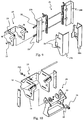
figures 14 - 16 thepath 32 of thegripping elements 33 and the second feeding container is shown, with particular attention for the handling means ofmeans 25A - 25E adapted to change the dimension of thesecond feeding container 21. - In particular, the
packaging machine 31 has a fixedguide 57A, shaped like a C, defining a path for the adjustingroller 57A. In particular it is noted that, at thecurve 42, the fixedguide 57A has a slope 57.1A coinciding with the approach of thesecond feeding container 21 towards thebox 16 and the product unload therein. - As the fixed
guide 57A is not movable, the path of the adjustingroller 25A is always the same in every operative cycle of thepackaging machine 31. - Below the fixed
guide 57A, the packaging machine has theguides rollers guides 57B screw. Whereas a further motor assembly 59.2A handles a group of warms 58.2A on which theguide 57C screws. - Below the
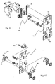
guide 57C, the packaging machine has theguide 57D, vertically movable and shaped like a U, adapted to handle the adjustingroller 25D. - At the
curve 42, theguide 57D is formed by two connecting flexible elements 57.1D and 57.2D or, as shown in figures, conveniently shaped so that to slide one with respect to the other, adapted to guarantee the path continuity of the adjustingroller 57D for all possible dimensions of theguide 57D. Theguide 57D is provided with ejecting means 60 and 61 (figure 16 ) of theboxes 16 from thepath 34. The ejecting means 60 and 61 are shaped to intercept the path of the adjustingroller 57D, so that to handle the ejectingtray 55 towards thebox 16 and to release thesame box 16 from the grippingmeans 33. In the embodiment shown in figures the ejecting means 60 and 61 are shaped like a lever, movable around thefulcra path 32. Appropriate means, not shown, are adapted to handle the ejecting means 60 and 61, that is their rotation around thefulcra path 32 of the adjustingrollers 25D or to avoid the passage thereof. In particular, the activation of the ejecting means 60 pushes thebox 16 towards thereject station 44 whereas the activation of the ejecting means 61 pushes thebox 16 towards theoperative station 41. - Below the
guide 57D there is theslide flange 57E, adapted to handle theadjusting elements 25E. In particular the adjustingelements 25E have an opening with a shape complementary to the profile of theslide flange 57E and it fits interlockingly on the latter. Thepackaging machine 31 has means adapted to handle vertically theslide flange 57E. In the embodiment shown in figures, said means are composed of themotor assembly 59B and are adapted to activate the group of warms 58B. Theslide flange 57E acts also as slide plane that supports theboxes 16 at the bottom. Then by handling vertically theslide flange 57E, it is possible to adjust the relative position of the bottom of thebox 16 as the height of the box format changes, so that to maintain constant the elevation of the top opening of the box with respect to the height of thesecond feeding containers 21, that is adjusted by the path defined by the fixedguide 57A. - Electrical or pneumatic drives, not shown in figures, are used to handle the
rollers 13 and to drive consequently the opening of theshutters feeding containers - To the method embodiment herein represented by way of example only, various modifications may be made without therefore falling out from the scope of the present invention.
Claims (14)
- Vertical packaging machine (31) for packages (16) such as boxes, bags and the like, comprising a closed path (32) along which gripping means (33, 33A, 33B) are movable to grasp and carry said packages (16), means (36, 37) for feeding products to the machine and dosing means (38) to direct a predetermined amount of product to said packages, characterized by further comprising at least one plurality of product feeding containers (1, 21), said containers (1, 21) being disposed above a corresponding plurality of gripping means (33) of the packages (16) and being movable along one or more guides to follow at least part of the path of said gripping means (33) and packages (16) present on said gripping means (33); where said containers (1, 21) are assembled on means sliding inside said guides and they are composed of several portions (5A, 5B, 6A, 6B, 6C, 17A, 17B, 18A, 18B) and the position of said portions (5A, 5B, 6A, 6B, 6C, 17A, 17B, 18A, 18B) can be adjusted by said machine (31) to change the dimensions of said containers (1, 21).
- Packaging machine according to claim 1, wherein there is a plurality of first containers (1) to receive the product from the dosing means (38) and a plurality of second containers (21) to transfer the product from said first containers (1) to said packages (16), the second containers (21) are composed of several portions (17A, 17B, 18A, 18B) and the position of said portions can be adjusted by said machine (31) to change the width and the thickness of said containers (21).
- Packaging machine according to one of the preceding claims, wherein said first and second containers (1, 21) comprise kinematic mechanisms to adjust the reciprocal position of the afore said portions (5A, 5B, 6A, 6B, 6C, 17A, 17B, 18A, 18B) of the product feeding containers, wherein said kinematic mechanisms are operated by said machine (31) to change the dimensions of said containers.
- Packaging machine (31) according to claim 2, wherein said first containers (1) are assembled on chains (2, 2') sliding along fixed guides, at least two (2B, 2C) of said chains (2, 2') being movable in opposite directions to operate said kinematic mechanisms to change the container dimensions.
- Packaging machine (31) according to one of the claims 2 to 4, wherein said machine further comprises: one or more fixed guides (57A) in which chains for carrying said second containers are sliding; one or more movable guides (57B - 57E) to accommodate the ends of said kinematic mechanisms (25A - 25E) to change the dimensions of the second containers (21); and means (58, 59) to adjust the position of at least some of said guides (57B - 57E) with respect to the rest of the packaging machine (31) and operate said kinematic mechanisms (25A - 25E) consequently.
- Packaging machine (31) according to claim 5, wherein said second containers (21) comprise a base (51) on which the afore said gripping means of the packages are assembled.
- Packaging machine according to claim 5 or 6, wherein said second containers (21) comprise at least two end elements of the kinematic mechanisms (25A - 25E) which are accommodated in two corresponding movable guides.
- Packaging machine (31) according to one of the preceding claims, wherein said first containers (1) follow a path different from the path of said second containers (21) and where the path of said second containers (21) coincide with the path of said carrying and gripping means (33, 33A, 33B) of packages (16).
- Packaging machine (31) according to one of the preceding claims, further comprising means to control the opening of the lower container portion, said means comprising a movable wall (9, 29) for closing the container; a lever (20) assembled on the container to operate said wall; means assembled on the machine to operate said lever.
- Product feeding container (1, 21) for a vertical packaging machine (31) for packages (16) such as boxes, bags and the like, the machine comprising a closed path (32) along which gripping means (33, 33A, 33B) are movable to grasp and carry said packages (16), means (36, 37) for feeding products to the machine and dosing means (38) to direct a predetermined amount of product to said packages, characterized by comprising a duct-shaped structure formed by a plurality of portions (5A, 5B, 6A, 6B, 6C, 17A, 17B, 18A, 18B) reciprocally movable to change the dimensions of the feeding container itself, the feeding container (1, 21) further comprising a cage (7, 27) in which the duct-shaped structure is slidingly assembled, wherein the changed dimensions of the container are selected from at least the width of the container (1), and the width and the thickness of the container (21).
- Method for packaging a product into packages (16) with a machine according to one of the claims 1 to 9, characterized by using at least one plurality of containers (1, 21) to receive the product from product dosing means, holding temporarily the product in said containers (1, 21) and transferring the dosed product from said containers into said packages (1, 16), and by changing the position of a part of said machine to operate kinematic mechanisms for adjusting the dimensions of the output openings of said product feeding containers to adapt them to those of the input openings of the packages (16) treated in said machine, when it is necessary.
- Method according to claim 11, comprising the following steps: the product dosed by said dosing means is fed to a plurality of first containers (1); the dosed product is transferred by the first containers (1) to a plurality of second containers (21) having an output opening with dimensions and shape substantially corresponding to dimensions and shape of the input opening of packages (16); the product is transferred by said second containers to said packages (16).
- Method according to claim 12, wherein dimensions and shape of said second containers (21) are adjusted acting on width and depth of said containers (21).
- Method according to one of the claims 11 to 13, wherein the product amount accuracy in the first containers (1) is checked before transferring said product into said second containers (21).
Applications Claiming Priority (2)
| Application Number | Priority Date | Filing Date | Title |
|---|---|---|---|
| IT002359A ITMI20112359A1 (en) | 2011-12-22 | 2011-12-22 | VERTICAL MACHINE FOR PACKAGING WITH QUICK FORMAT CHANGE AND OPERATING PROCEDURE |
| PCT/IB2012/002959 WO2013093622A1 (en) | 2011-12-22 | 2012-12-20 | Vertical packaging machine and method |
Publications (2)
| Publication Number | Publication Date |
|---|---|
| EP2794404A1 EP2794404A1 (en) | 2014-10-29 |
| EP2794404B1 true EP2794404B1 (en) | 2016-06-29 |
Family
ID=45614932
Family Applications (1)
| Application Number | Title | Priority Date | Filing Date |
|---|---|---|---|
| EP12824707.9A Active EP2794404B1 (en) | 2011-12-22 | 2012-12-20 | Vertical packaging machine and method |
Country Status (7)
| Country | Link |
|---|---|
| US (1) | US20140360136A1 (en) |
| EP (1) | EP2794404B1 (en) |
| BR (1) | BR112014015379A2 (en) |
| ES (1) | ES2595429T3 (en) |
| IT (1) | ITMI20112359A1 (en) |
| PL (1) | PL2794404T3 (en) |
| WO (1) | WO2013093622A1 (en) |
Families Citing this family (3)
| Publication number | Priority date | Publication date | Assignee | Title |
|---|---|---|---|---|
| DE102014210234A1 (en) * | 2013-06-24 | 2014-12-24 | Robert Bosch Gmbh | Device for producing bag packages |
| MX2017014372A (en) * | 2015-05-29 | 2018-03-02 | Graphic Packaging Int Llc | Packaging system. |
| CN114642897B (en) * | 2020-12-21 | 2023-06-09 | 常州大连理工大学智能装备研究院 | Extraction system and process of high-purity ginseng extract |
Family Cites Families (9)
| Publication number | Priority date | Publication date | Assignee | Title |
|---|---|---|---|---|
| US3381446A (en) * | 1966-03-09 | 1968-05-07 | Roto American Corp | Packaging machine for opening and filling pouch-type bags |
| US3782878A (en) * | 1972-03-14 | 1974-01-01 | Campbell Soup Co | Rotary extruder and loader |
| CA1306224C (en) * | 1989-05-08 | 1992-08-11 | Hugo Johnsen | Baler with adjustable chute |
| US5544738A (en) * | 1994-11-07 | 1996-08-13 | The Paxall Group | Adjustable pocket mechanism |
| US6050061A (en) | 1998-11-03 | 2000-04-18 | Klockner Bartelt, Inc. | Pouch carrying apparatus |
| US6814210B1 (en) * | 2003-04-16 | 2004-11-09 | Lockheed Martin Corporation | Self-storing material sortation deflector system |
| WO2009027946A1 (en) * | 2007-08-31 | 2009-03-05 | H.G. Molenaar & Co. (Pty) Ltd | Filling arrangement |
| JP5247156B2 (en) * | 2008-01-08 | 2013-07-24 | 東洋自動機株式会社 | Bag packing machine |
| EP2256043A1 (en) * | 2009-05-28 | 2010-12-01 | Seelen A/S | Four-piece spout assembly |
-
2011
- 2011-12-22 IT IT002359A patent/ITMI20112359A1/en unknown
-
2012
- 2012-12-20 BR BR112014015379A patent/BR112014015379A2/en not_active Application Discontinuation
- 2012-12-20 EP EP12824707.9A patent/EP2794404B1/en active Active
- 2012-12-20 WO PCT/IB2012/002959 patent/WO2013093622A1/en active Application Filing
- 2012-12-20 PL PL12824707T patent/PL2794404T3/en unknown
- 2012-12-20 US US14/367,603 patent/US20140360136A1/en not_active Abandoned
- 2012-12-20 ES ES12824707.9T patent/ES2595429T3/en active Active
Also Published As
| Publication number | Publication date |
|---|---|
| BR112014015379A2 (en) | 2017-08-22 |
| US20140360136A1 (en) | 2014-12-11 |
| ITMI20112359A1 (en) | 2013-06-23 |
| EP2794404A1 (en) | 2014-10-29 |
| WO2013093622A1 (en) | 2013-06-27 |
| ES2595429T3 (en) | 2016-12-30 |
| PL2794404T3 (en) | 2017-01-31 |
Similar Documents
| Publication | Publication Date | Title |
|---|---|---|
| US5170610A (en) | Means for and methods of loading irregularly shaped objects into automatic packaging machines | |
| EP1371564B1 (en) | Method and machine for packing a product using a flat tubular package | |
| JP4823356B2 (en) | Packaging system with loaded rotary conveyor | |
| JP3837436B2 (en) | Multi-pack packaging equipment | |
| RU2334668C2 (en) | Method and device for producing vessels packages | |
| DK171077B1 (en) | Machine for packing objects | |
| US3225510A (en) | Article cartoning machine | |
| US9346580B2 (en) | Carton decasing system | |
| KR101501768B1 (en) | Wrap around caser continuously bundling the numerous bottles | |
| US8943783B2 (en) | System and method for handling wicket bags | |
| CN103391881A (en) | Device and method for packaging articles | |
| CN210338406U (en) | Full-automatic case packer | |
| US10919657B2 (en) | Method of, and apparatus for, feeding products into containers | |
| EP2794404B1 (en) | Vertical packaging machine and method | |
| EP4003845B1 (en) | An article picking and treating apparatus | |
| US9834402B2 (en) | Method and device for handling sanitary articles | |
| US11117749B2 (en) | Apparatus for handling articles as well as method for exchanging at least one transport module and at least one work module of the apparatus | |
| JP3628086B2 (en) | Method for transporting snack confectionery packaging bag and method for transporting and packing snack confectionery packaging bag | |
| US3881298A (en) | Cartoning apparatus | |
| EP1410995B1 (en) | A machine for packing cartons containing bottles separated by separators | |
| CA1141646A (en) | Packaging machine | |
| CN108298133B (en) | Method for transferring blister packs | |
| US5267426A (en) | Product loading system | |
| KR101603419B1 (en) | Three-sided wrapped food accumulator | |
| CN112752722B (en) | Apparatus and method for conveying products |
Legal Events
| Date | Code | Title | Description |
|---|---|---|---|
| PUAI | Public reference made under article 153(3) epc to a published international application that has entered the european phase |
Free format text: ORIGINAL CODE: 0009012 |
|
| 17P | Request for examination filed |
Effective date: 20140718 |
|
| AK | Designated contracting states |
Kind code of ref document: A1 Designated state(s): AL AT BE BG CH CY CZ DE DK EE ES FI FR GB GR HR HU IE IS IT LI LT LU LV MC MK MT NL NO PL PT RO RS SE SI SK SM TR |
|
| DAX | Request for extension of the european patent (deleted) | ||
| 17Q | First examination report despatched |
Effective date: 20150722 |
|
| GRAP | Despatch of communication of intention to grant a patent |
Free format text: ORIGINAL CODE: EPIDOSNIGR1 |
|
| INTG | Intention to grant announced |
Effective date: 20160118 |
|
| GRAS | Grant fee paid |
Free format text: ORIGINAL CODE: EPIDOSNIGR3 |
|
| GRAA | (expected) grant |
Free format text: ORIGINAL CODE: 0009210 |
|
| AK | Designated contracting states |
Kind code of ref document: B1 Designated state(s): AL AT BE BG CH CY CZ DE DK EE ES FI FR GB GR HR HU IE IS IT LI LT LU LV MC MK MT NL NO PL PT RO RS SE SI SK SM TR |
|
| REG | Reference to a national code |
Ref country code: GB Ref legal event code: FG4D |
|
| REG | Reference to a national code |
Ref country code: CH Ref legal event code: EP |
|
| REG | Reference to a national code |
Ref country code: AT Ref legal event code: REF Ref document number: 808886 Country of ref document: AT Kind code of ref document: T Effective date: 20160715 |
|
| REG | Reference to a national code |
Ref country code: IE Ref legal event code: FG4D |
|
| REG | Reference to a national code |
Ref country code: DE Ref legal event code: R096 Ref document number: 602012020080 Country of ref document: DE |
|
| REG | Reference to a national code |
Ref country code: NL Ref legal event code: FP |
|
| REG | Reference to a national code |
Ref country code: SE Ref legal event code: TRGR |
|
| REG | Reference to a national code |
Ref country code: LT Ref legal event code: MG4D |
|
| PG25 | Lapsed in a contracting state [announced via postgrant information from national office to epo] |
Ref country code: NO Free format text: LAPSE BECAUSE OF FAILURE TO SUBMIT A TRANSLATION OF THE DESCRIPTION OR TO PAY THE FEE WITHIN THE PRESCRIBED TIME-LIMIT Effective date: 20160929 Ref country code: FI Free format text: LAPSE BECAUSE OF FAILURE TO SUBMIT A TRANSLATION OF THE DESCRIPTION OR TO PAY THE FEE WITHIN THE PRESCRIBED TIME-LIMIT Effective date: 20160629 Ref country code: LT Free format text: LAPSE BECAUSE OF FAILURE TO SUBMIT A TRANSLATION OF THE DESCRIPTION OR TO PAY THE FEE WITHIN THE PRESCRIBED TIME-LIMIT Effective date: 20160629 |
|
| PG25 | Lapsed in a contracting state [announced via postgrant information from national office to epo] |
Ref country code: GR Free format text: LAPSE BECAUSE OF FAILURE TO SUBMIT A TRANSLATION OF THE DESCRIPTION OR TO PAY THE FEE WITHIN THE PRESCRIBED TIME-LIMIT Effective date: 20160930 Ref country code: LV Free format text: LAPSE BECAUSE OF FAILURE TO SUBMIT A TRANSLATION OF THE DESCRIPTION OR TO PAY THE FEE WITHIN THE PRESCRIBED TIME-LIMIT Effective date: 20160629 Ref country code: RS Free format text: LAPSE BECAUSE OF FAILURE TO SUBMIT A TRANSLATION OF THE DESCRIPTION OR TO PAY THE FEE WITHIN THE PRESCRIBED TIME-LIMIT Effective date: 20160629 Ref country code: HR Free format text: LAPSE BECAUSE OF FAILURE TO SUBMIT A TRANSLATION OF THE DESCRIPTION OR TO PAY THE FEE WITHIN THE PRESCRIBED TIME-LIMIT Effective date: 20160629 |
|
| REG | Reference to a national code |
Ref country code: AT Ref legal event code: MK05 Ref document number: 808886 Country of ref document: AT Kind code of ref document: T Effective date: 20160629 |
|
| REG | Reference to a national code |
Ref country code: FR Ref legal event code: PLFP Year of fee payment: 5 |
|
| REG | Reference to a national code |
Ref country code: ES Ref legal event code: FG2A Ref document number: 2595429 Country of ref document: ES Kind code of ref document: T3 Effective date: 20161230 |
|
| PG25 | Lapsed in a contracting state [announced via postgrant information from national office to epo] |
Ref country code: EE Free format text: LAPSE BECAUSE OF FAILURE TO SUBMIT A TRANSLATION OF THE DESCRIPTION OR TO PAY THE FEE WITHIN THE PRESCRIBED TIME-LIMIT Effective date: 20160629 Ref country code: RO Free format text: LAPSE BECAUSE OF FAILURE TO SUBMIT A TRANSLATION OF THE DESCRIPTION OR TO PAY THE FEE WITHIN THE PRESCRIBED TIME-LIMIT Effective date: 20160629 Ref country code: CZ Free format text: LAPSE BECAUSE OF FAILURE TO SUBMIT A TRANSLATION OF THE DESCRIPTION OR TO PAY THE FEE WITHIN THE PRESCRIBED TIME-LIMIT Effective date: 20160629 Ref country code: IS Free format text: LAPSE BECAUSE OF FAILURE TO SUBMIT A TRANSLATION OF THE DESCRIPTION OR TO PAY THE FEE WITHIN THE PRESCRIBED TIME-LIMIT Effective date: 20161029 Ref country code: SK Free format text: LAPSE BECAUSE OF FAILURE TO SUBMIT A TRANSLATION OF THE DESCRIPTION OR TO PAY THE FEE WITHIN THE PRESCRIBED TIME-LIMIT Effective date: 20160629 |
|
| PG25 | Lapsed in a contracting state [announced via postgrant information from national office to epo] |
Ref country code: PT Free format text: LAPSE BECAUSE OF FAILURE TO SUBMIT A TRANSLATION OF THE DESCRIPTION OR TO PAY THE FEE WITHIN THE PRESCRIBED TIME-LIMIT Effective date: 20161031 Ref country code: BE Free format text: LAPSE BECAUSE OF FAILURE TO SUBMIT A TRANSLATION OF THE DESCRIPTION OR TO PAY THE FEE WITHIN THE PRESCRIBED TIME-LIMIT Effective date: 20160629 Ref country code: AT Free format text: LAPSE BECAUSE OF FAILURE TO SUBMIT A TRANSLATION OF THE DESCRIPTION OR TO PAY THE FEE WITHIN THE PRESCRIBED TIME-LIMIT Effective date: 20160629 Ref country code: SM Free format text: LAPSE BECAUSE OF FAILURE TO SUBMIT A TRANSLATION OF THE DESCRIPTION OR TO PAY THE FEE WITHIN THE PRESCRIBED TIME-LIMIT Effective date: 20160629 |
|
| REG | Reference to a national code |
Ref country code: DE Ref legal event code: R097 Ref document number: 602012020080 Country of ref document: DE |
|
| PLBE | No opposition filed within time limit |
Free format text: ORIGINAL CODE: 0009261 |
|
| STAA | Information on the status of an ep patent application or granted ep patent |
Free format text: STATUS: NO OPPOSITION FILED WITHIN TIME LIMIT |
|
| PG25 | Lapsed in a contracting state [announced via postgrant information from national office to epo] |
Ref country code: DK Free format text: LAPSE BECAUSE OF FAILURE TO SUBMIT A TRANSLATION OF THE DESCRIPTION OR TO PAY THE FEE WITHIN THE PRESCRIBED TIME-LIMIT Effective date: 20160629 |
|
| 26N | No opposition filed |
Effective date: 20170330 |
|
| STAA | Information on the status of an ep patent application or granted ep patent |
Free format text: STATUS: NO OPPOSITION FILED WITHIN TIME LIMIT |
|
| REG | Reference to a national code |
Ref country code: CH Ref legal event code: PL |
|
| PG25 | Lapsed in a contracting state [announced via postgrant information from national office to epo] |
Ref country code: BG Free format text: LAPSE BECAUSE OF FAILURE TO SUBMIT A TRANSLATION OF THE DESCRIPTION OR TO PAY THE FEE WITHIN THE PRESCRIBED TIME-LIMIT Effective date: 20160929 Ref country code: SI Free format text: LAPSE BECAUSE OF FAILURE TO SUBMIT A TRANSLATION OF THE DESCRIPTION OR TO PAY THE FEE WITHIN THE PRESCRIBED TIME-LIMIT Effective date: 20160629 |
|
| PG25 | Lapsed in a contracting state [announced via postgrant information from national office to epo] |
Ref country code: MC Free format text: LAPSE BECAUSE OF FAILURE TO SUBMIT A TRANSLATION OF THE DESCRIPTION OR TO PAY THE FEE WITHIN THE PRESCRIBED TIME-LIMIT Effective date: 20160629 |
|
| REG | Reference to a national code |
Ref country code: IE Ref legal event code: MM4A |
|
| PG25 | Lapsed in a contracting state [announced via postgrant information from national office to epo] |
Ref country code: LI Free format text: LAPSE BECAUSE OF NON-PAYMENT OF DUE FEES Effective date: 20161231 Ref country code: LU Free format text: LAPSE BECAUSE OF NON-PAYMENT OF DUE FEES Effective date: 20161220 Ref country code: CH Free format text: LAPSE BECAUSE OF NON-PAYMENT OF DUE FEES Effective date: 20161231 |
|
| PG25 | Lapsed in a contracting state [announced via postgrant information from national office to epo] |
Ref country code: IE Free format text: LAPSE BECAUSE OF NON-PAYMENT OF DUE FEES Effective date: 20161220 |
|
| REG | Reference to a national code |
Ref country code: FR Ref legal event code: PLFP Year of fee payment: 6 |
|
| PG25 | Lapsed in a contracting state [announced via postgrant information from national office to epo] |
Ref country code: HU Free format text: LAPSE BECAUSE OF FAILURE TO SUBMIT A TRANSLATION OF THE DESCRIPTION OR TO PAY THE FEE WITHIN THE PRESCRIBED TIME-LIMIT; INVALID AB INITIO Effective date: 20121220 |
|
| PG25 | Lapsed in a contracting state [announced via postgrant information from national office to epo] |
Ref country code: CY Free format text: LAPSE BECAUSE OF FAILURE TO SUBMIT A TRANSLATION OF THE DESCRIPTION OR TO PAY THE FEE WITHIN THE PRESCRIBED TIME-LIMIT Effective date: 20160629 Ref country code: MK Free format text: LAPSE BECAUSE OF FAILURE TO SUBMIT A TRANSLATION OF THE DESCRIPTION OR TO PAY THE FEE WITHIN THE PRESCRIBED TIME-LIMIT Effective date: 20160629 |
|
| PG25 | Lapsed in a contracting state [announced via postgrant information from national office to epo] |
Ref country code: MT Free format text: LAPSE BECAUSE OF NON-PAYMENT OF DUE FEES Effective date: 20161220 |
|
| PG25 | Lapsed in a contracting state [announced via postgrant information from national office to epo] |
Ref country code: AL Free format text: LAPSE BECAUSE OF FAILURE TO SUBMIT A TRANSLATION OF THE DESCRIPTION OR TO PAY THE FEE WITHIN THE PRESCRIBED TIME-LIMIT Effective date: 20160629 |
|
| PGFP | Annual fee paid to national office [announced via postgrant information from national office to epo] |
Ref country code: IE Payment date: 20181220 Year of fee payment: 7 |
|
| PGFP | Annual fee paid to national office [announced via postgrant information from national office to epo] |
Ref country code: ES Payment date: 20200114 Year of fee payment: 8 |
|
| REG | Reference to a national code |
Ref country code: ES Ref legal event code: FD2A Effective date: 20220412 |
|
| PG25 | Lapsed in a contracting state [announced via postgrant information from national office to epo] |
Ref country code: ES Free format text: LAPSE BECAUSE OF NON-PAYMENT OF DUE FEES Effective date: 20201221 |
|
| PG25 | Lapsed in a contracting state [announced via postgrant information from national office to epo] |
Ref country code: PL Free format text: LAPSE BECAUSE OF NON-PAYMENT OF DUE FEES Effective date: 20191220 |
|
| PGFP | Annual fee paid to national office [announced via postgrant information from national office to epo] |
Ref country code: TR Payment date: 20221026 Year of fee payment: 11 Ref country code: SE Payment date: 20221026 Year of fee payment: 11 Ref country code: GB Payment date: 20221215 Year of fee payment: 11 |
|
| PGFP | Annual fee paid to national office [announced via postgrant information from national office to epo] |
Ref country code: NL Payment date: 20231025 Year of fee payment: 12 |
|
| PGFP | Annual fee paid to national office [announced via postgrant information from national office to epo] |
Ref country code: IT Payment date: 20231204 Year of fee payment: 12 Ref country code: FR Payment date: 20231120 Year of fee payment: 12 Ref country code: DE Payment date: 20231023 Year of fee payment: 12 |